

10. Avoid using front and rear washing functions excessively or for long periods of time as
such overuse may increase the possibility of washing away desirable resident bacteria and
causing an imbalance of bacteria in your body. If you are pregnant, are being treated for a
gynecological condition, develop excessive irritation in the area of use, or if you have
questions, please speak to your doctor before beginning or continuing use of the product.

2. Product description
This product provides features to enhance personal toilet hygiene and comfort. This product features
include a posterior wash, a bidet, a warm air dryer, and a seat heater, as well as controls for these
functions.
This product consists of a body (with heated toilet seat, toilet seat lid, warm water tank, and power cord),
hardware to mount the body on a toilet and connect it to the toilet water supply and this installation and
use manual.
This product is equipped with the following features:
posterior wash with water flow strength controls
•
bidet with water flow strength controls
•
warm air dryer with air temperature controls
•
seat heater with heat level control
•
wash and bidet water temperature control
•
seat and water temperature indicators
•
wash and bidet nozzle self-cleaning
•
stop button for the wash, bidet, and dryer
•
Note:
When carrying the product, take care not to inadvertently bump or drop it.
•
This product has been already inspected using tap water. A small amount of water may be
•
detected when installing the unit; this should not be a cause for concern.
5
3. Installing this product
Installation requirements
Before installing this product, ensure that each of the following installation requirements is met.
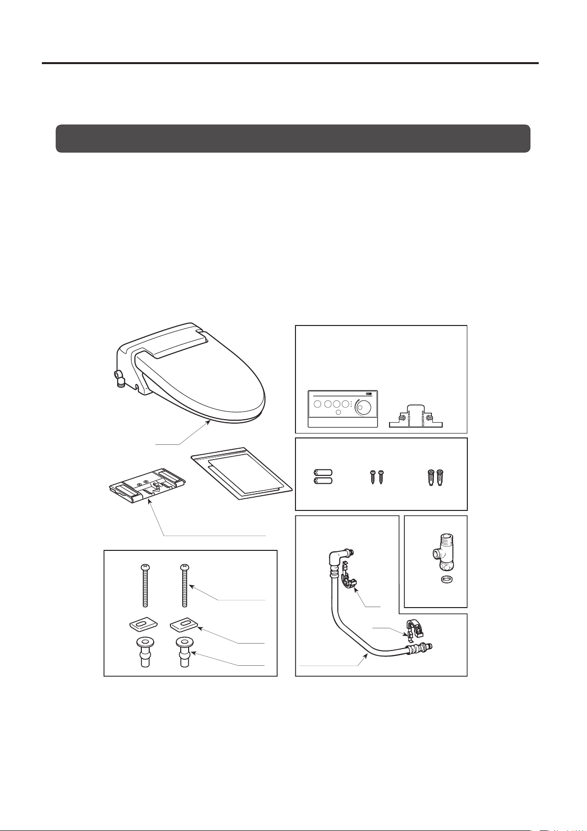
Product carton contents
Remove the parts from the product carton and make sure all the parts in the parts list (below) are
present. Inspect the parts carefully to make sure they are in good condition.
If any part is damaged or missing, do not install this product. Contact the nearest sales outlet for the
part(s) you need.
This product carton should contain the following parts:
Body (with heated toilet seat, toilet seat lid and power cord)
•
Slide plate
•
Manual set
•
Mounting bolts, washers, and bushings (2 pieces each)
•
Junction fitting (with a packing)
•
Body water supply hose (with 2 clips)
•
*Remote control unit and bracket are
packed in the box of the parts.
Body
Manual set
Slide plate
(This plate attaches to the body.)
Mounting bolt
Washer
Bushing
Remote control unit
Bracket
For remote control unit
Batteries (2) Wood screw Plastic anchor
Junction fitting
Clip
Clip
Water supply hose
(95 cm long)
Packing
(2 mm) thick
6
Ground fault circuit interrupter
A ground fault circuit interrupter must be installed in the circuit that supplies power to this product.
Power supply
This product is for use on a nominal 220 V circuit. Use a 220 V, 50 Hz power supply. The maximum
power consumption is 305 W. Electrical wiring must be installed that meets these conditions. The plug
outlet shall be placed in accessible location after installation.
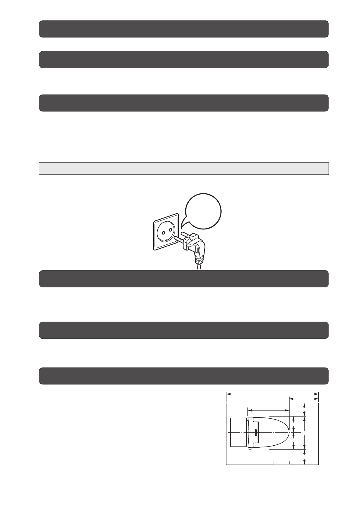
Grounding
This product must be grounded. In the event of an electrical short circuit, grounding reduces the risk
of electric hazard by providing an escape wire for the electric current. The power cord has a grounding
wire and a three-blade grounding plug (shown below). Do not use an adapter with the product's power
plug, or use any other method to connect the plug to an improperly configured outlet.
The outlet to which the product is connected must be 220 V, 50 Hz, with a minimum electrical rating of 3
A. The outlet must be properly installed and grounded, and have a three-slot outlet (shown below).
DANGER:Improper use of the grounding plug can result in a risk of electric hazard.
If it is necessary to use an extension cord, use only a three wire extension cord that has a three-blade
grounding plug. The extension cord must be rated for at least 220 V, 50 Hz, 3 A.
220V
Installation location
This product is manufactured for family or personal use. In order to avoid damage to the electronic
components, prevent the body of this product from getting wet by drops or splashes of water. In
extremely humid conditions, please provide adequate ventilation by operating an exhaust fan or opening
a window (or door).
Water supply
Use only the tap water line to supply water to this product. There is danger of ground water or other
water that is not tap water causing trouble with this product.
The tap water pressure must be 0.06 to 0.74 MPa (0.6 to 7.5 kgf/cm
2
).
Checking the toilet room
The dimensions required for mounting this product on a
toilet are as shown in the figure below. Check to make
sure there is sufficient space inside the toilet room and
that there are no obstructions in the way.
120 or more
55.8
40 or more
3 or more
20.7
42.6
21.9
3 or more
Unit : cm
7
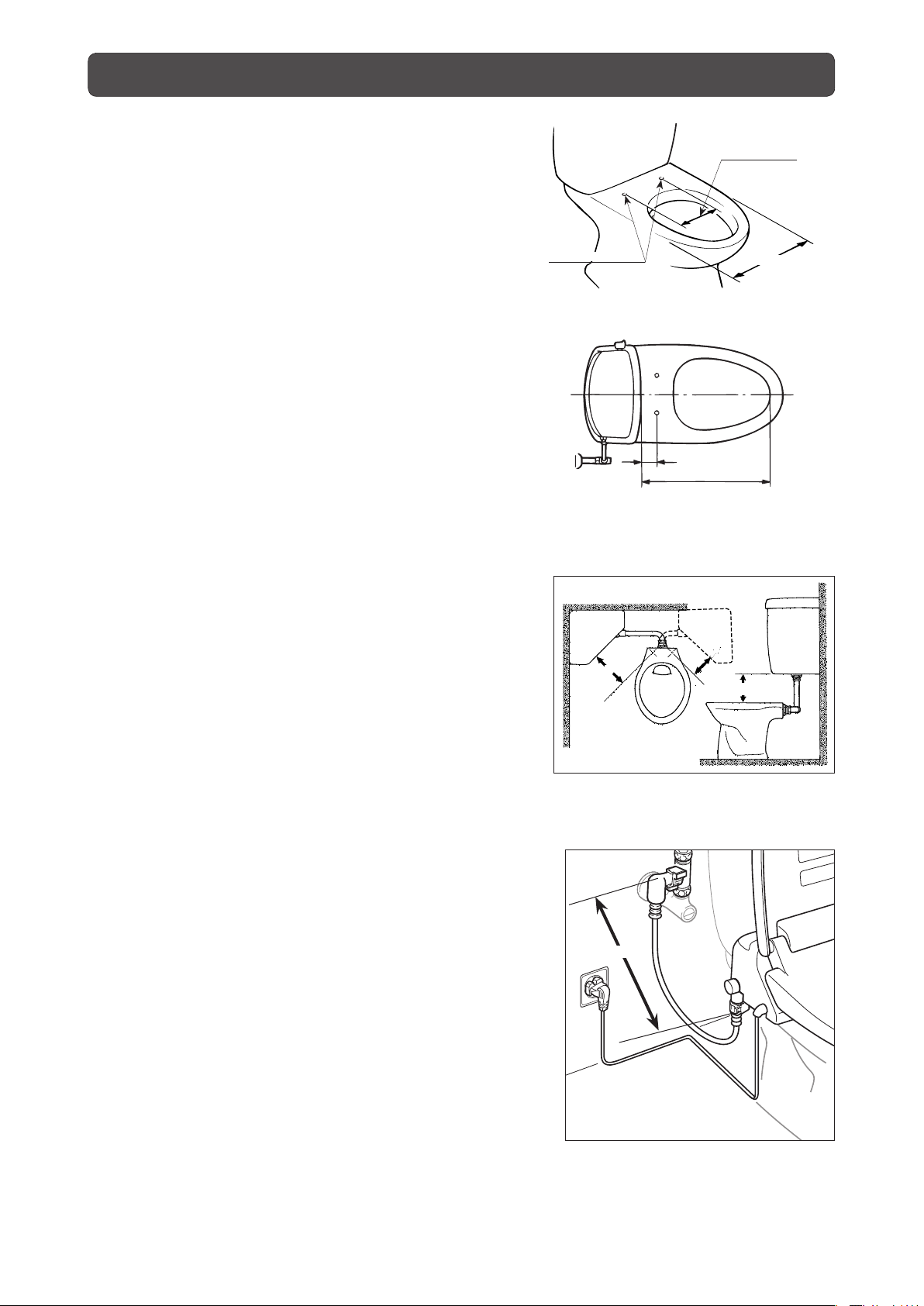
Checking the toilet
1. Measure the size of the toilet.
Depending on the toilet, it may not be possible to mount
this product on it.
Make sure the toilet's dimensions are as shown in the
figure at right.
14 to 15.7 cm
2.
In the case of a toilet with a corner
mounted tank, decide which is more
satisfactory, (1) or (2).
In the case of a corner mounted tank type toilet, it is
possible to mount this product if the dimensions A and B
meet the conditions in either (1) or (2) below.
(1) A: 17 cm or more
(2) A: 13 cm or more and
B: 17 cm or more
(3) A': 17 cm or more
(4) A': 13 cm or more and
B: 17 cm or more
If the measured dimensions satisfy neither (1) or (2),
(3) or (4), take measures such as raising the position
of the tank. (Please consult with the store where you
purchased this product.)
φ1.5 cm or more
A
80 cm or less
39 cm or less
5 cm or more
47 cm or more
A'
B
3. Conditions for use of this product's water
supply hose (packed with this product)
The length of the water supply hose shipped with this
product is 95 cm, but a length within 80 cm from the
junction fitting to the body's water supply socket is
appropriate. (See the figure at right.)
8
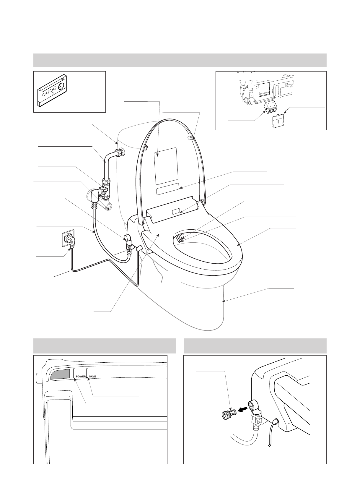
Names of parts
Overall view
<Bottom of body>
Remote control unit
(See page 10.)
Tank
Tank water supply pipe
Junction fitting
Water shutoff valve
Strainer
(See below.)
Water supply hose
Power plug
Caution label
Toilet seat lid
Deodorizer
cartridge cover
Deodorizer
cartridge
Marking label
Occupied seat sensor
Nozzle (for bidet)
Nozzle (for posterior)
Toilet seat
Body
Indicator panel
Power save lamp
Power lamp
Toilet bowl
Strainer
Strainer
* The strainer removes impurities and foreign matter in the
tap water. (See page 31.)
9
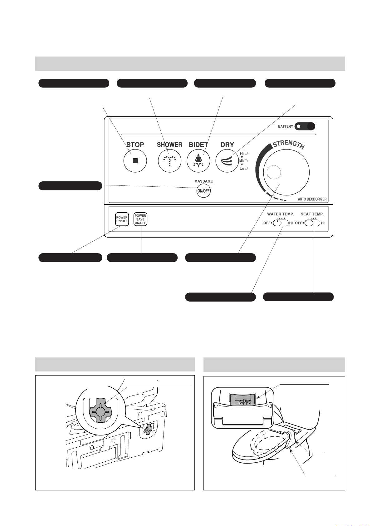
Operation panel
STOP
Stops posterior washing,
bidet washing, and drying
operations.
MASSAGE
Alternates spray strength
between strong and weak.
POWER
Pressing the stop switch
for 2 seconds or longer
turns the power on or off.
(See page 22.)
SHOWER
Use for posterior washing.
POWER SAVE
Pressing the toilet seat
switch and warm water
switch together for 2
seconds or longer turns off
the power to the toilet seat
heater and warm water
heater. (See page 26.)
BIDET
Use for bidet washing.
STRENGTH
Adjusts the spray strength
during posterior and bidet
washing. (See page 23.)
WATER TEMP.
Adjusts the water
temperature. (See page 22.)
DRY
Use when drying wet parts.
(See page 25.)
SEAT TEMP.
Adjusts the toilet seat
temperature. (See page 22.)
Warm water tank drain plug
<Bottom of body>
* Remove the warm water tank drain plug when draining the
water from the warm water tank. (See page 37.)
10
Warm water tank drain plug
Body locking plate
Body locking plate
Body
Lock lever
(See pages 33 and 34.)
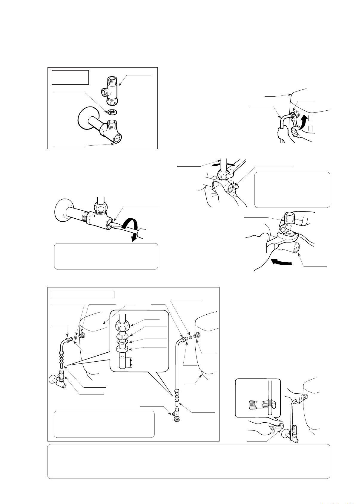
Installation
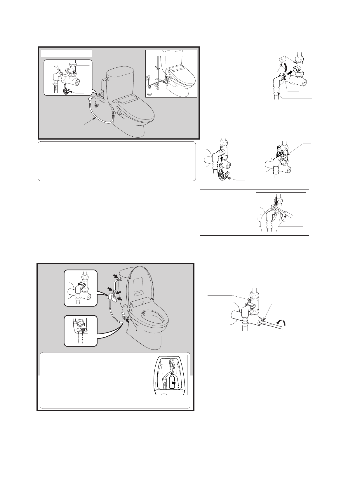
1. Installation of branch fitting
Installation
Branch fitting
diagram
Packing
(color: black,
thickness: 2 mm)
Water shutoff valve
(1) Close the water shutoff valve.
Close the water shutoff valve
for the toilet very tightly with a
flathead screwdriver (or the valve
handle, if available) and shut off
the water supply.
Water shutoff valve
Close
CAUTION
Close the water shutoff valve before performing any
•
operations.
* If you perform operations without closing the valve,
you may experience water leaks.
(2)
(3) Attach the
Remove the existing water supply pipe.
1) Loosen the cap nut at the tank.
A small amount of water
may spill from the pipe
when loosening the cap
Tank
Supply pipe
Cap nut
nut. If this is a concern,
please place a rag
underneath to catch
Loosen
the spilled water before
loosening the nut.
2) Loosen the cap nut at the water shutoff valve and
remove the water supply pipe.
Supply pipe
Loosen
Water shutoff valve
CAUTION
Do not apply unnecessary force
•
on the water shutoff valve or water
supply pipe.
* Doing so may break the
connections and cause water leaks.
Branch fitting
branch fitting.
Set the gasket seat
packing (color:
black, thickness: 2
mm) in the branch
fitting and attach
the fitting to the
water shutoff valve.
Water shutoff
valve
2. Installation of water supply pipe
Installation diagram
Gasket packing
(color: blue,
thickness: 2 mm)
Cap nut
Water supply from the wall
CAUTION
Please verify the orientation and the installation
•
sequence for each part.
* If you attach the parts in an incorrect sequence or
inappropriately, it may cause water leaks.
CAUTION
Please do not cut the guard area of the supply pipe.
•
•
Use a pipe cutter when shortening the supply pipe. Please connect the shortened pipe only after cleaning the cutting burrs by rinsing it with water or
some other method.
•
If the water shutoff valve can move vertically 5 mm or more, first please securely affix the stop valve.
* This may cause water leaks.
Ball tap
(or ball valve)
Guard area
Supply pipe
Branch fitting
Tank
Cap nut
Cap nut
Split compression
ring
Slip washer
Gasket packing
(color: black,
thickness: 4 mm)
Insertion tolerance
(10 to 15 mm)
Branch fitting
Gasket packing
(color: blue,
thickness: 2 mm)
Ball tap
(or ball
valve)
Guard
area
Tank
Supply pipe
Water supply from the floor
(1) Shorten the water supply pipe.
1) Mark the end of the water supply
pipe (on the side without the
guard) for a cutting position which
is suitable for attachment to the
branch fitting and then increase
that amount by an additional
10 to 15 mm for some insertion
allowance.
2) Cut the water supply pipe at the
position determined above with a
pipe cutter.
Add 10 to 15
mm for insert
allowance.
Pipe cutter
11
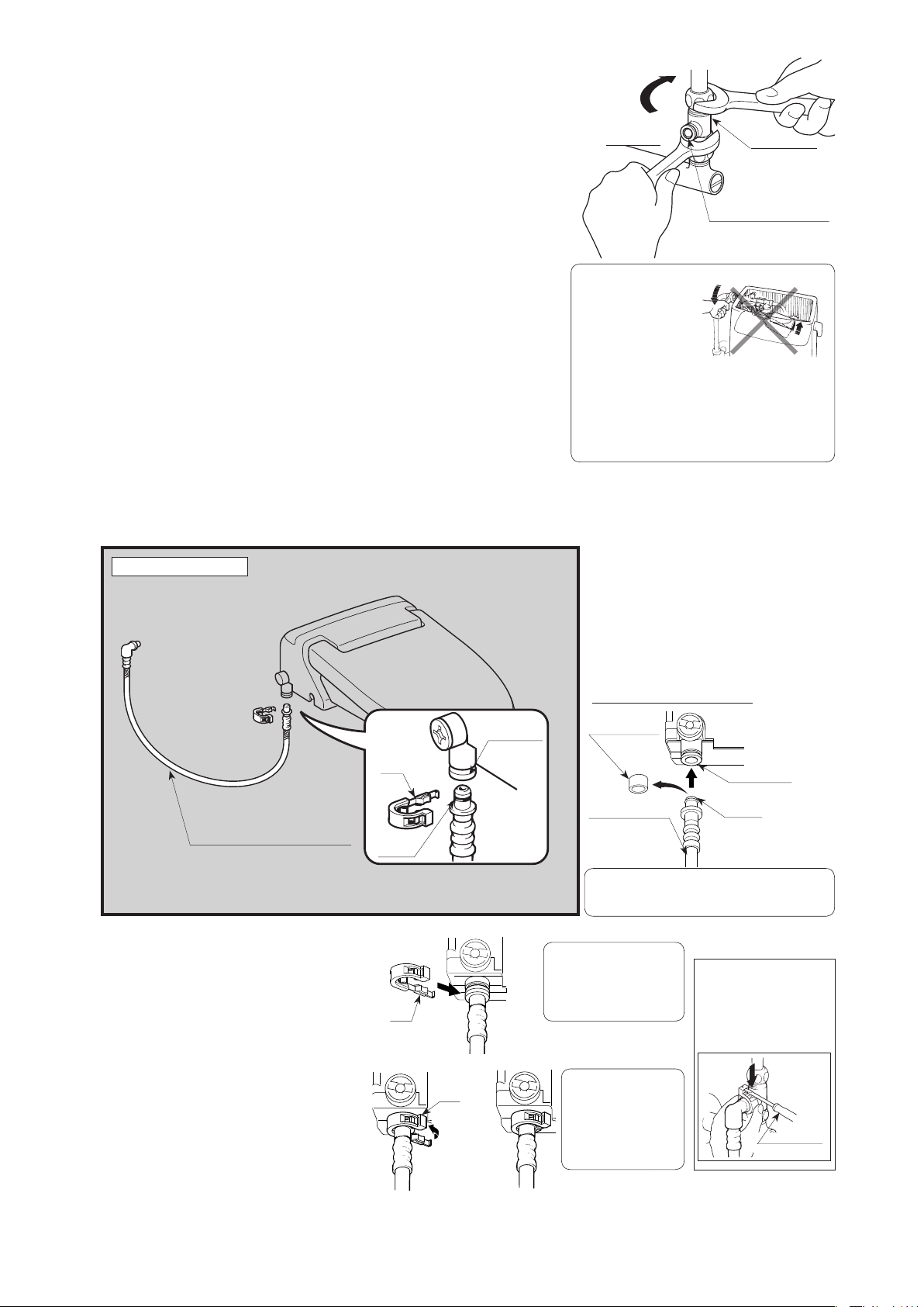
(2) Attach the water supply pipe.
1) Place the cap nut for the tank and branch fitting, split
compression ring, slip washer, and packing (color: black,
thickness: 4 mm) on the shortened water supply pipe and
insert the pipe into the branch fitting. (Please see the
above installation diagram of the water supply pipe.)
Supply pipe
Branch fitting
2) Place the gasket packing (color: blue, thickness: 2 mm)
between the ball tap and the supply pipe, and attach the
Hose connection socket
supply pipe to the tank with the cap nut.
3) The cap nut for the branch fitting should be fingertightened as much as possible, and then, additionally
tighten it with a wrench for another 3/4 to one full turn. Do
not over-tighten the nut.
(Tightening torque: 10 to 15 Nm ( 8-11 ft-lbs) or 100 to
150 KgF/cm)
While tightening the nut with a wrench, place a spanner
(monkey wrench) around the hexagonal area of the
branch fitting to hold it firmly, and then tighten the cap nut.
CAUTION
Tighten the cap nut
•
while securely grasping
the ball tap to prevent it
from turning.
* If the ball tap is rotated
out of position, the float
ball may make contact with the inside wall of the tank
and cause a water stoppage failure.
• Please be careful not to break or damage the hose
connection.
* Doing so may cause water leaks.
• Please firmly connect the water supply pipe.
* If the cap nut is not sufficiently tightened, it may
cause water leaks.
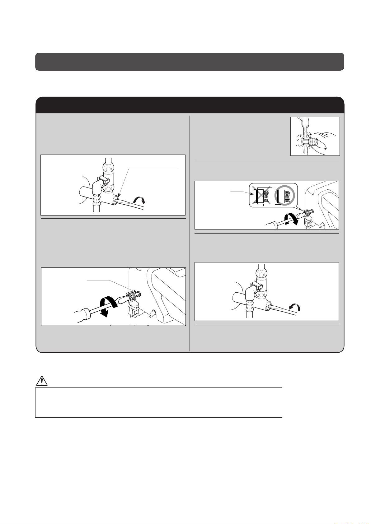
3. Installation of water supply hose to the shower
toilet (at the shower toilet body)
1)
Remove the protective cover
Installation diagram
from the end of the water supply
hose, and pull out the cap from the
water supply connection socket.
2) Connect the water supply hose
for the shower toilet into the water
supply connection socket.
Water supply connection socket
Water supply hose for shower toilet
3) Insert the attachment clip onto the
water supply hose to attach it to
the shower toilet and water supply
connection socket.
* The attachment clip can be attached in
any direction.
4) Bend the clip end and firmly clip
together both the feeding hose for
the shower toilet and the feeding
socket. After you install the clip,
twist it in both directions to verify
that it is firmly attached.
Clip
O-ring
Clip
Clip
Bend here
Water supply
socket
Protective cover
Water supply
socket
Water supply
hose for the seat
CAUTION
Please be careful not to damage the O-ring.
•
*If the O-ring is damaged, it may cause water leaks.
CAUTION
Please firmly insert the clip.
•
* If the clip is not firmly
inserted, it may cause
water leaks.
CAUTION
Please insert the clip
•
until you feel a click
from the clip edge.
* If not firmly inserted,
it may cause water
leaks.
O-ring
•
When removing the clip, hold
the clip with your fingers, set
the flathead screwdriver and
push the clip downward to
remove it as shown in the
figure below.
Flathead
screwdriver
12
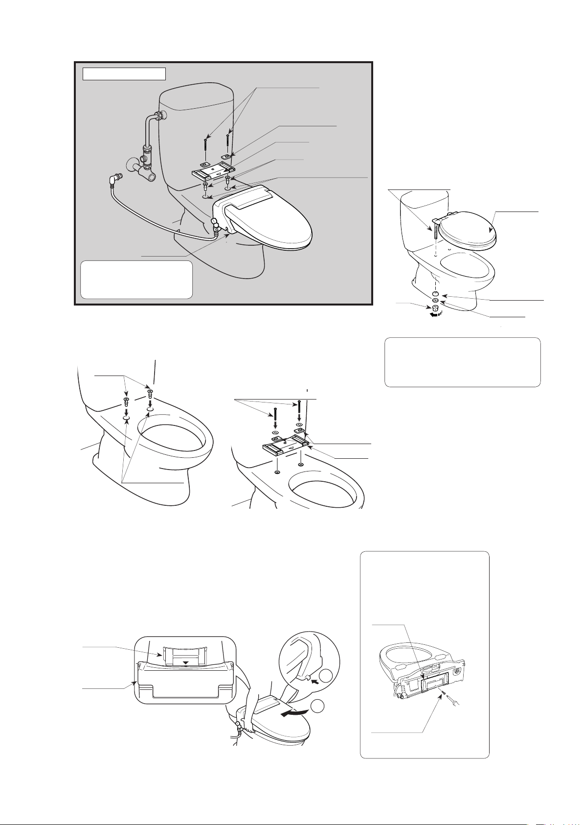
4. Installation of the shower toilet
Installation diagram
Shower toilet
Caution
•
When installing the shower
toilet, make sure to use the parts
provided in the installation kit.
(2) Attach the slide plate onto the seat.
1) Insert the bushings into
the seat mounting holes.
Bushings
Seat mounting bolts
Mounting brackets
Slide plate
Bushing
Toilet seat mounting guide holes
2) Insert the mounting
brackets into the slide
plate and attach the slide
plate with the mounting
bolts on the seat.
Mounting bolts for the toilet
(1) Remove the existing
seat.
1) Remove the nuts from the
seat mounting bolts, the
slip washers, and rounded
packing.
2) Raise the seat and remove
it by lifting the seat mounting
bolts.
Seat mounting bolts
Existing seat
Nut
Loosen
References
Some toilet seats may require different methods
•
of removal that differ from our explanation.
•
The removed toilet seat should be stored in your
home in case you remove the shower seat.
Rounded packing
Slip washer
Mounting brackets
Seat mounting holes
(3) Attach the shower toilet.
1) Place the shower toilet on the toilet and align the ▽
mark on the slide plate with the △ mark on the rear
section of the shower toilet.
2) Slightly raise the front side of the shower toilet, slide it
until the slide plate is fully inserted, and then press the
locking lever to secure the shower toilet.
Slide plate
Shower toilet
1
2
Slide plate
* For the attachment lacations of
the mounting brackets, please see
"Checking the toilet seat."
CAUTION
When use of the slide plate is not
•
necessary, please retain the slide
using the attaching screw included in
the installation kit to prevent it from
moving or becoming lost.
Slide plate
Attaching screw
13
5. Attachment of the water supply hose for the shower
toilet (at the branch fitting)
Installation diagram
O-ring
Water supply hose
for the shower toilet
CAUTION
Please be careful not to damage the O-ring.
•
* If the O-ring is damaged, it may cause water leaks.
•
Please firmly insert the clip.
* If the clip is not firmly inserted, it may cause water leaks.
•
Please insert the clip until you feel a click from the clip edge.
* If not firmly inserted, it may cause water leaks.
Branch
fitting
Clip
Example of water supply from the floor
(1) Remove the
protective covers
from the ends of
the water supply
hose and insert
the hose into the
branch fitting.
(2) Attach the clip in the same manner as
it is attached on the shower toilet, and
then attempt to twist the clip from side
to side to make sure that it is firmly
attached.
When removing the clip, hold
•
the clip with your fingers, set
the flathead screwdriver and
push the clip downward to
remove it as shown in the
figure below.
Clip
Branch fitting
Protective
covers
Bend here
O-ring
Water supply hose
Clip
Flathead
screwdriver
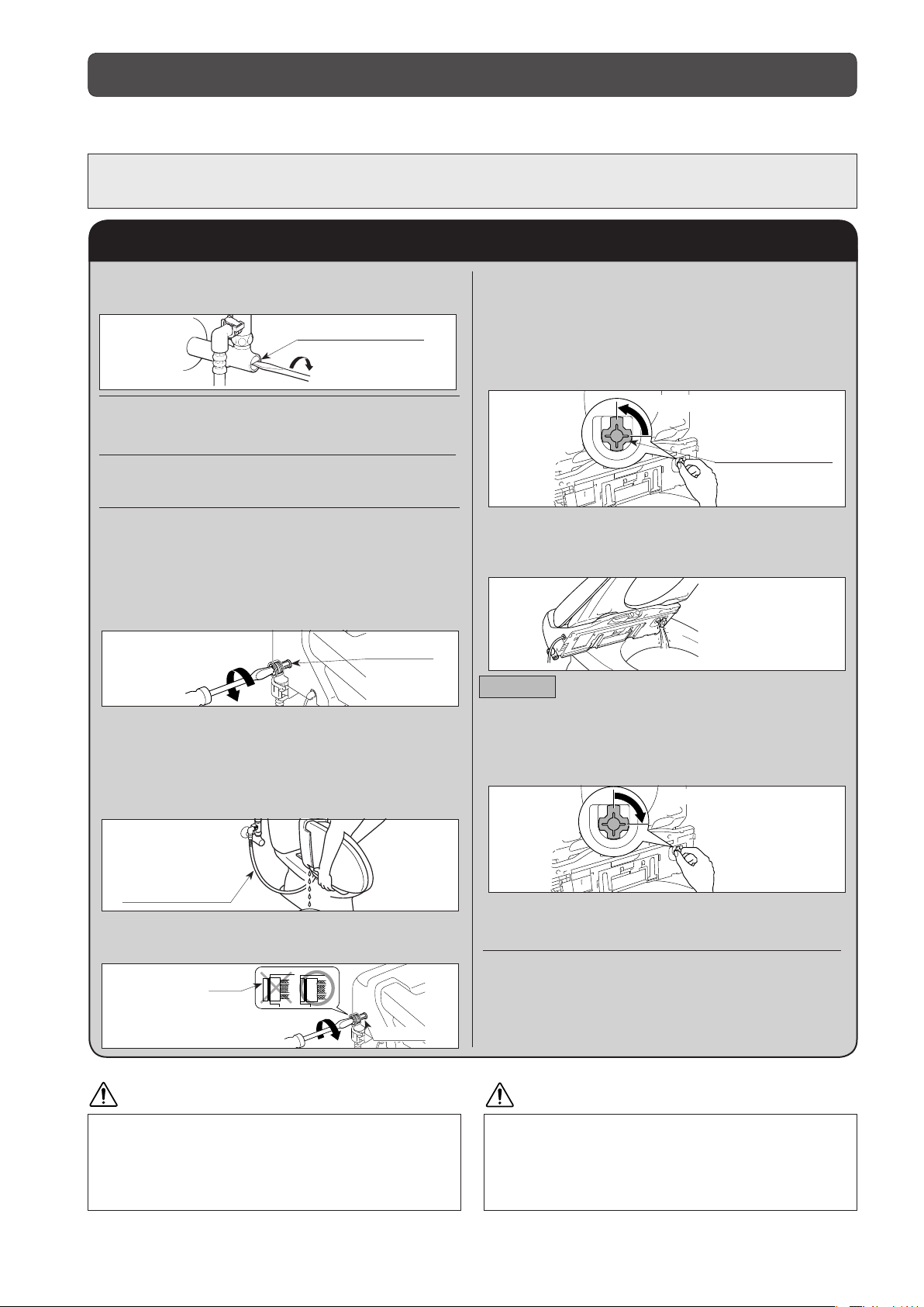
6. Confirming water flow
Branch fitting area
Water supply socket area
CAUTION
• When water supply into the tank does not stop, or the
tank does not fill at all, please check if the float ball is
making contact with the inside wall of the tank.
• If so, please reposition it using the following procedure:
(1) Loosen the inside nut on the side of the tank and
vertically straighten the ball tap.
(2)
While holding the ball tap with your hand, tighten the nut.
• Please do not remove the strainer while the water shutoff valve is open.
• Doing so may cause water leaks from the strainer area.
(1) Turn the water shutoff valve
counterclockwise to open the supply
of water to the tank and shower toilet.
Branch fitting
Water shutoff valve
Turn counterclockwise.
(2) Operate the flush handle attached on
the tank and check each joint to see if
there are any water leaks.
* If water is leaking, further tighten the
connections, or re-install the shower toilet.
(3) Confirm that the water flow stops after
the tank is filled with water.
* If the tank does not fill with water, or the
water flow does not stop, please check
whether the ball tap and float ball are
functioning.
14
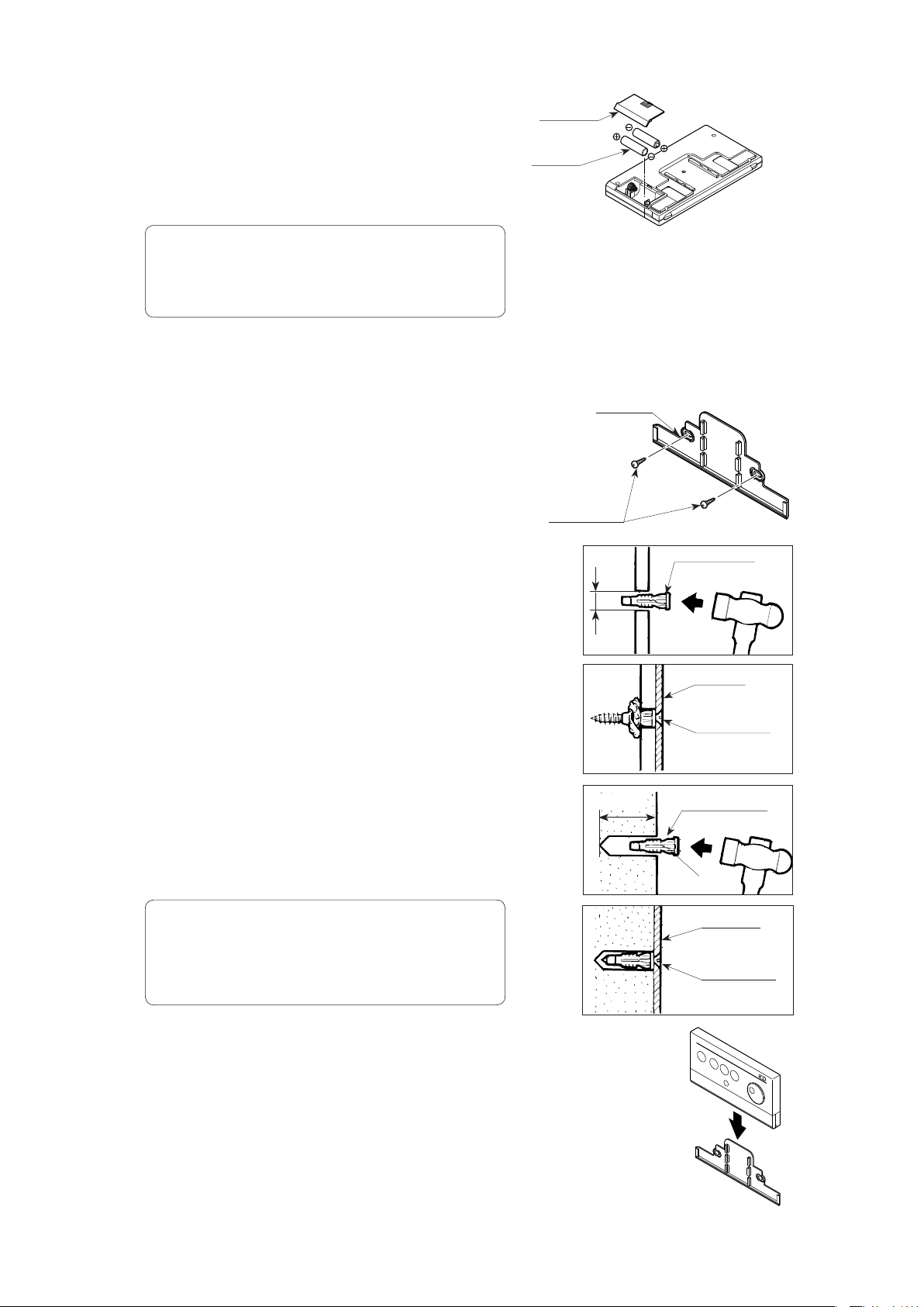
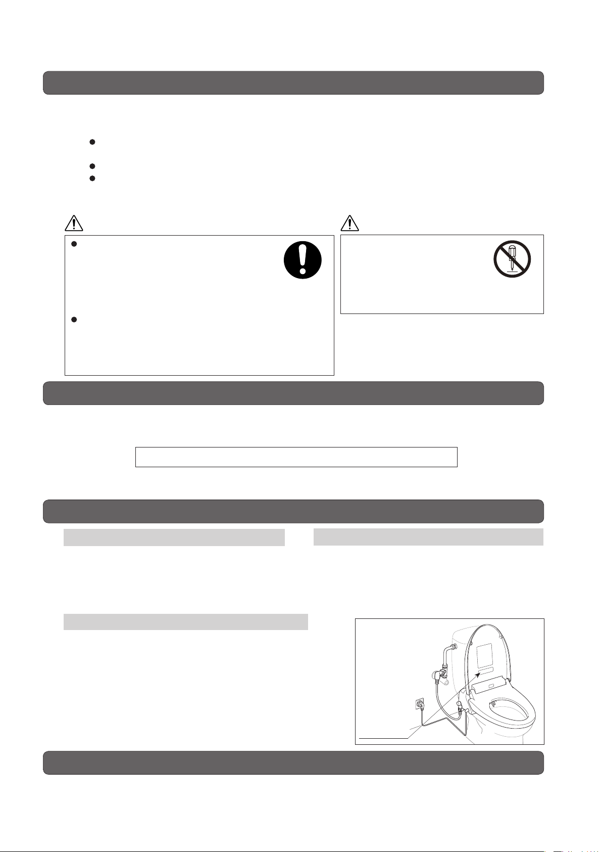
7. Positioning the remote control unit
(1) Open the back cover of the remote control
unit and insert the batteries (two AA size
batteries).
(2) Place the remote control unit in the position
you would like it to be in, sit down on the toilet
seat and press the stop switch.
CAUTION
•
Install the batteries with the positive and negative poles facing the
correct direction in accordance with the marks on the remote control unit
case.
•
Do not use old and new batteries together.
•
Use the batteries in the pack.
8. Mounting the remote control
(1) Place the bracket on the wall depending on the
wall material as follows, then mount it in the
desired mounting position.
• If mounted in plywood paneling 5 mm or
greater in thickness:
Fasten the bracket to the wall with the wood
screws.
• If mounted either in plywood paneling 5
mm or less in thickness or in gypsum
board:
Back cover
Battery
Wood screw
Bracket
6 mm dia.
Plastic anchor
A) In plywood paneling, drill holes with a
diameter of 6 mm; in gypsum board, drill
holes with a diameter of 5 mm.
B) Using a hammer, gently drive the plastic
anchors into the holes.
C) Fasten the bracket securely to the
anchors using wood screws. As you
tighten the screws, they are hard to turn at
fi rst, then gradually get easier to turn, and
then are hard to turn again.
(2) Align the remote control unit with the bracket
and then push it down onto the bracket.
CAUTION
Water will spray from the nozzle if the Shower or Bidet switch is pressed,
•
so exercise caution.
•
Check to make sure there is enough space above the remote controller to
mount or remove the controller at its mounting position.
•
After you make sure the power lamp blinking, pull the power plug out of the
receptacle at once.
33 mm
Remote
control unit
Bracket
Wood screw
Plastic anchor
φ6mm
Bracket
Wood screw
Bracket
15

Trial operation
(Follow the procedure below after installation work is completed.)
1. Insert the power plug in the outlet.
Confi rm that the power lamp on the body is lit.
220V
Power plug
2.Check the shower and bidet spray.
(1) Check the shower washing operation.
1) With your forearm resting on the toilet
seat, press the SHOWER button.
The shower automatically stops in two
minutes after the switch is turned on.
2) When the nozzle extends, cover the tip
of the nozzle with your hand to catch the
spray when the shower begins spraying.
3) Press the STOP button to stop the shower
spray.
Roll up your sleeve and
bring your bare arm in direct
contact with the toilet seat.
(2) Perform the same check with the bidet spray
function.
STOP
Stops posterior washing,
bidet washing, and drying
operations.
MASSAGE
Repeats washing
strength weak-strong
cycle.
POWER
Flushes the toilet
automatically when you
rise from the toilet seat.
POWER SAVE
Saves power by lowering
the toilet seat temperature.
DRY
Used to dry the parts
that became wet during
washing.
WATER TEMP.
Adjusts the temperature of
the shower and bidet water.
*Since there is an occupied seat sensor, the
product’s shower, bidet and deodorizing functions
will not operate if you don't touch the seat.
STRENGTH
Adjusts the spray strength
during posterior and bidet
washing.
SEAT TEMP.
Adjusts the heated toilet
seat temperature.
CAUTION
When removing the strainer, be sure
to close the water shutoff valve. When
attaching the strainer, firmly tighten it until
the end of the strainer is hidden in the body.
* Water will leak from the strainer.
Strainer
End
Warning
Please make certain to
securely attach the ground wire.
* If not connected, there is the
risk of electric shock in case of a
failure.
* If there is no ground terminal
on the electrical outlet, please
consult an electrician.
16

3. If flushing begins to weaken,or if the shower spray
seems to be getting weaker, clean the strainers.
(1) Turn the water shutoff valve to the right to close it.
As the water shutoff valve is pre-adjusted, remember the
original position (how much it is turned).
(2) Remove the strainer on the left side of the body.
Place a wash bowl or similar underneath the strainer.
(3) Clean the strainer.
(4) Firmly tighten the strainer.
(5) Turn the water shutoff valve to the original position to open it.
4.
If freezing weather is anticipated before handing the
Water Shutoff
Valve
Strainer
Turn
clockwise.
product to the customer, drain the water.
(1) Turn the water shutoff valve to the right to stop water supply to
the tank.
(For cold area drain type, operate the indoor drain plug.)
(2) Press the flush lever on the tank to drain water from the tank.
(3) Remove the power plug from the outlet.
(4) Drain water from the hot water tank and the water supply hose
connected to the body.
1) Pull the lock lever on the right side of the body and slide the
body forward to remove it from the toilet bowl.
2) Remove the strainer on the left side of the body. Place a wash
bowl or similar underneath the strainer.
3) Tilt the body to the left to drain water from the water supply
hose through the strainer hole.
4) After water drainage, firmly attach the strainer.
5) Turn the drain plug on the bottom of the body to the left
(counterclockwise) 90 degrees to loosen it.
6) Tilt the body forward, pull out the drain plug and drain water
from the hot water tank completely.
7) After water drainage, push and turn the drain plug to the right
(clockwise) 90 degrees to tighten it.
8) Place the body on the toilet bowl, and engage the ▽ mark on
the mounting plate with the convex part at the lower rear of the
body.
9) Slide the body backward and push the lock lever to secure the
body.
Lock Lever
Strainer
Turn
clockwise.
Drain Plug
Loosen
mark of the Fixing Plate
▽
Convex part of the
back of the body
17

4.
Using this product
Safety precautions
Observe these precautions to prevent possible injury or damage.
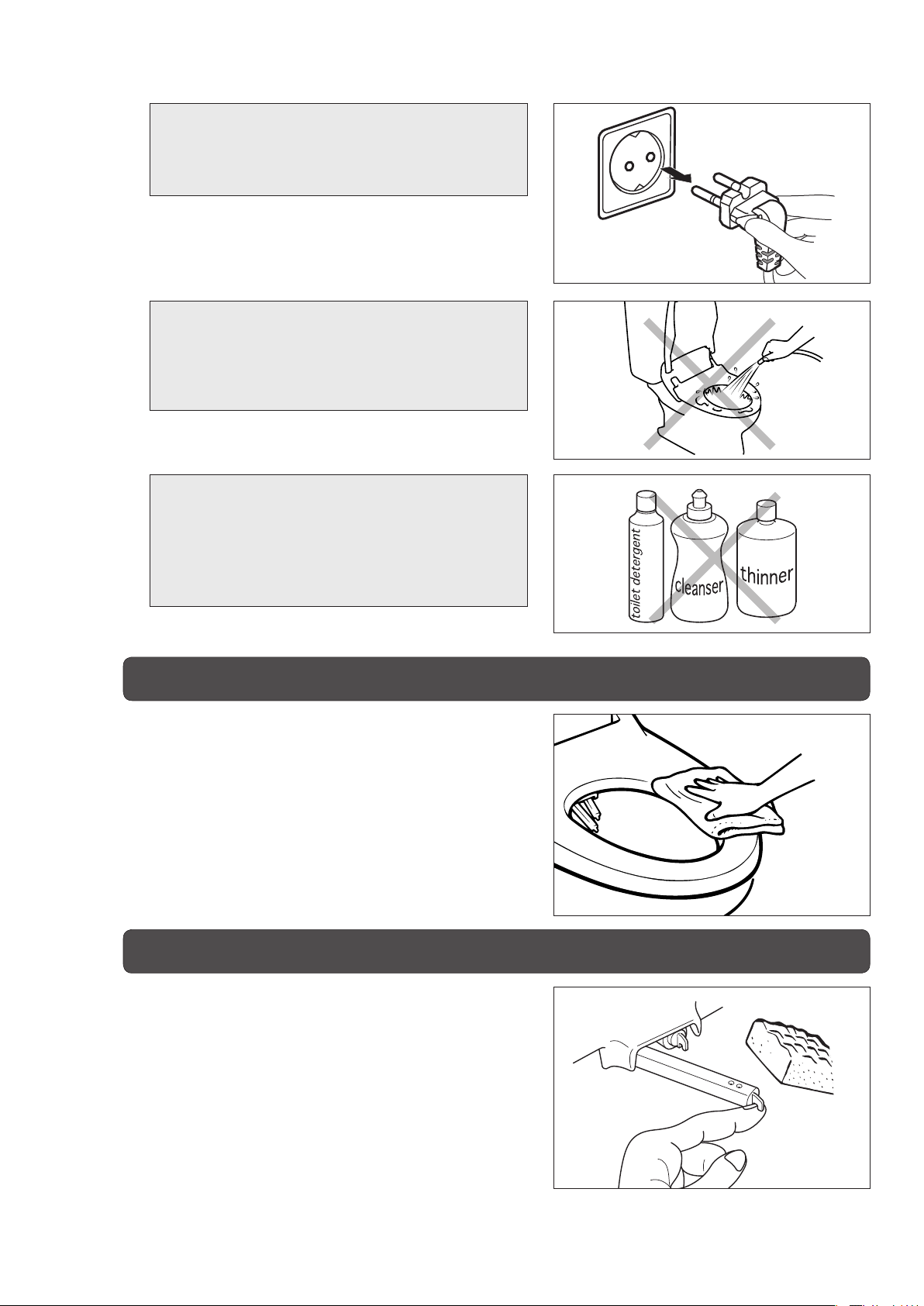
Do not pull the power plug out of the wall
outlet by pulling on the power cord. This could
damage the power plug or power cord and
cause an electrical hazard.
Do not climb or seat on top of the toilet seat
lid or body. Doing so could damage it.
For care of plastic parts, do not use any
cleansers which are not safe to use on
toilet seats. (Do not use toilet bowl cleaner,
household cleaner, bleach, benzene, paint
thinner, polishing powder, or cresol.)
Do not open or close either the toilet seat lid
or the toilet seat with great force. Doing so
could crack or otherwise damage it, causing
an electrical hazard.
Do not lean against the toilet seat lid during use.
Doing so could damage it.
Do not forcefully pull on the nozzle or turn it.
Doing so could damage it.
18
Do not cover the warm air outlet or insert a
foreign object into it. Doing so could cause
product failure.
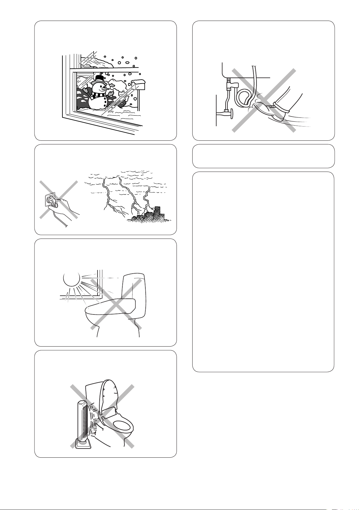
If there is risk of water lines freezing,
implement the freeze prevention methods to
prevent damage. (See page 35.)
Do not apply unnecessary force to the body
water supply hose. Doing so could damage it
and cause water to leak.
In a thunderstorm, do not touch the power plug.
Doing so could cause an electrical hazard.
Do not expose this product to the direct
rays of the sun. Plastic parts could become
discolored by the sunlight.
Do not place a stove or heater close to
the body. Doing so could cause product
discoloration or failure.
Do not urinate on the nozzle. Doing so could
cause nozzle damage or failure.
If you are using this product for a long period of
time, set the seat temperature switch
on "Off".
For the following persons, be sure to set the
seat temperature switch on "Off" when they are
using this product.
(Children, elderly persons, persons who are
sick, persons who cannot adjust the temperature
themselves, persons with weak skin, persons
who are taking medicines that make them
drowsy, such as sleeping medications, deeply
intoxicated persons, or persons who are
extremely fatigued.)
* If this product is being used for a long
period of time with the seat temperature switch
on any setting other than "Off", there is
danger of low temperature burns.
About Low Temperature Burns
A burn occurs when the skin has been
exposed to high temperatures. However, a low
temperature burn may occur when the skin
has been in contact with an object at relatively
low temperature (about 40ºC). Susceptibility
to burns also depends on an individual’s skin
sensitivity and other factors.
19

Other references
A toilet seat cover or toilet seat lid cover can
cause the occupied seat sensor to either remain
on continuously or not go on at all, leading to
faulty operation. In this event, remove the cover.
• The capacity of the warm water tank is 0.88 L.
Water temperature gradually drops when the
wash or bidet is used. If the water drops below
a comfortable temperature, press the stop
button and wait about 3 minutes for the water to
reheat.
• The water temperature range is preset to the
following temperatures:
Low: Approx. 36 °C,
Medium: Approx. 38 °C,
High: Approx. 40 °C.
It takes approximately 10 minutes to heat
cold water (at about 5 °C) to the appropriate
temperature (about 38 °C).
To prevent the toilet seat and toilet seat lid
from slamming down, a damping mechanism is
provided to lower them gradually. If the toilet seat
or toilet seat lid is closed roughly or too forcefully,
this product could be damaged or fail.
Before and after washing and when the water
temperature adjustment button is pressed, etc.,
water is sprayed out around the nozzle, but this
is necessary due to this product's construction
and is not a sign of breakdown.
If water sprays under any other circumstances,
or sprays constantly, close the water shutoff
valve and remove the power plug from the
wall outlet. Then, contact the store where you
purchased this product.
This product is equipped with an occupied seat
sensor that prevents the water from spraying
and the dryer from operating if nobody is sitting
on the toilet seat. This prevents activation if the
wash, bidet, or dry button is pressed when the
toilet seat is unoccupied.
Occupied seat sensor
This product is constructed to use the tap water
pressure to extend the nozzles and spray water
from them. Where the tap water pressure is
extremely low, the nozzles may not spray water
at all with the spray strength at the weakest
setting. In this case, turn the STRENGTH dial
clockwise. (See page 23.)
While this product is still new, there may be a
slight odor when using the drying function. As
the toilet is used, the odor will disappear.
This product may interfere with radio or
television reception. In this case, move the radio
or television away from this product until the
interference ceases.
The occupied seat sensor uses light reflection
to function and may not operate in the following
cases:
• You are leaning forward or sitting on the front of
the seat.
Sit back fully on the toilet seat, or change the
way you sit on the toilet.
• You are wearing clothing that is black, napped,
or otherwise inhibits light reflection.
Cover the sensor with your hand or arrange
your clothing so that your skin is sensed by the
sensor.
• Dirt or water is on the sensor.
Remove the dirt or water from the sensor.
Sit back fully on the toilet seat and arrange your
clothing so it does not get wet when using the
wash or bidet functions.
20

Using this product functions
《Remote control unit》
■
Main operation panel
SHOWER
Use when washing your
posterior.
Press again for wide range
washing.
(See page 23.)
BIDET
Use for bidet washing.
Press again for wide range
washing.(See page 23.)
Top
Front
Dependingonthemodel,somefunctions(markedwithastar,☆ )maynotbeincluded.
DRY
Blows air for drying.
(See page 25.)
Remote control transmitter
STOP
Stops the
SHOWER, BIDET
and DRY functions.
■
Sub-operation panel
POWER
Turns the power to the
Shower Toilet main unit ON/
OFF.
(See page 22.)
MASSAGE
Alternates spray
strength between
strong and weak.
(See page 24.)
Open the cover of the remote control unit.
POWER SAVE
Saves power by lowering
the toilet seat and water
temperatures.
(See page 26.)
SPRAY STRENGTH
Adjusts the spray strength
during posterior or bidet
washing.
(See page 23.)
WATER TEMP.
Adjusts the water
temperature.
(See page 22.)
* The deodorizer fan operates automatically. (See page 25.)
Battery indicator
This picture appears when
the battery power is low.
(See page 38.)
SEAT TEMP.
Adjusts the temperature of
the heated toilet seat.
(See page 22.)
21

《Preparations before use》
For an even more comfortable use, check the
following operations before using this product.
■
POWER
Press the POWER button to turn the power ON or OFF.
*
If the power is ON, the power lamp on the indicator panel will light
up.
* When you insert the power plug into the power outlet for the first
time after purchasing this product, the power is automatically set to
"ON".
(Turning the power on/off)
■
WATER TEMP.
(Heating the
shower)
Adjust the temperature of the shower
using the WATER TEMP. switch.
The water temperature can be set to one of 4
settings: HI, MID, LO and OFF. Set it to your
preferred temperature.
WARNING
•
If you are using this product for a long period of time, set
the seat temperature to OFF.
• For the following persons, be sure to set the seat
temperature to OFF when they are using this product.
(Children, elderly persons, persons who are sick,
persons who cannot adjust the temperature themselves,
persons with weak skin, persons who are taking
sleeping medications or other medicines that make them
drowsy, deeply intoxicated persons, or persons who are
extremely fatigued.)
* If this product is being used for a long period of time with the
seat temperature set to any setting other than OFF, there is
danger of low temperature burns.
■
SEAT TEMP. (Heating the toilet seat)
Adjust the temperature of the toilet seat
using the SEAT TEMP. switch.
The seat temperature can be set to one of 4 settings:
HI, MID, LO and OFF. Set it to your preferred
temperature.
Reference
• The toilet seat will not become warm instantly. If
you turn the SEAT TEMP. switch 10 to 15 minutes
before use, the toilet seat temperature will be at a
comfortable level during use.
• This product is equipped with a "Seat Heater AutoOff" function that prevents low temperature burns
by automatically switching the toilet seat heater off
when it is occupied.
(See page 27.)
• The toilet seat temperature (set at medium) can be
decreased (2°C). (See page 27.)
22

《How to use basic functions》
■
Shower
A shower is sprayed from the tip of the nozzle,
and washes your posterior.
Press the shower button.
1 1
■
Bidet
A shower is sprayed from the tip of the
nozzle, and sprays the more delicate female
parts.
Press the BIDET button.
Press the STOP button to stop
3
CAUTION
• In places with low tap water pressure, the nozzles may
• Please sit fully on the toilet seat. If you sit fully on the
the spray.
* An automatic self-stop function is included
which stops both posterior and bidet washing
automatically after 2 minutes.
not spray water far enough if the spray strength is set
to LO. In such cases, try setting the spray strength to
HI first.
seat, there will be less water splashing.
Turn the STRENGTH dial to
2
adjust the spray strength.
The STRENGTH dial has 5 levels. Set it at the
strength you prefer.
To make the
strength weaker,
turn the dial
counterclockwise.
Reference
You can make the washing strength much weaker or
stronger beyond the dial range.
(See page 28.)
To make the
strength
stronger,
turn the dial
clockwise.
23

■
Posterior massage washing
Spray strength is alternated between strong and weak during posterior washing to provide a
massaging effect.
Press the MASSAGE button
1
during posterior washing.
To stop the massage spray, press
2
the MASSAGE button again.
* Massage effect varies depending on the washing strength. This is high and low when the washing strength is High and
Low respectively.
24

■
Drying
Warm air will be blown out, and dry the parts which were wet by the shower.
Press the DRY button again to
Press the DRY button.
1
* Deodorizing is stopped temporarily while the drying
function is used.
change the temperature of the
2
warm air.
The warm air temperature setting is arailble
in 3 steps of "Hi" "Mid" "Lo". Set it at the
temperature tou prefer.
*
Each time the button is pressed, the indicator changes
from “High” to “Medium” to “Low,” then back to “High.”
WARNING
•
If you are using the drying function for a
long period of time, set the DRY mode to
LO.
• For the following persons, be sure to
set the DRY mode to LO when they
are using this product:
(Children, elderly persons, persons who are
Press the STOP button to stop
3
the drying function.
* An automatic self-stop function is included that stops
drying automatically after 4 minutes.
Reference
• To speed up the drying process after using one of the wash functions, wipe lightly with toilet paper to remove any drops
of water, and then press the DRY button.
• This product is equipped with a "low drying temperature start" function which switches the drying temperature from the
high temperature starting pattern to the low temperature starting pattern. (See page 27.)
sick, persons who cannot adjust the temperature
themselves, persons with weak skin, persons who
are taking sleeping medications or other medicines
that make them drowsy, deeply intoxicated
persons, or persons who are extremely fatigued.)
* If the drying function is being used for a long period of
time with the DRY mode on any setting other than LO,
there is danger of burns.
COMPULSORY
■
Deodorizing
Deodorizing starts when a
1
person sits on the toilet seat.
* This product is equipped with a deodorizer cartridge
which absorbs odors from the toilet. (See page 30.)
* Deodorizing is stopped temporarily while the drying
function is used.
Deodorizing automatically stops
2
1 minute after you stand up.
Stops after 1 minute
■
To disable the deodorizing function
Press the STOP and BIDET buttons
simultaneously for 2 seconds or longer.
* When operation is accepted, the power lamp on
the body blinks momentarily and the deodorizing
fan is not activated even when you are seated on
the toilet.
* To continue to use the function, again press the
STOP and BIDET buttons simultaneously for 2
seconds or longer.
Press the buttons simultaneously for 2 seconds or longer.
25
25

《How to use convenient functions》
Set
Temperature
8:00
10:00
12:00
14:00
16:00
18:00
20:00
22:00 24:00
Set
Reheat
Power Save
Temperature
Seat Temperature
OFF
8 hours
■
Power save
One-Touch Power Save: Controls power consumption by turning off the toilet seat heater for a
period of 8 hours overnight or during other extended periods when this
product is not being used. The settings automatically revert after 8 hours.
One-touch power save (8 hours)
Press the POWER SAVE button.
1
(The power save lamp will light up.)
For example: when One-Touch Power Save is set for 10:00
* Once 8 hours have passed, the settings will automatically return to their original state, and the power save lamp will
change from blinking to off.
* Pressing the One-Touch POWER SAVE button sets the timer for 8 hours. This highly convenient function allows as
many settings daily as desired, e.g. morning setting, nighttime setting, etc.
* When the One-Touch Power Save
function is running, the power save
lamp lights up.
To cancel the One-touch power save
function, press the POWER SAVE
2
button again.
(The power save lamp will go out.)
* You can use the toilet even when the power save function is operating. However, you may feel water is cold as the
heater for water and the toilet seat is turned off. If you feel so, cancel the power save function.
* Even when the power save functions are not operating, leaving the toilet lid closed is an effective way to save power.
26
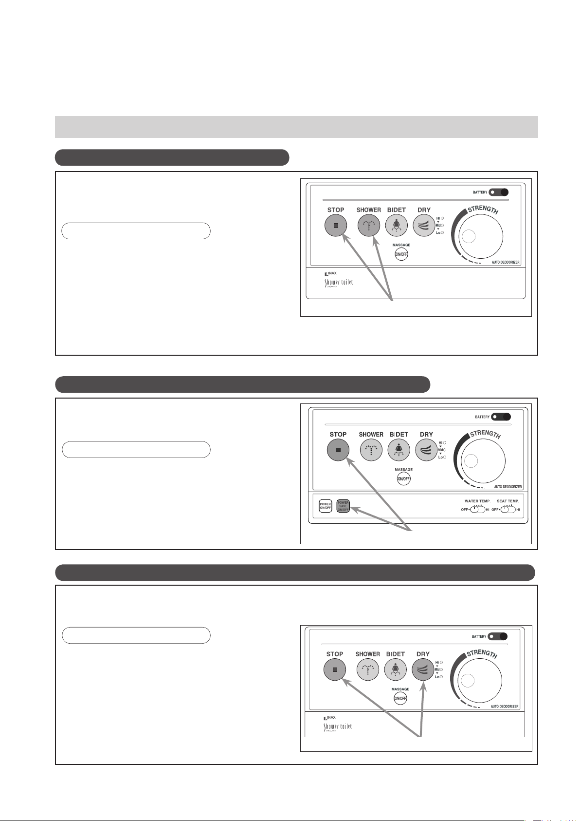
■
Other convenient functions
Seat heater auto-off
This product is equipped with a function that
prevents low temperature burns by automatically
switching the toilet seat heater OFF when it is
occupied. Follow the procedure below.
■
Setting and canceling
• Press the STOP button and the POWERFUL
shower button simultaneously for 2 seconds or
longer.
(Once the function has been set, you will hear a
"beep, beep" sound.)
• This function can be canceled by following the
same procedure.
If you use the toilet continuously with this function enabled, you may feel the toilet seat is lukewarm.
* The toilet seat heater automatically turns ON when you stand up.
Press the buttons simultaneously for 2 seconds or longer.
Changing the (medium) temperature setting of the seat
The seat temperature (medium) can decreased by
2°C in the following procedure.
■
Setting or canceling
•
Press the STOP button and POWERSAVE
button simultaneously for 2 seconds or longer.
(Once set, an indicator on the body will blink as
soon as the function has been set.)
• Medium temperature change can be cancelled in
the same method.
Press the buttons simultaneously for 2 seconds or longer.
Low drying temperature start function (when equipped with drying function).
The dry function can be set to start on the low temperature setting. This function is convenient
for elderly persons, handicapped persons or persons who are particularly sensitive to heat. Use
the following procedure to enable or cancel the toilet seat heater auto off function.
■
Setting or canceling
•
Press the STOP button and DRY button
simultaneously for 2 seconds or longer.
(Once set, an indicator on the body will blink as
soon as the function has been set.)
• Medium temperature change can be cancelled
in the same method.
* Each time the button is pressed, the indicator changes
from “Low” to “High” to “Medium,” then back to “Low.”
Press the buttons simultaneously for 2 seconds or longer.
27

Making the spray strength still milder
If the "LO" setting for the shower spray is still too strong, adjust the spray strength using the
following procedure.
■
Setting and canceling
• Press the BIDET button and the POWER SAVE
ON/OFF button simultaneously for 2 seconds or
longer.
The power lamp on the body blinks momentarily
and the spray strength will weaken one step.
There are two weak settings. Adjust the spray to
your preferred strength.
To make the spray strength weaker, press the
The spray strength weakens one step
each time the buttons are pressed.
The original spray strength will be
restored on the third time.
buttons simultaneously for 2 seconds or longer.
* In places with low tap water pressure, the nozzles
may not extend or it takes time longer than usual
for the nozzle to extend, if the spray strength is
set to the lowest.
• To restore the original spray strength, repeat the process of pressing the BIDET button and the
POWER SAVE ON/OFF button simultaneously for 2 seconds or longer. The original spray strength
will be restored on the third time.
* Operate the buttons twice when weakened one step; once when weakened two steps.
The power lamp on the body blinks momentarily each time the buttons are pressed.
For persons who would like to make the spray strength much stronger
Persons who think the "strong" setting for the shower spray is still too weak can adjust the spray
strength using the following procedure.
The “strong” setting can be further strengthened.
■
Setting and canceling
• Press the SHOWER button and the POWER SAVE
ON/OFF button simultaneously for 2 seconds or
longer.
The power lamp on the body blinks momentarily
and the spray strength will be strengthened one
step.
Press the buttons simultaneously for 2 seconds or longer.
• To restore the original spray strength, press the SHOWER button and the POWER SAVE ON/OFF
button simultaneously for 2 seconds or longer.
The power lamp on the body blinks momentarily each time the buttons are pressed.
28
Maintaining this product
WARNING: When maintaining this product,
remove the power plug from the
wall outlet. Failure to do so could
result in electric hazard or fire.
WARNING: Do not pour water or cleanser in
the body. Do not splash water or
cleanser on the body or on the
power plug. Doing so could result
in electric hazard or fire.
WARNING: For care of plastic parts, do not
use any cleansers which are not
safe to use on toilet seats.
use toilet bowl cleaner, household
cleaner, bleach, benzene, paint
thinner, polishing powder, or cresol.)
(Do not
Cleaning the body
Periodically, wipe off the body with a soft cloth
dampened with water.
Cleaning the nozzles
Pull out the nozzle and clean it with a sponge.
Do not forcefully pull on the nozzle or bend it.
2929
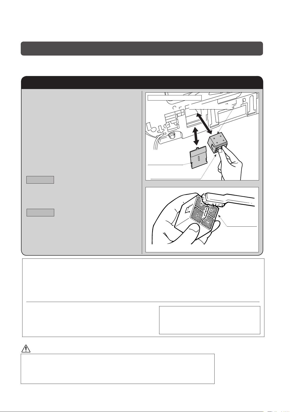
How to clean the deodorizing cartridge
The deodorizing cartridge may perform poorly if covered with dust. If odors start to bother you, please
clean the cartridge.
How to clean the deodorizing cartridge
1. Disconnect the power plug from the
outlet.
2. Remove the seat from the toilet (see
page 13).
3. Open the cover that is over the
deodorizing cartridge, which is
installed on the underside of the
seat.
4. Remove the deodorizing cartridge.
5. Clean off any dust covering the
cartridge filter with a tool such as
toothbrush.
CAUTION
Be careful! Do not wash the deodorizing
cartridge or allow it to become wet!
6. Hold the deodorizing cartridge with
your fingertips and insert it into the
opening, and then replace the cover.
CAUTION
Caution: Please insert the deodorizing
cartridge into the opening using the
orientation positioning as shown in
the diagram to the right. (Position the
rounded corners up.)
Underside of the toilet seat
Deodorizing cartridge
Cover of the opening
that contains the
deodorizing cartridge
Please make sure the
cartridge orientation is correct.
Cartridge filter
7. When cleaning is complete, reinstall
the toilet seat (see page 13).
Replacing the deodorizing cartridge
If odors still bother you after cleaning the cartridge filter, the deodorizing cartridge has expired. Please
replace it with a new cartridge. The useful life of the deodorizing cartridge is approximately seven
years under normal use.
* The useful life of the deodorizing cartridge is based on average hours of use by a family of four, two males and two
females.
First, please record the date you begin using the shower
toilet in the box to the right, and use this as a guide for
replacing the deodorizing cartridge.
Please record the date you replace the deodorizing
cartridge on the label attached to the cartridge.
Please write down the date you started using the shower toilet.
Year Month Day
CAUTION
The deodorizing fan is installed behind the opening for the deodorizing cartridge.
Please do not place your finger or anything other than the deodorizing cartridge into the
opening.
*Doing so may cause a finger injury or an equipment failure.
3030
Cleaning the strainer
If the spray strength weakens over time, clean the strainer using the following procedure.
Cleaning the strainer
1. Close the water shutoff valve to cut
off the water supply.
Since the water shutoff valve is adjusted beforehand,
keep the original position (to what extent you turned
the valve) in mind.
Water shutoff valve
Turn clockwise.
2. Turn the strainer on the bottom left of
the body with a screwdriver or similar
tool and remove it.
A small amount of water will pour out at this time.
Place a wash bowl or similar container underneath to
catch the water.
Strainer
3. Remove the dirt
adhering to the inside of
the strainer by rinsing it
with water.
4. Install the strainer, tightening it fully
with a screwdriver or similar tool.
End
Tighten the strainer
until the end is hidden
inside the body.
5. Open the water shutoff valve by
turning the water shutoff valve back to
the original position.
Turn counterclockwise.
Turn counterclockwise.
6. Finally, perform a trial operation.
(See page 16.)
CAUTION
When removing the strainer, be sure to close the water shutoff valve. When installing
the strainer, tighten it fully until the line is hidden by the body.
* Failure to do so could result in water leakage.
3131

Cleaning the hidden portions of the toilet seat lid
CAUTION
When cleaning this product, be sure to pull the power plug out of the wall outlet.
Removing the toilet seat lid
1. Move the pin hole on the right side
of the toilet seat lid to the outside and
remove it from the pin.
Toilet seat lid
Pin
Move to the outside.
Pin hole
2. Hold the toilet seat up on the right
side and slide it to the left, removing it
from the pin on the left side.
CAUTION
If you try to pull hard to remove the toilet seat
lid, it could crack or otherwise damage it.
Slide.
Lift up.
Installing the toilet seat lid
1. Align the pin hole on the left side
of the toilet seat lid with the pin on
the left side of the body and fit the lid
onto the pin.
Pin hole
Toilet seat lid
Pin
Fit together.
After cleaning, insert the power plug in the outlet and check to make sure the water temperature and
toilet seat temperature indicator lamps are lighted up again.
2. Move the toilet seat lid to the right,
opening it so the pin hole on the right
side is outside the pin, and then fit
the pin hole onto the pin to install
the toilet seat lid.
3232

Cleaning the portions of the toilet that are hidden by the body
1. Removing the body
1. Remove the power plug from the wall
outlet. (See caution 1.)
3.
Pull the lock lever on the right side of the body. 4. Carefully place the body on the
1
Slide this product forward so that it can be raised
2
slightly, and remove it from the toilet. (See caution 2, 3
and 4.)
2
Slide
forward you.
2. Close the water shutoff valve to cut off the water
supply. (See caution 2.)
Since the water shutoff valve is adjusted
beforehand, keep the original position (to what
extent you turned the valve) in mind.
Water shutoff valve
Turn clockwise.
rim of the toilet bowl.
1
Lock lever
* When removing this product, slide the unit slowly without holding the
toilet seat or toilet seat lid. Do not use an excessive force.
CAUTION
1. Do not fail to remove the power plug from the wall outlet.
* If the water heater operates with no water in the tank, it could
cause smoke or fire.
2. Be sure to drain the water out of the warm water tank.
* If there is still water in the tank, it could cause current leakage.
3. Do not pull any cord or water supply hose.
* Doing so may lead to damage or water leak.
4. Carefully handle the body when removing or cleaning.
* Failure to do so may lead to water leak or disorder.
5. Never reverse the body while it is connected to the
power supply.
* It could cause damage to this product.
* Do not pull.* Do not reverse.
* Do not place on the
floor.
3333

2. Cleaning 3. Assembling the body
Wipe out the body using a soft
cloth dampened with water.
Wipe out here.
* For cleaning of the toilet bowl, see the
user's manual for toilet bowl.
DANGER
Do not pour water or cleanser inside
this product. Do not splash water on
the body or the power plug.
* There is danger of electric shock or fire.
CAUTION
1. Place the body on the toilet bowl. Align the inverted triangle mark
( ) on the body locking plate with the protrusion on the rear of the
body .
" " mark on the body locking plate
2
1
Protrusion on the
rear of the body
2. Raise up the front end of this product slightly, slide it back
onto the body locking plate until the body locking plate can no
longer be seen, and push the lock lever in to lock this product in
place.
* If this product is not pushed all the way back, the lock lever cannot be
pushed back in.
After fastening this product in place, shake it slightly back and
forth and left and right, making sure it is fastened securely .
When cleaning the toilet bowl, take
care not to splash the body with
detergent. Before installing the
body , wipe detergent away from the
toilet bowl using a cloth damped
with water.
* Detergent sticking to the body may lead
to product failure.
Do not put your hand or any object
into the air outlet or around the
nozzle.
* Doing so may injure your hand or lead to
product failure.
3. Open the water shut-off valve
to its original position and run
water into this product.
* Make sure water is not leaking
from any of the joints.
Turn
counterclockwise.
4. Insert the power plug into the outlet.
At this time, check to make sure the water temperature and
seat temperature indicator lamps are lighted up again.
5. Make a trial operation after the completion of assembly.
(See page 16.)
CAUTION
Check that the body has been completely locked.
* If not, the body may come off the toilet bowl.
Do not bend any hose with an excessive force.
* Doing so may permanently deform it or suspend the water supply.
3434

Preventing freezing
In freezing conditions, the water in this product may freeze and cause damage. If there is danger of
water lines freezing, implement the following freeze prevention method to prevent damage.
Leave the power plug in the wall outlet.
General freeze prevention measures
Remove the body from the toilet. (See page 33.)
1. Set the water temperature on Hi, the seat
temperature on Hi, and close the toilet seat lid.
③
Tilt the body and drain out the water from inside
④
the body water supply hose through the strainer
installation opening.
2. Heat the toilet room.
If the toilet room cannot be heated, drain the water out of
the water supply hose by the following procedure.
(1) Close the water shutoff valve to cut off the water supply.
Since the water shutoff valve is adjusted beforehand, keep the
original position (to what extent you turned the valve) in mind.
Water shutoff valve
Turn clockwise.
(See caution on next page.)
(2) Drain the water from the water supply hose.
(If you cannot heat the toilet room)
① Place a wash bowl or similar container underneath
the strainer.
②
Remove the strainer with a screwdriver or similar tool.
Turn counterclockwise.
Strainer
3. Cover the occupied seat sensor with
After approximately 5 seconds, press
4. When using the toilet again, be sure to
Water supply hose
⑤
After draining out the water, install this product onto
the toilet bowl. (See page 34.)
⑥
Tighten the strainer securely with a screwdriver or similar
tool.
End
Strainer
Tighten the strainer
until the end is hidden
inside the body.
your hand and press the wash button.
(Drain the water from the valve in the
body .)
the stop button.
perform a trial operation. (See page 16.)
WARNING
If there is risk of water lines freezing, implement the
freeze prevention methods to prevent damage.
* The water in this product could freeze and cause
damage, resulting in electric shock, fire and water
leakage.
COMPULSORY
CAUTION
When removing the strainer, be sure to close
the water shutoff valve. When installing the
strainer, tighten it fully until the line is hidden by
the body.
* Failure to do so could result in water leakage.
COMPULSORY
3535

Thawing frozen water supply
If the water in the body water supply hose or in the water supply connection freezes, and the wash or
bidet does not spray water, the hose or connection must be thawed. To thaw the hose or connection
gradually, increase the air temperature in the room. To thaw the hose or connection more quickly, apply
a cloth dipped in warm water directly to the hose or connection.
CAUTION: Do not apply hot water or hot air to the water supply hose. This could damage the
water supply hose, causing it to leak.
3636
Draining this product for periods of extended disuse
If this product will not be used for an extended time (such as when you are away on a long trip), use the
following procedure to drain the water from of this product.
CAUTION
:
Water left in this product for an extended period can become contaminated and clog this
product, or can freeze. In either case, this product could be damaged.
Draining the water and disconnecting the power
1. Close the water shutoff valve to stop
the flow of water.
Water shutoff valve
Turn clockwise.
2. Drain the water from the tank using
the flush lever.
3.
Remove the power plug from the wall
outlet.
4. Drain the water from the water supply
hose.
Place a wash bowl or similar container underneath
①
the strainer.
Remove the strainer with a screwdriver or similar tool.
②
5. Remove the warm water tank drain
plug and drain the water from the
warm water tank.
① Loosen the water drain plug on the body of this
product by turning it counterclockwise 90 degrees.
Turn counterclockwise 90°
Warm water tank
drain plug
② Pull out the water drain plug, tilt the body forward,
and drain all the water out of the warm water tank.
Turn counterclockwise.
Remove the body from the toilet. (See page 33.)
③
Tilt the body and drain out the water from inside
④
the body water supply hose through the strainer
installation opening.
Water supply hose
⑤ After draining out the water, close the strainer
tightly with a screwdriver or similar tool.
Line
Tighten the strainer until the
line is hidden inside the body.
Strainer
Strainer
WARNING
CAUTION
③ After draining out the water, turn the water drain
④ Install this product onto the toilet bowl. (See page
Do not attempt to drain the water out of this
product with the body sitting as it is.
* Water could penetrate inside this product
mechanism and cause damage.
plug clockwise 90 degrees to close it.
Turn clockwise 90°
34.)
6. When using the toilet again, be sure to
perform a trial operation (See page 16.)
CAUTION
When not using this product for an extended time, be sure to
drain the water from this product.
* The water in this product could freeze and cause damage,
resulting in electric shock, fire and water leakage.
* The water could become dirty and cause skin inflammation.
When removing the strainer, be sure to close the
water shutoff valve. When installing the strainer,
tighten it fully until the line is hidden by the body.
* Failure to do so could result in water leakage.
3737
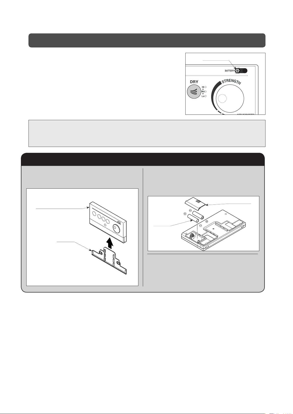
Replacing batteries in the remote control
As the batteries weaken, the battery lamp will begin to blink.
* Usually, this battery lamp turns off.
* The batteries provided with this product have been used to check
operations during construction, and so may have a useful life
shorter than commercially available batteries.
* Depending on the size of the room, the wall finish and color
(particularly dark colors), the remote control unit may stop
functioning before the battery lampstarts blinking.
Replace the batteries with new ones using the following procedure.
CAUTION: Correctly install the batteries with the positive (+) and negative (-) terminals
Battery lamp
facing the directions as shown on the remote control unit case.
Do not mix old and new batteries.
Only use alkaline batteries.
Replacing batteries in the remote control
1. Lift the remote control unit and
Remote remove it from its bracket.
2. Remove the back cover and replace
the batteries with new ones (four 1.5V
AA alkaline batteries).
Remote Control Unit
Bracket
Back Cover
Bracket
3. Replace the back cover, and set the
remote control unit back in its bracket.
38

Troubleshooting
You can easily correct some of the problems with this product. Before requesting repairs, please check
the following items.
If you are unable to correct the problem using the remedies shown below, contact the store where you
purchased this product.
All functions
Symptom
The system will not
operate at all.
Cause
Electricity is not being supplied to
the power outlet.
The power switch is off. The water
temperature and seat temperature
indicator lamps are off.
The power plug is not inserted into
the wall outlet.
Current is leaking.
Remote control’s light transmitter
or body’s light receiver is dirty.
The batteries in the remote control
are weak.
Remedy
Check for a power failure or tripped breaker,
etc.
Press the stop button for 2 seconds or longer
and get the water temperature and seat
temperature indicator lamps on the body to
light up. (See page 22.)
Insert the power plug securely into the wall
outlet.
Remove the power plug from the wall outlet,
let it sit for a while, and insert the plug in the
outlet again. If it still does not operate, pull
the power plug out and request repairs.
Remove the dirt.
Replace the batteries with new batteries. (See
page 38.)
Posterior cleaning and bidet cleaning
Symptom
Water does not spray
out.
The water shutoff valve is closed. Turn the water shutoff valve counterclockwise.
The strainer is clogged. Clean the strainer. (See page 31.)
Dirt or water drops are adhering to the
occupied seat sensor.
Tap water pressure is low. Spray
strength is set to “Lo”.
The occupied seat sensor is not
on.
Certain clothing is difficult for the
occupied seat sensor to detect
even if the seat is occupied.
The warm water tank is not full of
water.
Cause
Remedy
Remove the dirt or water drops from the
sensor. (See page 20.)
Set the spray strength to a higher level.
(See page 23.)
Sit back fully on the toilet seat, or change the
way you sit on the toilet. (See page 20.)
Place your hand close to the occupied seat
sensor. (See page 20.)
Carry out a trial operation. (See page 16.)
39

Posterior cleaning and bidet cleaning (continued)
Symptom
Spray water is not
warm.
Warm air drying
Symptom
Drying function does not
operate.
Dryer air is not warm.
Cause
Water temperature is not set to an
appropriate temperature.
The wash or bidet function was
used for a long period of time.
Power save is activated. Cancel power save. (See page 26.)
Cause
The occupied seat sensor is not
on.
Certain clothing is difficult for the
occupied seat sensor to detect
even if the seat is occupied.
Air temperature is not set to an
appropriate level.
Press the water temperature button
and adjust the water temperature to the
appropriate level. (See page 22.)
The water takes about 3 minutes to warm
back. (See page 20.)
Sit back fully on the toilet seat, or change the
way you sit on the toilet. (See page 20.)
Place your hand close to the occupied seat
sensor. (See page 20.)
Press the dry button and adjust the air
temperature to the appropriate level. (See
page 25.)
Remedy
Remedy
Warm air stops suddenly
before finishing.
The drying function has been used
for 4 minutes or longer.
Deodorizing
Symptom
The deodorizing fan
does not switch off.
Is any paper covering the seat
sensor?
Heated toilet seat
Symptom
Seat temperature is not set to an
The toilet seat is not
warm.
Toilet seat becomes
less warm when
seated long.
appropriate level.
Power save is activated. Cancel power save. (See page 26.)
The toilet seat heater auto off
function is operating.
Cause
Cause
Press the dry button again. (See page 25.)
Remedy
Please remove any paper blocking the seat
sensor.
Remedy
Press the seat temperature button and adjust
the seat temperature to the appropriate level.
(See page 22.)
Cancel the toilet seat temperature auto off
function. (See page 27.)
40

Others
Symptom
The body chatters and
deviates from correct
position.
The rear feet
(projections from the
rear) do not touch
the toilet (they are
floating).
The power lamp is
blinking.
Cause
The body is not locked.
There is trouble with the function
related with the blinking lamp.
There is trouble either with the
warm water or the toilet seat
functions.
Or it is time to check the shower
toilet.
Remedy
Push the body farther back and lock it in
position. (See page 34.)
It is not out of order.
The rear feet (projections from the rear)
were designed to float. Use the toilet as it
is.
It is broken. Pull the power plug from the
wall outlet and request repairs.
There is a malfunction or the maintenance
time. Unplug the power plug from the power
outlet, and call for repairs.
WARNING: A damaged or overheated power plug or cord, or a loose or overheated
wall outlet, could cause injury or damage the product. Under any of these
circumstances, remove the power plug from the wall outlet, contact us, and
discontinue using this product until the circumstances have been corrected.
WARNING: Do not allow anyone except an authorized service technician to disassemble,
repair, or modify this product. Doing so could result in electric hazard or fire, or
cause this product to malfunction and cause injury to users.
41
After-sales service
1. Before Requesting Repairs
If this product breaks down, see "Troubleshooting" on page 39. If the trouble is not repaired even after that,
contact the store where you purchased this product. Furthermore, even if there is no actual trouble, make
inquiry in the following cases.
If there are any points that are unclear even though the product is used in accordance with the
user's manual.
If the power cord is damaged or the outlet is loose.
The outlet or the power plug and power cord are overheating.
In the above cases, if it is left as it is without correction, there is danger of some unforeseen accident
occurring, so please get some advice.
WARNING
If the main unit, power plug, or power
cord are damaged (abnormal noise, odor,
smoke, high temperatures, cracking),
unplug the power plug from the power outlet
immediately, and have the part repaired.
* Failure to do so could cause electric shock or fire.
If water is leaking from the main unit or from the water
supply system, unplug the power plug from the power
outlet and close the water shutoff valve.
* Failure to do so could cause an electric shock or fire, or it
may cause the room to be flooded.
COMPULSORY
WARNING
Only authorized service
technicians are permitted to
disassemble, repair or modify
this product.
* There is a danger of electric
shock, fire, and injury.
DO NOT
DISASSEMBLE
2. Read the Warranty Certificate
This product comes with a Warranty Certificate. You will receive your Warranty Certificate once the
store where you purchased this product has completed the relevant information.
Check the details of the Warranty Certificate, and keep it in a secure place.
The warranty period is 2 years from the date of installation.
Even during the warranty period, there are some repairs for which you will be charged. Check the
details of your Warranty Certificate carefully.
3. Requesting repairs
Repairs within the warranty period
When requesting repairs, be sure to present
the Warranty Certificate. Repairs will be
performed in accordance with the provisions of
the warranty.
Details you will be asked
1. Address, Name, Telephone No.
2. Type, Product No., Color No., Serial No.
(See the Product No. label on the reverse side of the
toilet lid.)
3. Date of installation (See your Warranty Certificate.)
4. Description of malfunction or abnormal condition. (Be as
detailed as possible.)
5. Preferred date for house call
4.
If you want to know anything about the product or after-sales service
Consult the shop where you purchased this product.
42
Repairs after the warranty period has expired
If repairing the product will keep it functioning,
then, at your request, the repairs will be made
on a chargeable basis.
Charges for repairs include: Technical service
fee + Travel expenses + Parts costs.
Typ e
Product No.
Color No.
Serial No.

Specifications
Type CW-RS3-W
Water supply method Direct connection to tap water
Tap water pressure range 0.06 to 0.74 MPa (0.6 to 7.5 kgf/cm2)
Maximum rating AC 220 V, 305 W, 50 Hz
Product dimensions Width 426 mm x Depth 557.5 mm x Height 162 mm
Product weight Approx. 4.0 kg
Posterior and bidet cleaning
Warm water tank capacity Warm water storage 0.88 L
Nozzles Exclusive posterior, bidet nozzles, auto slide type
Nozzle holes
Posterior cleaning spray volume
Bidet cleaning spray volume 0 to 0.9 L/min. (adjustable in 5 stages)
Warm water heater capacity 250 W
Warm water internal control temperature
Safety devices Thermal fuses, High temperature sensor switch, Tank empty sensor circuit
Air volume 0.3 m3/min.
Drying
Air heater capacity 200 W
Air temperature adjustment Low (room temp.), Middle, High
Safety device Thermal fuses
Toilet seat
Heater capacity 45 W
Surface temperature
Temperature adjustment 4-steps selectable (micro-computer controlled)
Safety device Thermal fuse
Deodorization
Deodorizing method Chemisorption using a deodorizing cartridge
Deodorizing capacity 0.11 m3 / min.
Deodorizing cartridge life Approximately 7 years
Power save function One-touch power save (auto recovery after 8 hours)
Power cord Effective length: 1.0 m
Ambient operating temperatures 0 °C to 40 °C
Off (water temp.), Low (approx. 36 °C), Middle (approx. 38 °C), High (Approx. 40 °C)
Off (room temp.), Low (Approx. 28 °C), Middle (Approx. 36 °C), High (Approx. 40 °C)
* Occupied seat sensor
φ
1.3 mm x 2 holes, For bidet: φ0.9 mm x 10 holes.
0 to 0.9 L/min. (adjustable in 5 stages)
For posterior:
* Toilet seat lid one-touch removal
Other functions
* Body sliding removal mechanism
* Toilet seat heater auto off
* Toilet seat/toilet seat lid slow-down
* Adjustable side-lined toilet seat
mechanism
* Power switch
*
Included remote controller
* Posterior massage washing
CAUTION
This product is admitted to use only in your country. Do not use in any other countries.
43

Dealer (Store name, Address, Tel.)
GCW-1220A-W(11040)
Website: http://www.lixil.co.jp/
 Loading...