

InaVein Trivex User manual

InaVein TRIVEX®System
Operations/Service
Manual
Manufactured by
InaVein

InaVein TRIVEX®System Operations/Service Manual 1061421 Rev. F
1
GLOSSARY OF SYMBOLS
Manufacturer
On-Off Push Control
Mode Select Control
Speed Control
Up and Down Buttons
WARNING: HOT
Fluid bag
Lamp
Handpiece
Footswitch
Forward
Reverse
Oscillate
WINDOW LOCK
EU: Not for general waste
CE Mark
CAUTION: U.S. Federal law restricts this
device to sale by or on the order of a
physician.
On (Toggle Switch)
Off (Toggle Switch)
Non-ionizing electromagnetic radiation.
EQUIPMENT CLASSIFICATION—
Type BF applied part
DANGEROUS VOLTAGE: Danger of
Electric Shock
Alternating Current
Service Lifetime in Years
Catalog Number
Serial Number
Fuse
UL Classification
Keep Dry
Fragile; handle with care
This Way Up
European Representative

1061421 Rev. F InaVein TRIVEX
®
System Operations/Service Manual
2
TABLE OF CONTENTS
PREFACE
This manual contains information you need to operate and maintain the InaVein TRIVEX®System. It is
essential that you read and understand all the information in this manual before using or maintaining
the system.
TABLE OF CONTENTS
GLOSSARY OF SYMBOLS . . . . . . .1
PREFACE . . . . . . . . . . . . . . . . . . . . .2
DEVICE DESCRIPTION . . . . . . . . . .3
INDICATIONS FOR USE . . . . . . . . . .3
CONTRAINDICATIONS . . . . . . . . . . .3
WARNINGS . . . . . . . . . . . . . . . . . .4–5
PRECAUTIONS . . . . . . . . . . . . . . .5–6
SYSTEM COMPONENTS . . . . . .7–12
Resector Handpiece . . . . . . . . . . . .7
TRIVEX System Illuminator . . . . . .7
Component Identification . . . . . . . .7
Unpacking the Components . . . . . .8
Assembling the Components . . . . .8
Assemble Control Unit to Stand .8
Assemble Handle to Mast . . . . . .8
Control Unit Front Panel . . . . . .9–11
Front Panel Connectors . . . . . . .9
Console Controls
and Functions . . . . . . . . . . .10–11
Control Unit Rear Panel . . . . . . . .12
Power Switch . . . . . . . . . . . . . .12
Fuse Panel . . . . . . . . . . . . . . . .12
PREOPERATIVE SETUP . . . . .13–16
Setup . . . . . . . . . . . . . . . . . . . . . .13
Power Up . . . . . . . . . . . . . . . . .13
Tumescent Supply Setup . . . . .13
Resector Handpiece Saline
Supply Setup . . . . . . . . . . . . . . .14
Connecting the TRIVEX
Resector Handpiece
and Resector . . . . . . . . . . . . . . .15
Connecting the TRIVEX
System Illuminator . . . . . . . . . .16
OPERATIONS . . . . . . . . . . . . . .17–19
Resector Control . . . . . . . . . . . .17
Resector Handpiece
Suction Control . . . . . . . . . . . . .18
Resector Handpiece Irrigation
Control . . . . . . . . . . . . . . . . . . .18
Resector Speed . . . . . . . . . . . .19
Cutting . . . . . . . . . . . . . . . . . . . .19
Window Lock . . . . . . . . . . . . . . .19
Illuminator Irrigation . . . . . . . . .19
Illuminator Control . . . . . . . . . . .19
CLEANING AND STERILIZATION . . . . . .20
Resector Handpiece . . . . . . . . . . .20
Control Unit and Footswitches . . .20
Fiber Optic Cable . . . . . . . . . . . . .20
Illuminator . . . . . . . . . . . . . . . . . . .20
MAINTENANCE . . . . . . . . . . . . .21–23
Electrical Interference . . . . . . . . . . .21
Environmental Protection . . . . . . . . .21
Preventative Maintenance . . . . . . . .21
Hi-Pot Current Leakage Test . . . . . .21
Electrical Safety Checks . . . . . . . . .21
Dielectric Strength Test . . . . . . . . .22
Ground Test . . . . . . . . . . . . . . . . .22
Leakage Current Test
115 VAC with Power On . . . . . . . .23
Leakage Current Test
230 VAC with Power On . . . . . . . .23
SERVICE . . . . . . . . . . . . . . . . . .24–25
Service Philosophy . . . . . . . . . . . .24
Replacing the Lamp and Lamp
Life Indicator . . . . . . . . . . . . . . . . .24
TRIVEX System Fuses . . . .24–25
Resector Handpiece Cable . . . . . .25
Replacing the Handpiece
Cable . . . . . . . . . . . . . . . . . . . . .25
Returning the TRIVEX System
Control Unit . . . . . . . . . . . . . . . . . .25
TROUBLESHOOTING . . . . . . . .26–27
TECHNICAL SPECIFICATIONS . . .28
ORDERING INFORMATION . . . . . .29
GUIDANCE AND
MANUFACTURER’S DECLARATION ELECTROMAGNETIC
EMISSIONS . . . . . . . . . . . . . . . . . . .30
GUIDANCE AND
MANUFACTURER’S DECLARATION ELECTROMAGNETIC
IMMUNITY . . . . . . . . . . . . . . . . .31–32
GUIDANCE FOR SEPARATION
DISTANCES . . . . . . . . . . . . . . . . . . .33
WARRANTIES . . . . . . .BACK COVER
SERVICE REPLACEMENT
PROGRAM . . . . . . . . .BACK COVER
REPAIR SERVICE
PROGRAM . . . . . . . . .BACK COVER
FIGURES
1 Component Identification . . . . . . .7
2 Assemble control unit to stand . . .8
3 Control Unit Front Panel . . . . . . . .9
4 Control Unit Console . . . . . . . . .10
5 Control Unit Rear Panel . . . . . . .12
6 Tubing Connections . . . . . . . . . .14
7 Fiber Optic Cable Inspection . . .16
8 Resector Handpiece Controls . . .17
9 Fully Opened Resector
Handpiece Suction Lever . . . . . .18
10 Fully Closed Resector
Handpiece Suction Lever . . . . . .18
11 Lamp and Lamp Life Indicator . .24
TABLES
1 115 VAC 60 Hz
Leakage Current Test . . . . . . . . .23
2 230 VAC 50/60 Hz
Leakage Current Test . . . . . . . . .23

InaVein TRIVEX®System Operations/Service Manual 1061421 Rev. F
3
DEVICE DESCRIPTION
The TRIVEX®System uses a metal halide
arc lamp to provide intense, white light via
the TRIVEX System Illuminator for
transillumination. The illuminator connects
with fiber optic cables to the TRIVEX System
to provide transillumination during endoscopic
resection of superficial varicosities of the lower
extremities.
The TRIVEX System uses a pair of peristaltic
pumps to provide irrigation and tumescent
anesthesia for the Transilluminated Powered
Phlebectomy procedure. The left hand pump is
dedicated to providing the tumescent anesthesia
via the TRIVEX System Illuminator. The right
hand pump is dedicated to providing saline to
the TRIVEX Resector Handpiece
for resector tip irrigation.
INDICATIONS FOR USE
The TRIVEX System is indicated for use in
ambulatory phlebectomy procedures for the
resection and ablation of varicose veins.
CONTRAINDICATIONS
Use of the TRIVEX System is contraindicated in
situations where ambulatory phlebectomy is
contraindicated.
DEVICE DESCRIPTION/INDICATIONS FOR USE/CONTRAINDICATIONS

1061421 Rev. F InaVein TRIVEX
®
System Operations/Service Manual
4
Please read this manual before using the TRIVEX
®
System. The brief operating instructions in this
guide will make the system easier to use, while the
recommended service and maintenance procedures
will ensure optimal performance for years of reliable
use. As with any surgical instrument, there are
important health and safety considerations. These
are listed below and reiterated within the text.
Prior to using the TRIVEX System, it is essential
that all components of the system be inspected for
damage that can negatively impact the equipment
performance. The inspection should include all
equipment to be used in surgery, including the
illuminator, cables, and accessories.
When removing the TRIVEX System and accessories
from the shipping container, inspect contents to
ensure that all components from the “Unpacking
the Components” section are available.
Contact your authorized InaVein Representative if
damage is noted.
WARNINGS
• Before using the TRIVEX System for the first
time, you should review all available product
information. Surgeons should become familiar
with this surgical technique and the TRIVEX
System. Refer to the TRIVEX Surgical
Technique Guide (REF 1030501). You should
be experienced in ambulatory phlebectomy
surgery using powered instruments. Healthy
tissue can be injured by improper use of the
TRIVEX System resector. Use every available
means to avoid such injury.
• TRIVEX Resector Kits are packaged as a set.
They must be used as supplied. Do not
interchange resector components.
• Tube sets are provided STERILE and are for
single use only. Do not reuse. Do not resterilize.
Prior to use, inspect the product package for
signs of damage or tampering. Discard any
opened and unused product. Do not use after
the expiration date.
• The TRIVEX System pumps should not be
running while setting up the tubing. Injuries
to the operator’s hands can occur.
• Periodic irrigation of the tip of the resector is
recommended to provide adequate cooling of
the resector and to prevent accumulation of
excised materials in the surgical site. Ensure
that suction of 128 mmHg minimum is
maintained while the instrument is running.
• Work exclusively with sterile substances, sterile
fluids, and sterile accessories.
• This system is intended only for use with
flexible fluid containers and fluid bags. Glass
containers or bottles may break, and there is a
risk of implosion.
• Use of bags or containers not approved for this
system, or large and/or lopsided loads, may
cause the device to tip over.
• If visualization is lost during any point in the
procedure stop cutting immediately.
• Excessive pressure of the TRIVEX resector
against the vessel or prolonged activation of
the TRIVEX resector in a stationary position
may result in perforation of the resector
through the limb surface.
• Do not hold the light source shutter open
without a fiber optic cable in place. Failure to
observe this precaution may result in eye injury.
• During procedure, avoid prolonged contact of
the Illuminator tip to patient tissue or flammable
materials. The Illuminator tip may reach high
temperatures due to high-intensity light
transmission.
• DANGER: Risk of explosion if used in the
presence of flammable anesthetics.
• When the light source is turned on, do not look
directly at the metal halide arc lamp without
protective goggles.
• To prevent electrical shock, do not remove
the TRIVEX System console cover. There
are no user-serviceable components inside.
Dismantling the equipment will void the
warranty. Refer servicing to an authorized
InaVein representative.
• To prevent electrical shock, connect the power
cord to a properly-wired grounding receptacle
only.
• To prevent electrical shock, unplug the unit
from the electrical outlet before attempting to
replace the fuses.
• Use extreme caution: The high internal
pressure of the lamp may cause an explosion,
regardless of whether the lamp is cold or hot.
Always wear protective clothing and a face
mask when handling the lamp.
• Hazardous high voltage and energy are present
at the output and in the internal circuitry of this
unit.
• If this unit is configured as part of a system, the
entire system should be tested for compliance
with IEC 60601-1-1.
WARNINGS

InaVein TRIVEX®System Operations/Service Manual 1061421 Rev. F
5
• If the leakage current of the configured system
exceeds the limits of IEC 60601-1-1, install an
appropriately rated UL 60601-1/IEC 60601-1
approved isolation transformer and retest the
system.
• In some cases, high voltage may persist after
the power has been removed. Only personnel
qualified to service electronic equipment should
operate or troubleshoot an “uncased” power
supply.
• Dangerous voltages are present during leakage
current testing. DO NOT TOUCH the TRIVEX
System while power is applied.
• HIGH VOLTAGE (1500 VAC) is present during
dielectric strength and Hi-Pot testing. Exercise
extreme caution while operating the dielectric
strength tester or the Hi-Pot tester to prevent
personal injury from electrical shock or damage
to the equipment. Ensure that only authorized
personnel are in the test area during the tests.
• To avoid fire hazard, use only fuses of the
correct type, voltage rating, and current rating.
• The use of accessory equipment not complying
with the equivalent safety requirements of this
equipment may lead to a reduced level of safety
of the resulting system. Consideration relating
to the choice shall include:
– Use of the accessory in the patient vicinity.
– Evidence that the safety certification of the
accessory has been performed in accordance
to the appropriate IEC 60601-1 and/or
IEC 60601-1-1.
PRECAUTIONS
U.S. Federal law restricts this device to sale
by or on the order of a physician.
• Prior to use, examine the device(s) for possible
damage to assure proper functioning. If
damaged, do not use.
• Verify that the resector handpiece and its cable
are sterile.
• Verify that the illuminator and the fiber optic
cable are sterile.
• Check to ensure that the resector(s) required
for the procedure are available.
• Verify that the Preoperative Setup has been
successfully completed.
• Only InaVein Disposable TRIVEX Resector
Kits can be used with the TRIVEX System.
Resectors used with the TRIVEX System are for
single use only. Do not resterilize or lubricate
the resectors. Dispose of the resectors after
use.
• Use of reprocessed, single-use resectors may
permanently damage, impede performance, or
cause failure of your InaVein TRIVEX System.
Use of such products may render any
warranties null and void.
• Make sure the wheels on the TRIVEX System
roller base are locked to prevent the system
from rolling during setup and use.
• As in conventional ambulatory phlebectomy
procedures, bruising, hematoma, and
hemosiderin deposits have been observed in
clinical studies utilizing the TRIVEX System.
• Disconnect power cord before cleaning the
unit.
• Do not sterilize or immerse the TRIVEX System
console in disinfectant.
• To prevent moisture from entering the
handpiece cable during sterilization ensure that
the protective cap is screwed on completely.
Moisture can damage the cable or handpiece
connectors.
• Do not allow the rotating portion of any
resector to touch any metallic object such as
the illuminator. Damage to both instruments is
likely. Damage to the resector can range from
a slight distortion or dulling of the resector
edge to actual fracture of the tip in vivo. If
such contact does occur, inspect the tip. If
you find cracks, fractures or dulling, or if you
have any other reason to suspect a resector is
damaged, replace it immediately.
• Excessive leverage on the resector does not
improve cutting performance and, in extreme
cases, may result in wear and degradation of
the inner assembly.
• Do not cool the resector handpiece by
immersing it in cold water.
• Do not operate the resector in the open air for
an extended period, as the lack of irrigation
may cause the resector to overheat and seize.
WARNINGS
(Continued)
/ PRECAUTIONS

1061421 Rev. F InaVein TRIVEX
®
System Operations/Service Manual
6
• Use only the TRIVEX Light Source Adaptor
(REF 7210375) with this system. Use of any
other light source port adaptor may cause
reduced light emission from the fiber optic
cable.
• The power switch must be turned off, and the
power cord disconnected from the power
source, before attempting to replace the lamp.
• Replace the lamp and lamp life indicator only
with an appropriate InaVein lamp and lamp life
indicator (REF 7210115) as specified for the
TRIVEX System. Use of any other lamp or lamp
life indicator will void the warranty.
• Lamp may be very hot. Use protective eyewear
when handling lamp.
• Do not leave the operating light cord on a
patient or on patient drapes. Failure to observe
this precaution may result in burns to the
patient and/or to the surrounding drapes.
• This unit complies with IEC 60601-1-2.
However, the user must be aware that this does
not necessarily ensure protection of the unit
against interference from other devices.
• Do not operate at line voltage other than
those stipulated on the back of the unit.
• Ensure that the available mains voltage
matches the data listed on the label attached to
the back of the control unit. Incorrect voltage
can cause errors or malfunction, and may
destroy the equipment.
• Handle the unit with care. If the unit is dropped
or damaged in any way, it must be returned
immediately for service.
• Electrical safety testing should be performed
by a biomedical engineer or other qualified
person.
• This equipment contains electronic printed
circuit assemblies. At the end of the useful life
of the equipment it should be disposed of in
accordance with any applicable national or
institutional related policy relating to obsolete
electronic equipment.
• This equipment is designed and tested to
minimize interference with other electrical
equipment. However, if interference occurs
with other equipment it may be corrected by
one or more of the following measures:
– Reorient or relocate this equipment, the
other equipment, or both.
– Increase the separation between the pieces
of equipment.
– Connect the pieces of equipment into
different outlets or circuits.
– Consult a biomedical engineer.
• Equipment should be disposed of in
accordance with local and/or federal
codes and requirements.
PRECAUTIONS (Continued)
InaVein TRIVEX®System Operations/Service Manual 1061421 Rev. F
7
SYSTEM COMPONENTS
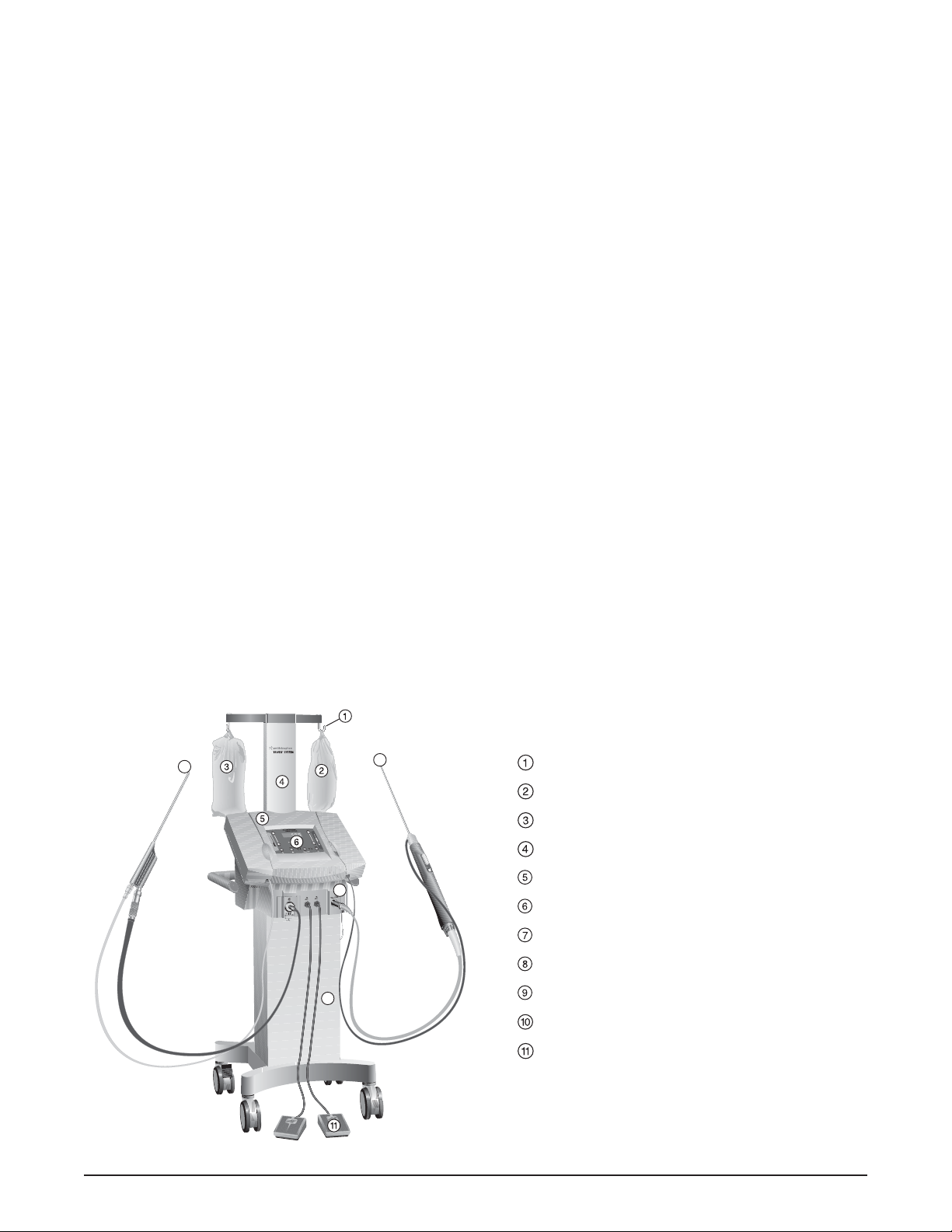
Figure 1. Component Identification
Fluid bag holder hooks (x2)
Saline solution bag
Tumescent solution bag
Irrigation mast
Control unit
Control unit console
Connection ports
TRIVEX System stand with Roller base
TRIVEX System Illuminator
TRIVEX System Resector
Footswitches (x2)
The TRIVEX®System consists of a variety of
components:
• The TRIVEX System control unit provides
controls for the mode and speed of the
TRIVEX Resector, for activation and flow of
the tumescent and saline pumps, and for
operation of the light source for the TRIVEX
System Illuminator.
The console includes a display for resector
speed and LED indicators for pump flow rate.
The four control buttons (tumescent pump,
lamp, resector mode, and saline pump) have
lighted indicators above and below each
push button. These indicate the status of
each component by illuminating steady
green, flashing green, steady orange, or
flashing orange.
• The front of the control unit has ports for
connecting the illuminator, two footswitches,
and resector.
• The TRIVEX System stand provides a mobile
base for the TRIVEX System control unit and
an irrigation mast for the saline and
tumescent solution irrigation bags.
• The 60 watt metal halide arc lamp provides
intense, white light via the TRIVEX System
Illuminator.
• The TRIVEX Resector Handpiece drives
the InaVein 4.5 mm TRIVEX Resector
(REF 7209514) and 5.5 mm TRIVEX
Resector (REF 7209515), and features
push-button controls for resector operation.
RESECTOR HANDPIECE
The TRIVEX Resector Handpiece is a hand-held
motor drive that is electrically connected to the
control unit via a 10 foot (3 meter) cable. The
resector handpiece drives the disposable
resectors.
The resector handpiece and its cable are
autoclavable (see “CLEANING AND
STERILIZATION”). The resector handpiece
cable is user replaceable (see “SERVICE”).
TRIVEX SYSTEM ILLUMINATOR
The TRIVEX System Illuminator (REF 7210351)
is an accessory, and is used to instill tumescent
solution and to transilluminate the targeted
varicosities. Please see the TRIVEX System
Illuminator Instructions for Use (REF 1061419)
for additional information.
Component Identification
0
9
8
1
7
1061421 Rev. F InaVein TRIVEX
®
System Operations/Service Manual
8
SYSTEM COMPONENTS (continued)
ASSEMBLING THE COMPONENTS
ASSEMBLE CONTROL UNIT TO STAND
1. Place the stand with roller base on a smooth
level surface with the rear panel facing you.
2. Remove the 3/16" Allen wrench from the base
of the irrigation mast. Using the Allen wrench,
remove the four bolts securing the rear panel
to the roller base.
3. Align the base of the control unit with the top
of the roller base and lower the control unit
straight down onto the roller base (figure 2).
4. For each of the four drawer latches located in
the interior of the roller base: lift and engage the
latch, then turn the latch key one half turn
clockwise. Fold the latch key flat.
5. Replace the rear panel and reinsert the four
bolts.
ASSEMBLE HANDLE TO MAST
6. Remove the four irrigation mast mounting bolts
from the rear of the control unit.
7. Assemble the handle to the mast by: removing
the two 1/4-20 x 5/8" socket head screws and
washers from the handle using the 3/16" Allen
wrench and then place the handle inside the
box section of the mast weldment. Orient the
handle so the threaded inserts align with the
hole openings in the box section of the
weldment. Secure the handle with the two,
1/4-20 x 5/8" socket head screws and washers.
8. Fit the irrigation mast with handle onto the rear
of the control unit and secure it with the four
irrigation mast mounting bolts.
Caution: Make sure the wheels on the TRIVEX
System roller base are locked to prevent the
system from rolling during setup and use.
UNPACKING THE COMPONENTS
Carefully unpack and inspect all components shipped with your InaVein TRIVEX System. If any parts
are missing or damaged, contact your authorized InaVein representative. Save the carton and packing
materials in the event a component must be returned for repair. You should have received the following:
Carton 1 of 2
1 ea. TRIVEX System Stand with Roller Base
1 ea. Irrigation Mast includes a 3/16" Allen wrench
attached at the base of the irrigation mast
1 ea. Irrigation Mast Handle
Carton 2 of 2
1 ea. REF 7210386 TRIVEX System Control Unit
1 ea. REF 1061421 Operations/Service Manual
2 ea. REF 7209791 TRIVEX System Footswitch
1 ea. REF 8005600 U.S. Power Cord
1 ea. REF 8013378 U.K. Power Cord
1 ea. REF 8013380 International Power Cord
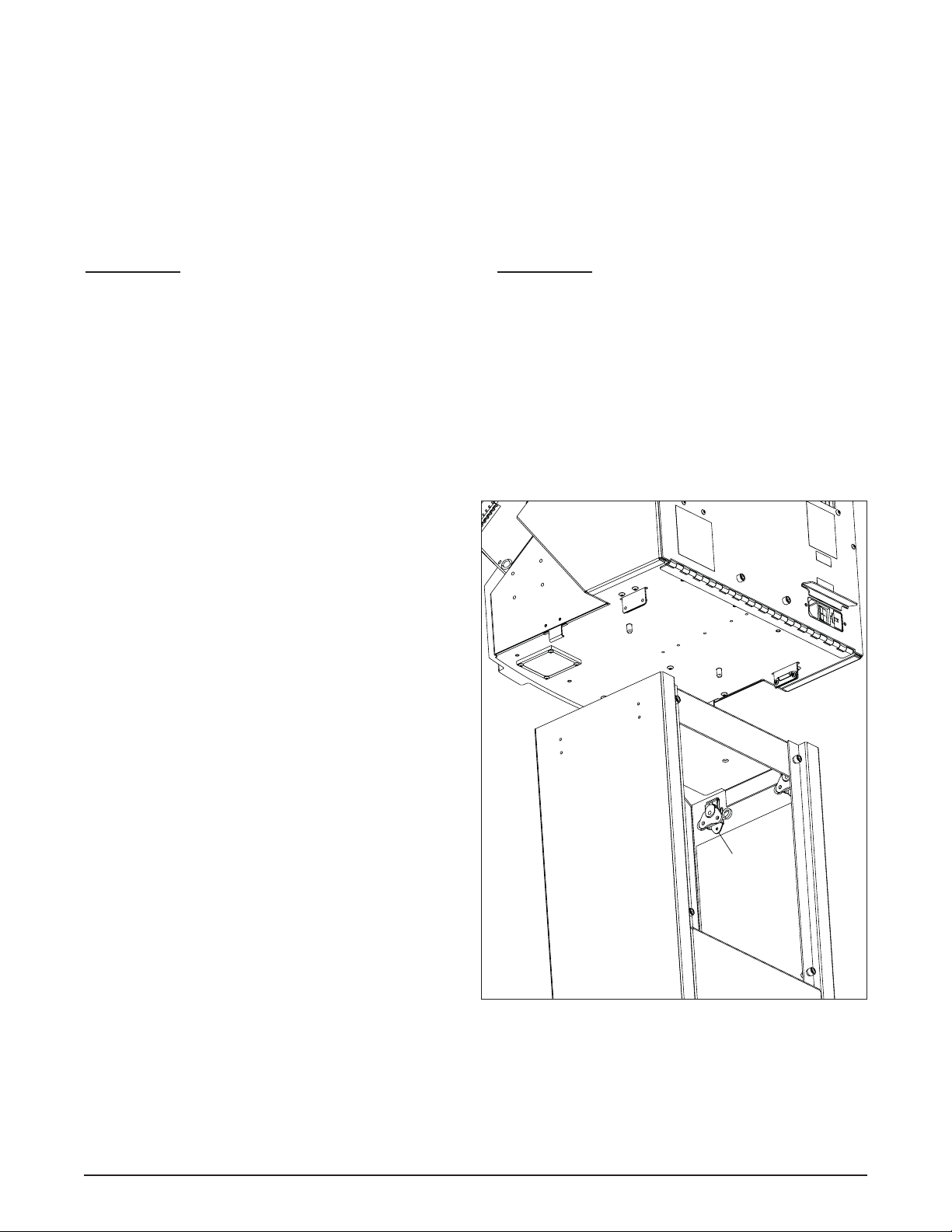
Figure 2. Assemble control unit to stand
Drawer latch
with key

InaVein TRIVEX®System Operations/Service Manual 1061421 Rev. F
9
SYSTEM COMPONENTS (continued)
TRIVEX®SYSTEM CONTROL UNIT FRONT PANEL
Figure 3. TRIVEX®System control unit front panel
CONTROL UNIT FRONT PANEL
1. Tumescent Pump Door – covers the
tumescent pump hardware.
2. Saline Pump Door – covers the saline pump
hardware.
3. TRIVEX System Console – contains the
push buttons and displays for system
operation.
FRONT PANEL CONNECTORS
There are four connectors on the front panel:
4. Fiber Optic Cable Connection Port –
self-closing port designed to accept the
TRIVEX Light Source Adaptor (REF
7210375).
Caution: Use of any other light source port
adaptor may cause reduced light emission
from the fiber optic cable.
5. Footswitch Tubing Connection Ports –
accept tubing for the TRIVEX System
footswitches.
6. Resector Handpiece Cable Connection Port
– accepts the Resector Handpiece cable.
3
1
4
5
6
2
1061421 Rev. F InaVein TRIVEX
®
System Operations/Service Manual
10
SYSTEM COMPONENTS (continued)
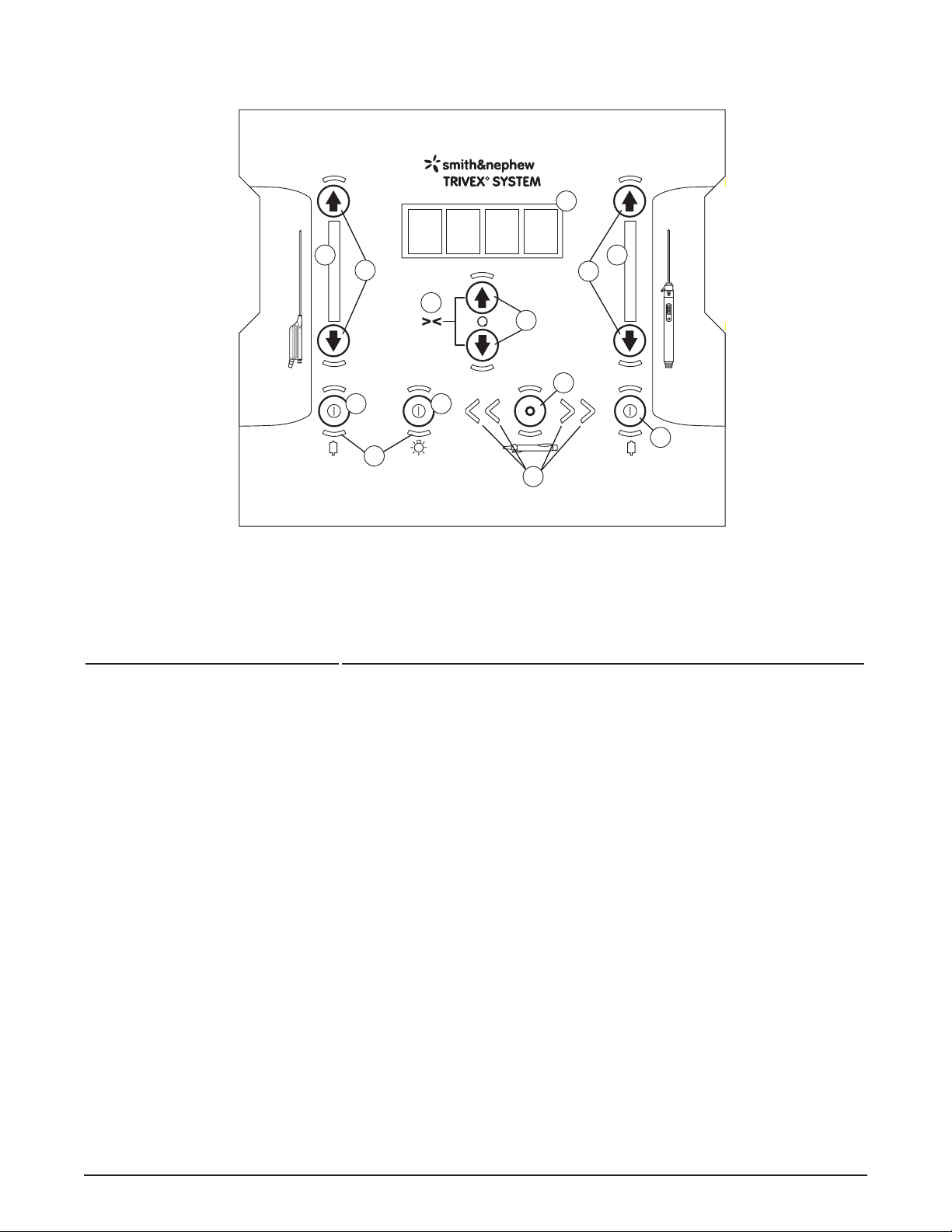
CONTROL FUNCTION
7. Tumescent Pump
ON/OFF Button
Turns the tumescent pump ON or OFF.
8. Tumescent Pump
Flow LED Indicators
Indicates the flow rate setting of the tumescent solution.
9. Tumescent Pump Flow
Increase / Decrease
Buttons
Increase or decrease the flow rate of the Tumescent pump. Each
press of a button results in the flow rate increasing or decreasing by
one level.
10. Lamp ON / OFF Button Turns the lamp ON or OFF.
11. Window Lock Control Holding down both Resector Speed Control increase/decrease
buttons simultaneously engages the Window Lock function.
12. Resector Speed Increase/
Decrease Buttons
Increase or decrease resector speed by 100 rpm with each button
press.
13. Resector Speed
Display (rpm)
Displays the current speed of the resector incrementally in 100 rpm
steps over a range of 100 rpm to 1500 rpm.
Figure 4. TRIVEX®System control unit console
CONSOLE CONTROLS AND FUNCTIONS
13
8
9
11
7
19
10
16
17
12
14
18
15
 Loading...