

Instruction Manual
PSG 10N/15N/ 25N
MSG 6/10/15 /25
STORAGE
WATER HEATER

1
Dear Customer,
Congratulations on the purchase of your INALSA Storage Water Heater !
This has been designed to include many superior features. You are now on the
threshold of a whole new world.
At INALSA, we have a reputation of manufacturing innovative, high quality
appliances such as Food Processors, Mixer Grinders, Juicer Mixer Grinders,
Cooking Ranges, Juice Extractors, Cooktops, Microwave Ovens, Oven
Toaster Grillers, Hand Blenders, Electric Kettles, Rice Cookers, and Electric
Chimneys. Your newly acquired INALSA Storage Water Heater bears the
same distinctive hallmark of excellence.
It is all the result of vigorous quality consciousness in INALSA's design and
development where uncompromising standards are maintained and rigid
quality control measures are exercised on raw materials, components and
finally, the finished product.
Your INALSA Storage Water Heater has a lot of thoughtful features built in
to make your working convenient. Please read these instructions carefully, so
that you may get the best out of the power packed features in your INALSA
Storage Water Heater.
Welcome to the INALSA world of living pleasure!
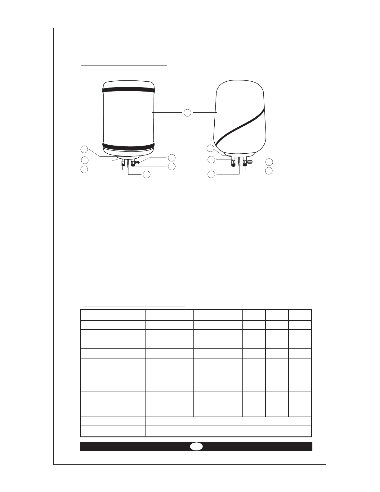
Parts Identification
Part No. Parts Name
1. Outer casing
2. Inspection cover
3. Water inlet (Blue)
4. Water outlet (Red)
5. Drain pipe
6. Indicator lamps
7. Pressure relief valve (PRV)
Technical Specifications*
Model No. PSG10N PSG 15N PSG 25N MSG6 MSG10 MSG 15 MSG 25
Capacity (in lt.) 10 15 25 6 10 15 25
Wattage (in kW) 2.0 2.0 2.0 2.0 2.0 2.0 2.0
Star rating NA 5 Star 5 Star NA NA 5 Star 5 Star
Max. pressure rating (psi) 90 100 100 90 90 100 100
Normal working pressure 30 30 30 30 30 30 30
rating (psi)
Minimum hot water 40 40 40 40 40 40 40
output temperature (C)
Max. mixing factor (%) 35 40 40 35 35 40 40
Max. Reheating time for
50°C temperature (in min.) 55 70 90 45 55 70 90
Outer casing Plastic MS Power coated
Power supply 230V, 50Hz, AC, Single Phase
2
Metal casing Plastic casing
1
2
4
5
3
7
6
4
3
7
5
2

3
Indicator Red:- Heating
Green:- Cut-out
Water tank Stainless Steel
Heating element - Two U, embedded type, copper sheathed, tubular
with mineral filling. (All models except MSG 6).
- Single element, embedded type, copper sheathed,
tubular with mineral filling ( Model MSG 6).
Thermostat Stem-type Pre-set at 60°C
Thermal cutout Stem type, Reset type to operate at 90°C
Fusible plug Operate at 98°C
* Due to continuous improvements in product, specifications are subject to
change without prior notice.
Features
1. Reset type automatic thermal cut-out for safety
2. Pressure relief valve for high pressure built-up
3. Siphon hole for low water pressure
4. Fusible plug for total safety
5. High grade stainless steel tank
6. Thermostatically controlled
7. Drain pipe to drain out the water when the heater is not in usage
8. Two U heating element. (All models except MSG 6)
9. Nonagonal tank protection.
Important Instructions
Please read operating instructions before using the appliance to ensure
safe and reliable performance.
Do's
1. Before plugging in the socket ensure that the mains voltage complies
with the rated one.
2. Qualified service personnel shall do periodic drainage of water from the
heater. This reduces the chances of scaling of heating element and tank.
3. Switch Off the power supply and drain out the remaining water in the
tank. This prevents scaling of both element and tank.
4. The gate valve at the inlet shall be kept open.
5. Servicing should be done at least once a year.
6. Make sure that no other appliance(s) is (are) plugged into the same
circuit with heater, as this may overload the circuit.

4
7. If the main cord of the heater is damaged, authorized service personnel
must only replace it.
Don'ts
1. Do not switch ON the heater till it is completely filled with water.
2. Do not install a pressure reducer valve at the inlet.
3. Safety devices are pre-set and are sensitive. Do not temper with them.
This could be hazardous.
5. Do not use outdoors. This product is for household use only.
6. In case of any abnormality during operation, immediately switch OFF
the main power supply and contact the nearest service center.
How to Install
1. Installation should be done by a qualified plumber / electrician.
2. There should be enough space around the heater for easy installation and
servicing.
3. Make sure that the supporting walls or fixtures are strong enough to
carry the weight of the heater when it is completely filled with water.
4. Fix the water heater in perfectly straight position at a suitable height
from the floor.
5. There should be a minimum space of 50 cm between the heater unit and
roof. This is to ensure that heater can be removed easily when required.
6. The heater should be saved from being damaged by splashing water. For
this keep a minimum distance of 1.8 M between the floor and bottom of
the heater.
7. During installation and plumbing (generally by flexible metal pipes)
connect the plumbing by bending the flexible pipes or elbow.
Installation Positions
Mounting Dimensions (in mm)
Model A B C D Approx. Weight Pipe connection
of water Heater (in mm)
with Water (in kg)
PSG10N 175 185 475 310 15.0 12mm (½")
PSG15N 228 215 550 365 24.0 12 mm (½")
PSG25N 235 250 605 435 36.0 12 mm (½")
MSG 6 160 200 400 265 11.0 12 mm (½")
MSG10 270 195 490 270 17.0 12mm (½")
MSG15 222 307 505 340 25.0 12 mm (½")
MSG25 288 307 640 370 37.0 12 mm (½")

5
Mounting diagram
Water supply
1. You can connect the water heater directly to the overhead water supply
tank. Do not connect the water heater directly to water lifting pumps.
2. The water should not be too low. The minimum height between the
heater and water supply should be at least 2M.
Water connections
1. Do not connect the cold and hot water pipelines directly to the heater.
Instead connect them using flexible copper pipes. Never use plastic
tubes especially at the outlet, as it cannot withstand heat over extended
usage. In case of direct pipe connections, tightening of couplings using
wrench can damage the heater unit. Always use control / gate valves at
the inlet and outlet. Ensure that the valve at the inlet is always open.
Electrical wiring
Make sure that connections in the plug & socket are secure and proper
earthing is provided to the unit.
A
C
D
B
Wiring diagram

6
How to Use
1. Do not switch ON the power supply before filling the heater with water.
2. Leave the hot water outlet open and open the inlet valve to allow the
heater unit to be filled with water. When the heater is full the water will
start flowing out from the outlet.
3. Now close the gate valve at the outlet. Always keep the inlet valve open.
4. Switch ON the power supply. Red neon lamps will glow 'ON' to indicate
that water is getting heated.
5. When the water is heated to the pre-fixed temperature, red lamp will get
OFF. This indicates that the thermostat has operated. You can now take
the hot water out through the outlet.
6. It is advisable to switch OFF the power supply when the unit is not in
use.
Note: In case green light glow ON, this indicates that thermostat has failed
and needs to be replaced.
Safety Devices
Thermostat
An adjustable ISI marked bimetallic stem type snap action thermostat
with temperature range between 25 C to 75 C, generally set at 60 C
cuts the electric power supply as soon as the water temperature rises
above the set temperature and restarts automatically when the
temperature goes low.
Reset type thermal cutout
It is bimetallic type snap action devices set to operate at 90 C. In
abnormal conditions, if the water temperature inside the tank exceeds
90 C or if the water heater is switched on with water the thermal cut the
power supply and protects the system.
Fusible Plug
Accidentally if the thermostat and the thermal cutout fails to operate, the
fusible plug melts at around 98 C reducing the water steam pressure
inside the tank.
Pressure relief valve
2
The PRV is set at 3.5 Kg/cm (50PSI). It prevents the pressure built up
inside the tank by bleeding out the water through the PRV when the
2
incoming pressure exceeds the set pressure of 3.5 Kg/cm

Non- Return Device
There is a siphon hole on the inlet pipe inside the inner tank of water
heater. At low pressure, the siphon prevents back flow of the water. It
acts as a non-return device upto a certain level of low pressure and
prevents vacuum formation that can lead to tank collapse and thus
leakage.
Cleaning and maintenance
Routine Inspection/Maintenance Chart
S.No. Inspection item Frequency Remarks
1. Pressure relief Every 3 If the water quality is
valve (PRV) months/1 yr. bad because of
of seasonal use hardness & suspended
impurities .
2. Fusible plug Every 3
months/1 yr.
of seasonal use
3. Heating element 18 months/6 yrs. In case of bad water
of seasonal use quality, inspect after
every 6 months of
continuous use or
every 2 yrs. of
seasonal use.
7
 Loading...