

Inalp Networks SmartWare Release 2.10 Software Configuration Manual

Software
Configuration
Guide
SmartWare Release 2.10
Customer Deliverable Documentation
Part Number 80-0151
English
Revision 1.00, October 31, 2002

2 Legal Notice
Software Configuration Guide Release 2.10, Revision 1.00

Legal Notice 3
LEGAL NOTICE
Copyright ©2002 Inalp Networks AG
All rights reserved. No part of this publication may be reproduced without prior written permission
from Inalp Networks AG.
Inalp Networks AG reserves the right to make changes in specifications and other information
contained in this document without prior notice. The information provided is subject to change
without notice.
In no event shall Inalp Networks AG or its employees and associated companies be liable for any
incidental, special, indirect or consequential damages whatsoever, including but not limited to lost
profits, arising out of or related to this manual or the information contained within it, even if Inalp
Networks AG has been advised of, known, or should have known, the possibility of such damages.
Inalp, the Inalp logo, and SmartNode are registered trademarks of Inalp Networks AG. SmartWare
and SmartView Management Center are trademarks of Inalp Networks AG. All other trademarks
mentioned in this document are property of their respective owners.
EU Declaration of Conformity
The EU Directives covered by this Declaration
99/5/EC Guideline of the European Parliament and the Committee for the Harmonization of the
Legal Regulations of the Member States concerning radio equipment and
telecommunications terminal equipment and the mutual recognition of their conformity.
The Products covered by this Declaration
The products covered by this declaration are the SmartNode 1000 and 2000 family series devices.
The Basis on which Conformity is being Declared
The products identified above comply with the requirements of the above EU directives by meeting
the following standards:
• Safety Compliance: EN 60950 (Edition 1997)
• EMC Compliance: EN 55022 (Edition 1998), EN 55024 (Edition 1998)
• ISDN Terminal Equipment Requirements (BRI): ETS TBR3 (Edition 1999)
• ISDN Terminal Equipment Requirements (PRI): ETS TBR4 (Edition 1999)
The CE mark was first applied in 2000.
Inalp Networks AG
Meriedweg 7
CH-3172 Niederwangen
Software Configuration Guide Release 2.10, Revision 1.00

4 Table of Contents
TABLE OF CONTENTS
1 Terms and Definitions................................................................................................16
1.1 Introduction.......................................................................................................................................16
1.2 SmartWare Architecture Terms and Definitions..........................................................................16
2 Applications..................................................................................................................23
2.1 Introduction.......................................................................................................................................23
2.2 Carrier Networks..............................................................................................................................23
2.3 Enterprise Networks ........................................................................................................................24
2.4 LAN Telephony ................................................................................................................................25
3 System Overview ......................................................................................................... 27
3.1 Introduction.......................................................................................................................................27
3.2 SmartNode Hardware Platforms....................................................................................................28
3.3 SmartWare Embedded Software ....................................................................................................29
3.4 SmartView Management Center Tools..........................................................................................30
4 Configuration Concepts..............................................................................................31
4.1 Introduction and Overview.............................................................................................................31
4.2 Contexts and Gateways ...................................................................................................................32
4.2.1 Context .......................................................................................................................................32
4.2.2 Gateway .....................................................................................................................................32
4.3 Interfaces, Ports and Bindings ........................................................................................................32
4.3.1 Interfaces....................................................................................................................................32
4.3.2 Ports and Circuits .....................................................................................................................33
4.3.3 Bindings .....................................................................................................................................33
4.4 Profiles and Use commands............................................................................................................33
4.4.1 Profiles........................................................................................................................................33
4.4.2 Use Commands.........................................................................................................................34
5 Command Line Interface............................................................................................35
5.1 Command Modes .............................................................................................................................35
5.1.1 System Prompt..........................................................................................................................36
5.1.2 Navigating the CLI...................................................................................................................37
5.2 Command Editing ............................................................................................................................39
5.2.1 Command Help.........................................................................................................................39
5.2.2 The No Form .............................................................................................................................39
5.2.3 Command Completion ............................................................................................................39
5.2.4 Command History....................................................................................................................39
5.2.5 Command Editing Shortcuts...................................................................................................39
6 Accessing the Command Line Interface..................................................................41
6.1 Introduction.......................................................................................................................................41
6.2 Warning .............................................................................................................................................41
6.3 Accessing the SmartWare Command Line Interface Task List ..................................................41
6.4 Accessing via the Console Port....................................................................................................... 42
6.4.1 Console Port Procedure ...........................................................................................................42
6.5 Accessing via a Telnet Session........................................................................................................42
6.5.1 Telnet Procedure.......................................................................................................................43
6.6 Log On to SmartWare ......................................................................................................................44
6.6.1 Warning .....................................................................................................................................44
6.7 Selecting a Secure Password ...........................................................................................................44
6.8 Configure Operators and Administrators.....................................................................................45
6.9 Factory Preset Administrator Account..........................................................................................45
6.10 Create an Operator Account ...........................................................................................................45
6.11 Create an Administrator Account ..................................................................................................46
6.12 Displaying the CLI Version............................................................................................................. 46
Software Configuration Guide Release 2.10, Revision 1.00

Table of Contents 5
6.13 Display Account Information ......................................................................................................... 47
6.14 Switching to Another Account ....................................................................................................... 47
6.15 Checking Identity and Connected Users.......................................................................................48
6.16 End a Telnet or Console Port Session ............................................................................................49
7 Establishing Basic IP Connectivity...........................................................................50
7.1 Introduction ......................................................................................................................................50
7.2 IP Context Selection and Basic Interface Configuration Tasks...................................................50
7.3 Enter the IP Context, Create IP Interfaces and Assign an IP Address ...................................... 50
7.4 Define IP Ethernet Encapsulation and Bind IP Interface to Physical Port................................ 51
7.5 Activating a Physical Port............................................................................................................... 52
7.6 Display IP Interface Information.................................................................................................... 53
7.7 Delete IP Interfaces........................................................................................................................... 53
7.8 Examples............................................................................................................................................ 54
7.8.1 Setting Up an IP Interface on an Ethernet Port ....................................................................54
8 System Image Handling .............................................................................................56
8.1 Introduction ......................................................................................................................................56
8.2 Memory Regions in SmartWare.....................................................................................................56
8.3 Boot Procedure and Bootloader......................................................................................................58
8.4 Factory Configuration......................................................................................................................59
8.5 Warning ............................................................................................................................................. 59
8.6 System Image Handling Task List .................................................................................................59
8.7 Display System Image Information ............................................................................................... 59
8.8 Copy System Images from a Network Server to Flash Memory ...............................................60
8.9 Copy Driver Software from a Network Server to Flash Memory..............................................61
9 Configuration File Handling ..................................................................................... 63
9.1 Introduction ......................................................................................................................................63
9.1.1 Understanding Configuration Files.......................................................................................63
9.2 Factory Configuration......................................................................................................................65
9.3 Warnings ...........................................................................................................................................66
9.4 Configuration File Handling Task List..........................................................................................66
9.5 Copy Configurations within the Local Memory..........................................................................66
9.6 Replacing the Startup Configuration with a Configuration from Flash Memory...................68
9.7 Copy Configurations to and from a Remote Storage Location.................................................. 69
9.8 Replacing the Startup Configuration with a Configuration downloaded from TFTP Server70
9.9 Displaying Configuration File Information.................................................................................. 71
9.10 Modifying the Running Configuration at the CLI....................................................................... 71
9.11 Modifying the Running Configuration Offline............................................................................ 72
9.12 Deleting a Specified Configuration................................................................................................ 73
10 Basic System Management .....................................................................................75
10.1 Overview ........................................................................................................................................... 75
10.2 Basic System Management Configuration Task List...................................................................75
10.3 Setting System Information............................................................................................................. 75
10.4 Setting the System Banner............................................................................................................... 77
10.5 Setting Time and Date .....................................................................................................................78
10.6 Display Clock Information.............................................................................................................. 78
10.7 Display Time since last Restart....................................................................................................... 78
10.8 Configuring and Starting the Web Server.....................................................................................79
10.9 Determining and Defining the active CLI Version ...................................................................... 79
10.10 Restarting The System ................................................................................................................. 80
10.11 Displaying the System Logs........................................................................................................ 81
10.12 Controlling Command Execution .............................................................................................. 81
10.13 Displaying the Checksum of a Configuration..........................................................................83
11 IP Context Overview ................................................................................................84
11.1 Introduction ......................................................................................................................................84
11.2 IP Context Overview Configuration Task List.............................................................................85
Software Configuration Guide Release 2.10, Revision 1.00

6 Table of Contents
11.3 Planning your IP Configuration.....................................................................................................86
11.3.1 IP Interface Related Information ............................................................................................86
11.3.2 Serial Interface Related Information ......................................................................................86
11.3.3 QoS Related Information .........................................................................................................87
11.4 Configuring Ethernet and Serial Ports...........................................................................................87
11.5 Creating and Configuring IP Interfaces.........................................................................................87
11.6 Configuring NAPT...........................................................................................................................87
11.7 Configuring Static IP Routing.........................................................................................................88
11.8 Configuring RIP................................................................................................................................88
11.9 Configuring Access Control Lists...................................................................................................88
11.10 Configuring Quality of Service...................................................................................................89
12 IP Interface Configuration ......................................................................................90
12.1 Introduction.......................................................................................................................................90
12.2 Software Configuration Guide Release 2.10 Task List.................................................................90
12.3 Creating an IP Interface ...................................................................................................................90
12.4 Deleting an IP Interface....................................................................................................................91
12.5 Setting the IP Address and Netmask.............................................................................................92
12.6 ICMP Message Processing...............................................................................................................92
12.7 ICMP Redirect Messages .................................................................................................................93
12.8 Router Advertisement Broadcast Message ...................................................................................93
12.9 Defining the MTU of the Interface .................................................................................................94
12.10 Configuring an Interface as a Point-to-Point Link...................................................................95
12.11 Displaying IP Interface Information ..........................................................................................95
12.12 Testing Connections with the ping Command.........................................................................96
12.13 Traceroute......................................................................................................................................97
12.14 Examples........................................................................................................................................ 97
12.14.1 Deleting an IP Interface Example .......................................................................................97
13 NAPT Configuration................................................................................................98
13.1 Overview ...........................................................................................................................................98
13.2 Configuring Network Address Port Translation .........................................................................98
13.3 NAPT Configuration Task List.......................................................................................................98
13.4 Creating a NAPT Profile..................................................................................................................98
13.5 Adding a Static NAPT Entry...........................................................................................................99
13.6 Removing a Static NAPT Entry ....................................................................................................100
13.7 Configuring an ICMP Default Server ..........................................................................................100
13.8 Removing an ICMP Default Server..............................................................................................101
13.9 Configuring an NAPT Interface ...................................................................................................101
13.10 Display NAPT Configuration Information .............................................................................102
14 Ethernet Port Configuration .................................................................................103
14.1 Introduction.....................................................................................................................................103
14.2 Ethernet Port Configuration Task List.........................................................................................103
14.3 Entering the Ethernet Port Configuration Mode........................................................................103
14.4 Configuring Medium for an Ethernet Port .................................................................................104
14.5 Configuring Ethernet Encapsulation Type for an Ethernet Port..............................................105
14.6 Binding An Ethernet Port to an IP Interface ...............................................................................105
14.7 Selecting The Frame Format for an Ethernet Port......................................................................106
14.8 Configuring Layer 2 CoS to Service Class Mapping for an Ethernet Port..............................107
14.9 Adding a Receive Mapping Table Entry .....................................................................................107
14.10 Adding a Transmit Mapping Table Entry...............................................................................108
14.11 Closing an Ethernet Port............................................................................................................108
15 Link Scheduler Configuration .............................................................................110
15.1 Introduction.....................................................................................................................................110
15.2 Quick References ............................................................................................................................111
15.2.1 Setting the Modem Rate.........................................................................................................111
15.3 Command Cross Reference...........................................................................................................112
Software Configuration Guide Release 2.10, Revision 1.00

Table of Contents 7
15.4 Link Scheduler Configuration Task List .....................................................................................113
15.5 Defining the Access Control List Profile ..................................................................................... 113
15.5.1 Packet Classification...............................................................................................................113
15.5.2 Creating an Access Control List ........................................................................................... 114
15.6 Assigning Bandwidth to Traffic Classes ..................................................................................... 115
15.7 Creating a Top-Level Service Policy Profile ...............................................................................118
15.8 Specifying Source Classes or Lower Level Source Policy Profiles...........................................120
15.8.1 Defining Fair Queuing Weight ............................................................................................. 120
15.8.2 Defining the Bit-Rate.............................................................................................................. 121
15.8.3 Defining Absolute Priority....................................................................................................121
15.8.4 Defining the Maximum Queue Length ............................................................................... 121
15.8.5 Specifying the Type-Of-Service (TOS) Field.......................................................................122
15.8.6 Specifying the Precedence Field...........................................................................................122
15.8.7 Specifying Differentiated Services Codepoint Marking....................................................123
15.8.8 Specifying Layer 2 Marking..................................................................................................125
15.8.9 Defining Random Early Detection....................................................................................... 125
15.8.10 Discarding Excess Load.....................................................................................................126
15.9 Devoting the Service Policy Profile to an Interface....................................................................126
15.10 Displaying Link Arbitration Status.......................................................................................... 128
15.11 Displaying Link Scheduling Profile Information................................................................... 128
15.12 Enable Statistics Gathering........................................................................................................129
16 Serial Port Configuration ......................................................................................130
16.1 Introduction ....................................................................................................................................130
16.2 Serial Port Configuration Task List.............................................................................................. 130
16.3 Disabling an Interface .................................................................................................................... 131
16.4 Enabling an Interface ..................................................................................................................... 131
16.5 Configuring the Serial Encapsulation Type................................................................................ 132
16.6 Configuring the Hardware Port Protocol ...................................................................................133
16.7 Configuring the Active Clock Edge.............................................................................................134
16.8 Enter Frame Relay Mode............................................................................................................... 135
16.9 Configuring the LMI Type............................................................................................................ 135
16.10 Configuring the Keepalive Interval ......................................................................................... 136
16.11 Enabling Fragmentation............................................................................................................ 136
16.12 Entering Frame Relay PVC Configuration Mode .................................................................. 138
16.13 Configuring the PVC Encapsulation Type.............................................................................. 139
16.14 Binding the Frame Relay PVC to IP Interface.........................................................................139
16.15 Disabling a Frame Relay PVC................................................................................................... 140
16.16 Displaying Frame Relay Information ...................................................................................... 141
16.17 Examples...................................................................................................................................... 141
16.17.1 Displaying Serial Port Information..................................................................................141
16.17.2 Displaying Frame Relay Information .............................................................................. 142
16.17.3 Integrated Service Access..................................................................................................142
17 Basic IP Routing Configuration ...........................................................................146
17.1 Introduction ....................................................................................................................................146
17.2 Basic IP Routing Configuration Task List...................................................................................146
17.3 Configuring Static IP Routes......................................................................................................... 147
17.4 Deleting Static IP Routes ............................................................................................................... 147
17.5 Displaying IP Route Information.................................................................................................148
17.6 Examples.......................................................................................................................................... 149
17.6.1 Basic Static IP Routing Example........................................................................................... 149
18 RIP Configuration ..................................................................................................150
18.1 Introduction ....................................................................................................................................150
18.2 Routing Protocol............................................................................................................................. 150
18.3 RIP Configuration Task List..........................................................................................................151
18.4 Enabling Send RIP.......................................................................................................................... 151
Software Configuration Guide Release 2.10, Revision 1.00

8 Table of Contents
18.5 Enabling an Interface to Receive RIP ...........................................................................................152
18.6 Specifying the Send RIP Version..................................................................................................152
18.7 Specifying the Receive RIP Version .............................................................................................153
18.8 Enabling RIP Learning...................................................................................................................153
18.9 Enabling an Interface to Receive RIP ...........................................................................................154
18.10 Enabling RIP Announcing.........................................................................................................154
18.11 Enabling RIP Auto Summarization.......................................................................................... 155
18.12 Specifying The Default Route Metric....................................................................................... 155
18.13 Enabling RIP Split-Horizon Processing................................................................................... 156
18.14 Enabling The Poison Reverse Algorithm ................................................................................157
18.15 Enabling Holding Down Aged Routes....................................................................................157
18.16 Displaying RIP Configuration of an IP Interface....................................................................158
18.17 Displaying Global RIP Information .........................................................................................158
19 Access Control List Configuration ......................................................................160
19.1 About Access Control Lists ...........................................................................................................160
19.1.1 What Access Lists Do .............................................................................................................160
19.1.2 Why You Should Configure Access Lists............................................................................160
19.1.3 When to Configure Access Lists...........................................................................................161
19.1.4 Features of Access Control Lists...........................................................................................161
19.2 Software Configuration Guide Release 2.10 Task List...............................................................162
19.3 Map Out the Goals of the Access Control List............................................................................162
19.4 Create an Access Control List Profile and Enter Configuration Mode ...................................162
19.5 Add a Filter Rule to the Current Access Control List Profile...................................................163
19.6 Add an ICMP Filter Rule to the Current Access Control List Profile......................................164
19.7 Add a TCP, UDP or SCTP Filter Rule to the Current Access Control List Profile.................166
19.8 Bind and Unbind an Access Control List Profile to an IP Interface.........................................168
19.9 Display an Access Control List Profile ........................................................................................169
19.10 Debug an Access Control List Profile ......................................................................................169
19.11 Examples...................................................................................................................................... 171
19.11.1 Deny a Specific Subnet.......................................................................................................171
20 SNMP Configuration .............................................................................................172
20.1 Simple Network Management Protocol (SNMP).......................................................................172
20.1.1 Background..............................................................................................................................172
20.1.2 SNMP Basic Components......................................................................................................172
20.1.3 SNMP Basic Commands........................................................................................................173
20.1.4 SNMP Management Information Base (MIB).....................................................................173
20.1.5 Network Management Framework......................................................................................173
20.2 Identification of the SmartNode 1000 and 2000 Series via SNMP ...........................................174
20.3 Warnings..........................................................................................................................................174
20.4 SNMP Tools.....................................................................................................................................174
20.5 SNMP Configuration Task List.....................................................................................................174
20.6 Setting Basic System Information................................................................................................. 175
20.7 Setting Access Community Information ..................................................................................... 176
20.8 Setting Allowed Host Information............................................................................................... 178
20.9 Specifying The Default SNMP Trap Target ................................................................................178
20.10 Displaying SNMP Related Information...................................................................................179
20.11 Using the AdventNet SNMP Utilities......................................................................................180
20.11.1 Using the MibBrowser .......................................................................................................180
20.11.2 Using the TrapViewer........................................................................................................181
20.12 Standard SNMP Version 1 Traps..............................................................................................183
20.13 SNMP Interface Traps................................................................................................................184
21 SNTP Client Configuration ..................................................................................186
21.1 Introduction.....................................................................................................................................186
21.2 Software Configuration Guide Release 2.10 Task List...............................................................186
21.3 Selecting SNTP Time Servers........................................................................................................186
Software Configuration Guide Release 2.10, Revision 1.00

Table of Contents 9
21.4 Defining SNTP Client Operating Mode ...................................................................................... 187
21.5 Defining SNTP Local UDP Port....................................................................................................188
21.6 Enabling and Disabling the SNTP Client....................................................................................188
21.7 Defining SNTP Client Poll Interval..............................................................................................189
21.8 Defining SNTP Client Constant Offset To GMT........................................................................ 189
21.9 Defining the SNTP Client Anycast Address............................................................................... 190
21.10 Enabling and Disabling Local Clock Offset Compensation..................................................190
21.11 Enabling and Disabling Root Delay Compensation..............................................................191
21.12 Showing SNTP Client Related Information............................................................................ 192
21.13 Debugging SNTP Client Operation ......................................................................................... 192
21.14 Recommended Public SNTP Time Servers.............................................................................193
21.14.1 NIST Internet Time Service ............................................................................................... 193
21.14.2 Other Public NTP Primary (stratum 1) Time Servers.................................................... 194
21.14.3 Additional Information on NTP and a List of other NTP servers ...............................195
21.14.4 Recommended RFC............................................................................................................ 195
22 DHCP Configuration .............................................................................................196
22.1 Introduction to DHCP ...................................................................................................................196
22.2 DHCP-Client Configuration Tasks .............................................................................................. 197
22.3 Enable DHCP-Client on an IP interface.......................................................................................197
22.4 Release or Renew a DHCP Lease Manually (Advanced)..........................................................198
22.5 Get Debug Output from DHCP-Client........................................................................................ 199
22.6 DHCP-Server Configuration Tasks.............................................................................................. 200
22.7 Configure DHCP-Server Profiles ................................................................................................. 200
22.8 Use DHCP-Server Profiles and Enable the DHCP-Server........................................................201
22.9 Check DHCP-Server Configuration and Status ......................................................................... 202
22.10 Get Debug Output from the DHCP-Server............................................................................. 203
23 PPP Configuration ..................................................................................................204
23.1 Introduction ....................................................................................................................................204
23.2 PPP Configuration Task List......................................................................................................... 205
23.3 Creating an IP Interface for PPP................................................................................................... 205
23.4 Creating a PPP Subscriber............................................................................................................. 207
23.5 Configuring a PPPoE Session ....................................................................................................... 208
23.6 Configuring a Serial Port for PPP................................................................................................. 209
23.7 Creating a PPP Profile.................................................................................................................... 210
23.8 Displaying PPP Configuration Information ............................................................................... 211
23.9 Debugging PPP............................................................................................................................... 213
23.10 Sample Configurations .............................................................................................................. 216
23.10.1 PPP over Ethernet (PPPoE) ............................................................................................... 216
23.10.2 PPP over Serial Link........................................................................................................... 217
24 CS Context Overview.............................................................................................219
24.1 Introduction ....................................................................................................................................219
24.2 CS Context Configuration Task List ............................................................................................ 220
24.3 Plan the CS Configuration.............................................................................................................220
24.4 Configure General CS Settings ..................................................................................................... 222
24.5 Configure Call Routing..................................................................................................................223
24.5.1 Create and Configure CS Interfaces..................................................................................... 224
24.5.2 Specify Call Routing............................................................................................................... 224
24.6 Configure Dial Tones.....................................................................................................................224
24.7 Configure Voice over IP Parameters............................................................................................224
24.8 Configure ISDN Ports....................................................................................................................225
24.9 Configure an ISoIP VoIP Connection .......................................................................................... 225
24.10 Configure a H.323 VoIP Connection........................................................................................ 225
24.11 Activate CS Context Configuration .........................................................................................226
24.12 Example .......................................................................................................................................228
24.12.1 Configure SmartNode in an Enterprise Network..........................................................228
Software Configuration Guide Release 2.10, Revision 1.00

10 Table of Contents
25 CS Interface Configuration...................................................................................236
25.1 Introduction.....................................................................................................................................236
25.2 CS Interface Configuration Task List........................................................................................... 237
25.3 Create and Configure CS interfaces.............................................................................................237
25.4 Configure Call Routing..................................................................................................................238
25.5 Configure Digit Collection ............................................................................................................239
25.6 Configure Direct Call Signaling on VoIP Interfaces ..................................................................240
25.7 Specify the Port Address on VoIP interfaces ..............................................................................241
25.8 Bind PSTN Interfaces to PSTN Ports and Create Line Hunt Groups......................................242
25.9 Examples.......................................................................................................................................... 243
25.9.1 V5 Carrier Access....................................................................................................................243
25.9.2 Q.SIG PBX Networking..........................................................................................................245
26 Session Router Configuration..............................................................................248
26.1 Introduction.....................................................................................................................................248
26.1.1 Routing Table Structure.........................................................................................................249
26.2 Warning ...........................................................................................................................................250
26.3 Session Router Configuration Task List ......................................................................................250
26.4 Map out the Goals for the Session Router...................................................................................250
26.5 Configure the Entry Table on Circuit Interfaces ........................................................................251
26.6 Configure Session Routing Tables................................................................................................251
26.6.1 Broadcast Handling in the Session Router.......................................................................... 251
26.6.2 Configure Number Prefix for ISDN Number Types..........................................................251
26.6.3 Create a Called Party Number Routing Table.................................................................... 252
26.6.4 Create a Calling Party Number Routing Table...................................................................253
26.6.5 Create a Bearer Capability Routing Table...........................................................................254
26.6.6 Create a Time of Day Routing Table.................................................................................... 254
26.6.7 Create a Day of Week Routing Table...................................................................................255
26.6.8 Create a Date Routing Table .................................................................................................256
26.7 Configure Number Manipulation Functions.............................................................................. 256
26.7.1 Create a Number Replacement Table ..................................................................................258
26.7.2 Create Complex Number Manipulation Functions ...........................................................259
26.8 Deleting Routing Tables and Functions ......................................................................................259
26.9 Activate the Session Router Configuration.................................................................................260
26.10 Example........................................................................................................................................260
26.10.1 Enterprise Network with Local Breakout and IP Carrier Access................................. 260
27 Tone Configuration ................................................................................................ 265
27.1 Introduction.....................................................................................................................................265
27.1.1 Tone-set profiles......................................................................................................................265
27.1.2 MGCP-Events.......................................................................................................................... 266
27.2 Tone Configuration Task List .......................................................................................................266
27.3 Configure Call-Progress-Tone Profiles........................................................................................ 266
27.4 Configure Tone-Set Profiles ..........................................................................................................268
27.5 Enable Generation of Local In-Band Tones.................................................................................268
27.6 Show Call-Progress-Tone and Tone-Set Profiles........................................................................269
27.7 Example ...........................................................................................................................................270
28 ISDN Port Configuration ......................................................................................273
28.1 Introduction.....................................................................................................................................273
28.1.1 ISDN Reference Points...........................................................................................................273
28.1.2 Possible SmartNode Port Configurations ...........................................................................274
28.1.3 ISDN UNI signaling ...............................................................................................................275
28.2 Warnings..........................................................................................................................................276
28.3 ISDN Port Configuration Task List..............................................................................................276
28.4 Shutdown and Enable ISDN Ports...............................................................................................276
28.5 Configure Common BRI and PRI Parameters ............................................................................277
28.6 Configure BRI port parameters ....................................................................................................278
Software Configuration Guide Release 2.10, Revision 1.00

Table of Contents 11
28.7 Configure PRI Port Parameters .................................................................................................... 279
28.8 Example ...........................................................................................................................................280
29 POTS Port Configuration ......................................................................................282
29.1 Introduction ....................................................................................................................................282
29.1.1 POTS Signaling ....................................................................................................................... 282
29.2 Warnings .........................................................................................................................................282
29.3 Shutdown and Enable POTS Ports............................................................................................... 283
29.4 Configure Common POTS Port Parameters............................................................................... 283
29.5 POTS Port Configuration Task List..............................................................................................284
30 Gateway Configuration .........................................................................................285
30.1 Introduction ....................................................................................................................................285
30.2 Gateway Configuration Task List ................................................................................................ 286
30.3 Configure Codec Selection and Fast Connect............................................................................. 286
30.3.1 Introduction............................................................................................................................. 286
30.3.2 Configure used Codec for an ISoIP Connection.................................................................287
30.3.3 Configure used Codec for an H.323 Connection and Enable Fast Connect ................... 288
30.3.4 Enable T.38 Fax over IP Relay............................................................................................... 290
30.3.5 Called- and Calling Party Number Port Mappings and B-Side Codec Selection with
isoip-sp Q.931 Tunneling ......................................................................................................................290
30.4 Configure Registration Authentication Service (RAS) in an H.323 Gateway ........................ 291
30.5 H.323 RAS Gatekeeper Registration Type .................................................................................. 293
30.6 Enable Q.931 Tunneling for an H.323 connection...................................................................... 293
30.7 Configure H.235 Security for H.323............................................................................................. 294
30.8 Show and Enable the Gateway Configuration...........................................................................297
30.9 Examples.......................................................................................................................................... 298
30.9.1 Branch Offices in an Enterprise Network ........................................................................... 298
30.9.2 Gatekeeper in LAN Based Telephony ................................................................................. 300
31 MGCP/SCTP/IUA Configuration ........................................................................302
31.1 Introduction ....................................................................................................................................302
31.2 MGCP/SCTP/IUA Configuration Task List.............................................................................. 303
31.3 Set up the MGCP Gateway ...........................................................................................................304
31.4 Set up the IUA gateway................................................................................................................. 306
31.5 Enable the ISDN port for use with SCTP / IUA ....................................................................... 307
31.6 Map MGCP Events to call-progress-tones.................................................................................. 307
31.7 Change RSIP Settings (Advanced)...............................................................................................308
31.8 Change UDP port numbers (Advanced)..................................................................................... 308
31.9 Debug MGCP/SCTP/IUA............................................................................................................309
31.10 Example .......................................................................................................................................310
32 VoIP Profile Configuration...................................................................................312
32.1 Introduction ....................................................................................................................................312
32.2 VoIP Profile Configuration Task List...........................................................................................313
32.3 Create a VoIP Profile...................................................................................................................... 313
32.4 Enable DTMF Relay ....................................................................................................................... 314
32.5 Enable Echo Canceller ...................................................................................................................315
32.6 Enable Silence Compression.........................................................................................................316
32.7 Configure Voice Volume...............................................................................................................317
32.8 Configure Dejitter Buffer (Advanced).........................................................................................318
32.9 Enable/Disable Filters (Advanced) ............................................................................................. 320
32.10 Configure FAX handling...........................................................................................................321
32.11 Show VoIP Profile Configuration and assign it to a VoIP Gateway....................................323
32.12 Example .......................................................................................................................................325
32.12.1 Home Office in an Enterprise Network........................................................................... 325
33 VoIP Debugging .....................................................................................................327
33.1 Introduction ....................................................................................................................................327
33.2 Debugging Strategy .......................................................................................................................327
Software Configuration Guide Release 2.10, Revision 1.00

12 Table of Contents
33.3 Warning ...........................................................................................................................................328
33.4 Debugging Task List ......................................................................................................................328
33.5 Verify IP Connectivity....................................................................................................................328
33.6 Verify Circuit Switch Connectivity ..............................................................................................329
33.7 Debug ISDN Data...........................................................................................................................332
33.8 Debug H.323 Data...........................................................................................................................332
33.9 Debug ISoIP Data ...........................................................................................................................333
33.10 Debug Session Control Data .....................................................................................................333
33.11 Debug Voice Over IP Data ........................................................................................................334
33.12 Check System Logs.....................................................................................................................334
33.13 How to Submit Trouble Reports to Inalp Networks AG.......................................................334
34 Appendix A .............................................................................................................. 336
34.1 Configuration Mode Overview ....................................................................................................336
34.2 SmartWare 2.10 Command Summary .........................................................................................337
34.2.1 Introduction............................................................................................................................. 337
34.2.2 Command Summary..............................................................................................................338
35 Appendix B ..............................................................................................................351
35.1 Internetworking Terms and Acronyms.......................................................................................351
36 Appendix C ..............................................................................................................356
36.1 Used IP Ports in SmartWare 2.10..................................................................................................356
36.2 Available Voice Codecs in SmartWare 2.10 ................................................................................357
Software Configuration Guide Release 2.10, Revision 1.00

About This Guide 13
ABOUT THIS GUIDE
Objectives
The objective of SmartWare Software Configuration Guide is to provide information concerning the
software configuration and setting into service of SmartNode devices and their interface cards. The
aim is to enable you to install such devices, alone or under supervision.
For detailed descriptions of the commands in the SmartWare Release 2.10 command set, see the
SmartWare Command Reference Guide.
For hardware configuration information refer to the SmartNode Hardware Installation Guide.
Audience
The guide is intended primarily for the following audiences:
• Technical staff who are familiar with electronic circuitry, networking theory and have
experience as an electronic or electromechanical technician.
• System administrators with a basic networking background and experience, but who might
not be familiar with the SmartNode.
• System administrators who are responsible for installing and configuring networking
equipment and who are familiar with the SmartNode.
Document Conventions
Inalp Networks AG documentation uses the conventions listed in the Table 1 through Table 3 below
to express instructions and information.
Notice Description
Note
Helpful suggestions or references to materials not contained in this
manual.
Warning Situation that could cause bodily injury, or equipment damage or data
loss
Caution Situation that could put equipment or data at risk
Table 1: Notice Conventions
Command Description
boldface
Commands and keywords are in boldface font.
boldface italic
Parts of commands, which are related to elements already named by the
user, are in boldface italic font.
node
The leading IP address or node name of a SmartNode is substituted with
node in boldface italic font.
italic
Variables for which you supply values are in italic font
Software Configuration Guide Release 2.10, Revision 1.00

14 About This Guide
Command Description
[ ] Elements in square brackets ([ ]) are optional.
{a | b | c} Alternative but required keywords are grouped in braces ({ }) and are
separated by vertical bars ( | ).
Table 2: Command Description
Example Description
SN
The leading SN on a command line represents the node name of the
SmartNode
boldface screen
Information you enter is in boldface screen font.
screen Terminal sessions and information the system displays are in screen
font.
< > Nonprinting characters are in angle brackets (< >), e.g. <?> which shows
the available commands in any mode or necessary arguments of a
command.
# An hash sign at the beginning of a line indicates a comment line.
Table 3: Example Description
How to Read this Guide
SmartWare is a complex and multifaceted operating system running on your SmartNode. Without
the necessary theoretical background you will not be able to understand and consequently use all the
features available. Therefore we recommend reading at least the chapters listed below to get a
general idea about SmartWare and the philosophy of contexts used for IP and circuit switching
related configuration.
• Chapter 1, “Terms and Definitions”,
• Chapter 3, “System Overview”,
• Chapter 11, “IP Context Overview” and
• Chapter 24, “CS Context Overview”
We at Inalp Networks AG, hope you find this guide useful, whether you are a novice or professional
working with SmartNode devices and SmartWare responsible for convergent telephony and
networking solutions.
E-mail your comments to the following address:
international.sales@inalp.ch
Software Configuration Guide Release 2.10, Revision 1.00

Terms and Definitions 15
Software Configuration Guide Release 2.10, Revision 1.00

16 Terms and Definitions
1 TERMS AND DEFINITIONS
This chapter contains the terms and their definitions that are used throughout the Software
Configuration Guide for SmartWare, Release 2.10.
This chapter includes the following sections:
• Introduction
• SmartWare Architecture Terms and Definitions
1.1 Introduction
The Software Configuration Guide for SmartWare, Release 2.10 contains many terms that are relate to
specific networking technologies areas such as LAN protocols, WAN technologies, routing, Ethernet,
and Frame Relay. Moreover various terms are related to telecommunication areas, such as the
Integrated Services Digital Network (ISDN), Public Switched Telephone Network (PSTN), and Plain
Old Telephone Service (POTS).
Because a glossary for these technologies exists in Appendix B, "Internetworking Terms and
Acronyms", of this document, and because including every term for all related technologies would
prove unrealistic and burdensome, only those terms which are in some way related to the
SmartWare-specific architecture are included here.
1.2 SmartWare Architecture Terms and Definitions
In Table 1-1 terms or definitions used to describe the SmartWare architecture are alphabetically
sorted.
Term or Definition Meaning
Administrator The person who has privileged access to the SmartWare CLI.
Application Download A application image is downloaded from a remote TFTP
server to the persistent memory (flash:) of a SmartNode.
Application Image The binary code of SmartWare stored in the persistent
memory (flash:) of a SmartNode.
Batchfile Script file containing instructions to download one or more
software component from a TFTP server to the persistent
memory (flash: or nvram:) of a SmartNode.
Bootloader The bootloader is a “mini” application performing basic
system checks and starting the SmartWare application. The
bootloader also provides minimal network services allowing
the SmartNode to be accessed and upgraded over the
network even if the SmartWare application should not start.
The bootloader is installed in the factory and is in general
never upgraded.
Bootloader Image The binary code of the Bootloader stored in the persistent
memory (flash:) of a SmartNode.
Bootstrap The starting-up of a SmartNode, which involves checking
the Reset button, loading and starting the application image,
and starting other software modules, or—if no valid
application image is available—the bootloader.
Software Configuration Guide Release 2.10, Revision 1.00

Terms and Definitions 17
Term or Definition Meaning
Build The released software is organized as builds. Each build has
its unique identification. A build is part of a release and has
software bug fixes. See also release.
Call Routing Calls through SmartNode can be routed based on a set of
routing criteria. See also Session Router.
Call Signaling The call signaling specifies how to set up a call to the
destination SmartNode or 3
rd
party equipment.
Circuit A communication path between two or more devices.
Circuit Port Physical port connected to a switching system or used for
circuit switching.
Circuit Switching The switching system in which a dedicated physical circuit
path must exist between the sender and the receiver for the
duration of the "call." Used in the conventional telephone
network.
Codec Abbreviation for the word construct Coder and Decoder.
Voice channels occupy 64 kbps using PCM (pulse code
modulation) coding. Over the years, compression techniques
were developed allowing a reduction in the required
bandwidth while preserving voice quality. Such compression
techniques are implemented within a Codec.
Comfort Noise Comfort noise is generated at the remote end of the silent
direction to avoid the impression that the connection is dead.
See also Silence Compression.
Command Line Interface An interface that allows the user to interact with the
SmartWare operating system by entering commands and
optional arguments. Other operating systems like UNIX or
DOS also provide CLIs.
Configuration Download A configuration file is downloaded from a remote TFTP
server via TFTP to the persistent memory (nvram:) or volatile
memory (system:)of a SmartNode.
Configuration File The configuration file contains SmartWare CLI commands,
which are used to configure the software modules of
SmartWare performing a certain functionality of the
SmartNode.
Configuration Server A central server used as a store for configuration files, which
are downloaded to or uploaded from a SmartNode using
TFTP.
Configuration Upload A configuration file is uploaded from the persistent memory
(nvram:) or volatile memory (system:) of a SmartNode via
TFTP to a TFTP server.
Context A SmartWare context represents one specific networking
technology or protocol, e.g. IP or circuit switching.
Data Port Physical port connected to a network element or used for
data transfer.
Software Configuration Guide Release 2.10, Revision 1.00

18 Terms and Definitions
Term or Definition Meaning
Dejitter Buffer To compensate variable network delays, SmartWare includes
a dejitter buffer. Storing packets in a dejitter buffer before
they are transferred to the local ISDN equipment, e.g.
telephone, SmartWare converts a variable delay into a fixed
delay, giving voice a better quality. See also Jitter.
Digit Collection SmartWare supports overlap dialing. Some of the connected
devices (PBX, ISDN network, remote gateways and
gatekeepers) may however require bloc sending of the dialed
number. SmartWare collects the overlap dialed digits and
forwards them in a single call setup message
Driver Software Download A driver software image is downloaded from a remote TFTP
server to the persistent memory (flash:) of a SmartNode.
Driver Software Image The software used for peripheral chips on the main board
and optional PMC interface cards is stored in the persistent
memory (flash:) of a SmartNode.
DTMF Relay DTMF relay solves the problem of DTMF distortion by
transporting DTMF tones over low-bit-rate codecs out-ofband or separate from the encoded voice stream
Echo Canceller Some voice devices unfortunately have got an echo on their
wire. Echo cancellation provides near-end echo
compensation for this device.
Factory Configuration The factory configuration (factory-config) represents the
system default settings and is stored in the persistent
memory (nvram:) of a SmartNode.
Fast Connect A “normal” call setup with H.323 requires several TCP
segments to be transmitted, because various parameters are
negotiated. Since a normal call setup is often too slow, fast
connect is a new method of call setup that bypasses some
usual steps in order to make it faster.
Flash Memory Persistent memory section of a SmartNode containing the
Application Image, Bootloader Image and the driver
software Image.
flash: A region in the persistent memory of a SmartNode. See also
flash memory.
Gatekeeper Gatekeepers manage H.323 zones, which are logical
collections of devices such as all H.323 devices within an IP
subnet. For example gatekeepers provide address translation
(routing) for the devices in their zone.
Gateway In SmartWare terminology a gateway refers to a special
purpose component that connects two contexts of different
types, for example the CS and the IP context. It handles
connections between different technologies or protocols.
SmartWare includes an H.323 and ISoIP gateway.
Software Configuration Guide Release 2.10, Revision 1.00

Terms and Definitions 19
Term or Definition Meaning
H.323 ITU-T recommendation H.323 describes terminals,
equipment and services for multimedia communication over
Local Area Networks (LAN) which do not provide a
guaranteed quality of service. H.323 terminals and
equipment may carry real-time voice, data and video, or any
combination, including video telephony.
H.323 RAS H.323 registration authentication service (RAS) is a sub
protocol of H.323. The RAS signaling protocol performs
registration, admissions, and bandwidth changes and
disengage procedures between the VoIP gateway and the
gatekeeper.
High-Pass Filter A high-pass filter is normally used to cancel noises at the
voice coder input. See also post filter
Host Computer system on a network. Similar to node, except that
host usually implies a PC or workstation, whereas node
generally applies to any networked system, including access
servers and routers. See also node.
Hostname Name given to a computer system, e.g. a PC or workstation.
Hunt Group In the SmartNode terminology, a hunt groups allows you to
apply the interface configuration to multiple physical ports.
Within the hunt groups free channels for outgoing calls are
hunted on all available ports. In general a hunt group
represents a group of trunk lines as used for direct dialing in
(DDI).
Interface In SmartWare an interface is a logical construct that provides
higher-layer protocol and service information. An Interface
is configured as a part of a context, and is independent of a
physical port or circuit.
Interface Card An optional plug-in card offering one or more ports of a
specific physical standard for connecting the SmartNode to
the outside world.
ISDN Integrated Services Digital Network
ISDN Services ISDN Services comprise voice, data, video and
supplementary services. Supplementary services are services
available in the ISDN network, such as calling line
identification presentation (CLIP) or call waiting (CW). See
also Q.SIG
ISoIP ISDN over IP is patent pending solution of Inalp Networks
AG to carry ISDN services over IP networks.
Jitter Jitter is the variation on packets arriving on a SmartNode.
See also dejitter buffer.
Mode The SmartWare CLI is comprised of modes. There are two
basic mode groups, the execution mode group and the
configuration mode group. See Chapter 5, “Command Line
Interface” for more details.
Software Configuration Guide Release 2.10, Revision 1.00

20 Terms and Definitions
Term or Definition Meaning
Network Management System System responsible for managing at least part of a network.
An NMS is generally a reasonably powerful and wellequipped computer, such as an engineering workstation.
NMSs communicate with agents to help keep track of
network statistics and resources.
Node Endpoint of a network connection or a junction common to
two or more lines in a network. A Node can be a router, e.g.
a SmartNode. Nodes, which vary in routing and other
functional capabilities, can be interconnected. Node
sometimes is used generically to refer to any entity that can
access a network, and frequently is used interchangeably
with device.
Nodename Name given to a SmartNode or network element.
nvram: Persistent memory section of a SmartNode containing the
startup configuration, the factory configuration and used
defined configurations.
Operator The person who has limited access to the SmartWare CLI.
PCI Local Bus The PCI Local Bus is a high performance, 32-bit or 64-bit bus
with multiplexed address and data lines. The bus is intended
for use as an interconnect mechanism between highly
integrated peripheral controller components, peripheral addin boards, and processor/memory systems.
PCM Highway A 30 channel interface connecting the switching engine with
optional interface cards containing circuit ports.
PMC The optional interface cards for SmartNode 2000 series
which are compatible to the PCI Mezzanine Card standards.
PMC Driver Software PMC driver software performs the runtime tasks on the PMC
interface card mounted in SmartNode 2000 series devices.
The PMC drivers are interface card specific and also have
build numbers. Refer to the SmartWare release notes for
PMC driver software compatibility. The PMC drivers may be
upgraded together with the SmartWare release or they can
be downloaded individually into the persistent memory
(flash:) of a SmartNode.
PMC Loader The PMC loader initializes the PMC interface card mounted
in SmartNode 2000 series of devices. It checks hardware
versions and determines if compatible PMC drivers are
available. The PMC loader may be upgraded together with
the SmartWare release.
Port In SmartWare a port represents a physical connector on the
SmartNode.
Port Address A port address can be assigned to a CS interface to realize a
virtual voice tunnel between two nodes.
Post Filter The voice decoder output is normally filtered using a
perceptual post-filter to improve voice quality. See also
High-Pass Filter.
POTS Plain Old Telephone Service
Software Configuration Guide Release 2.10, Revision 1.00

Terms and Definitions 21
Term or Definition Meaning
Profile A profile provides configuration shortcutting. A profile
contains specific settings which can be used on multiple
contexts, interfaces or gateways.
PSTN Public Switched Telephone Network. Contains ISDN and
POTS
Q.931 Tunneling Q.931 tunneling is able to support ISDN services and Q.SIG
over an IP network.
Q.SIG ISDN Services comprise additional services for the Private
ISDN network such as CNIP (Calling Name Identification
Presentation), CNIR (Calling Name Identification
Restriction) etc. See also ISDN Services.
Release SmartWare is organized in releases that define the main
voice and data features of a SmartNode. Several builds can
be available from certain release. See also build.
Routing Engine In SmartWare the routing engine handles the basic IP
routing.
Running Configuration The currently running configuration (running-config) for
SmartWare, which is executed from the volatile memory
(system:) on the SmartNode.
SmartNode The SmartNode is Inalp Network’s. networking product
available in two series:
• The SmartNode 1000 series are compact integrated
access devices for applications in SOHO or branch
office environments. They are available in a various
interface configurations supporting up to 4 voice
channels.
• The SmartNode 2000 series are modular integrated
services network nodes designed for medium and
large enterprise applications. Multiple PMC based
interface slots and a range of interface cards
provides flexibility for both LAN and WAN interface
configuration.
SmartWare SmartWare is the application software running on the
SmartNode hardware platforms. SmartWare is available in
several releases that in general support all currently available
SmartNode models.
SmartView Management Center SmartView Management Center is a suite of element and
network management applications that enable the
management integration of the SmartNode platforms in a
provider service and network management system.
SmartView Management Center ensures efficient operations
for SmartNode networks growing in size and complexity.
Session Router Calls through SmartNode can be routed based on a set of
routing criteria. The entity that manages call routing is called
Session Router.
Silence Compression Silence suppression (or compression) detects the silent
periods in a phone conversation and stops the sending of
media packets during this periods.
Software Configuration Guide Release 2.10, Revision 1.00

22 Terms and Definitions
Term or Definition Meaning
Startup Configuration The startup configuration is stored in the persistent memory
(nvram:) and is always copied for execution to the running
configuration in the volatile memory (system:) after a system
start-up.
Switching Engine Part of the SmartNode hardware which allows software
controlled circuit switching of circuit ports.
System Image A collective term for application images and interface card
driver software, excluding configuration files.
System Memory The volatile memory, that includes the system: region,
holding the running-config for SmartWare during operation
of a SmartNode.
system: A region in the volatile memory of a SmartNode. See also
system memory.
TFTP Server A central server used for configuration up- and download,
download of application and interface card driver software,
that is accessed using TFTP.
tftp: Identification of a remote storing location used for
configuration up- and download, download of application
and interface card driver software, that is accessed using
TFTP.
Table 1-1: SmartWare Architecture Terms and Definitions
Software Configuration Guide Release 2.10, Revision 1.00

Applications 23
2 APPLICATIONS
This chapter provides an overview of SmartNode applications and the main elements in a
SmartNode network.
The chapter includes the following sections:
• Introduction
• Carrier networks
• Enterprise networks
• LAN telephony
2.1 Introduction
The Inalp Networks AG SmartNode product family consists of highly flexible multi-service IP
network devices, which fit a range of networking applications.
To simplify the description of these applications they have grouped into three application scenarios:
1. Applications in carrier networks in which the SmartNodes are used as customer gateways or
integrated access devices at the customer premises. These applications are also called
Integrated Service Access (ISA).
2. Applications in enterprise networks in which the SmartNodes are used as WAN routers and
voice gateways for inter-site networking. These applications are also called Multiservice
Intranets (MSI).
3. Applications in LAN telephony in which the SmartNodes serve as gateways between the
LAN and the local PBX or PSTN access. These applications are also called LAN voice
gateway (LVG).
2.2 Carrier Networks
The network termination (NT) device in a multi-service IP based provider network plays a vital role.
It provides the service access point for the subscriber with respect to physical connectivity and
protocol interoperability.
Since the access bandwidth in most cases represents a network bottleneck, the NT must also ensure
traffic classification and the enforcement of service level agreements (SLA) on the access link. In
broadband access networks this NT is also called an Integrated Access Device (IAD) or customer
gateway.
The Inalp Networks AG SmartNode products offer unique features as customer gateways for
business services. It provides amongst others full ISDN feature support, local switching and
breakout options and mass provisioning support.
Software Configuration Guide Release 2.10, Revision 1.00
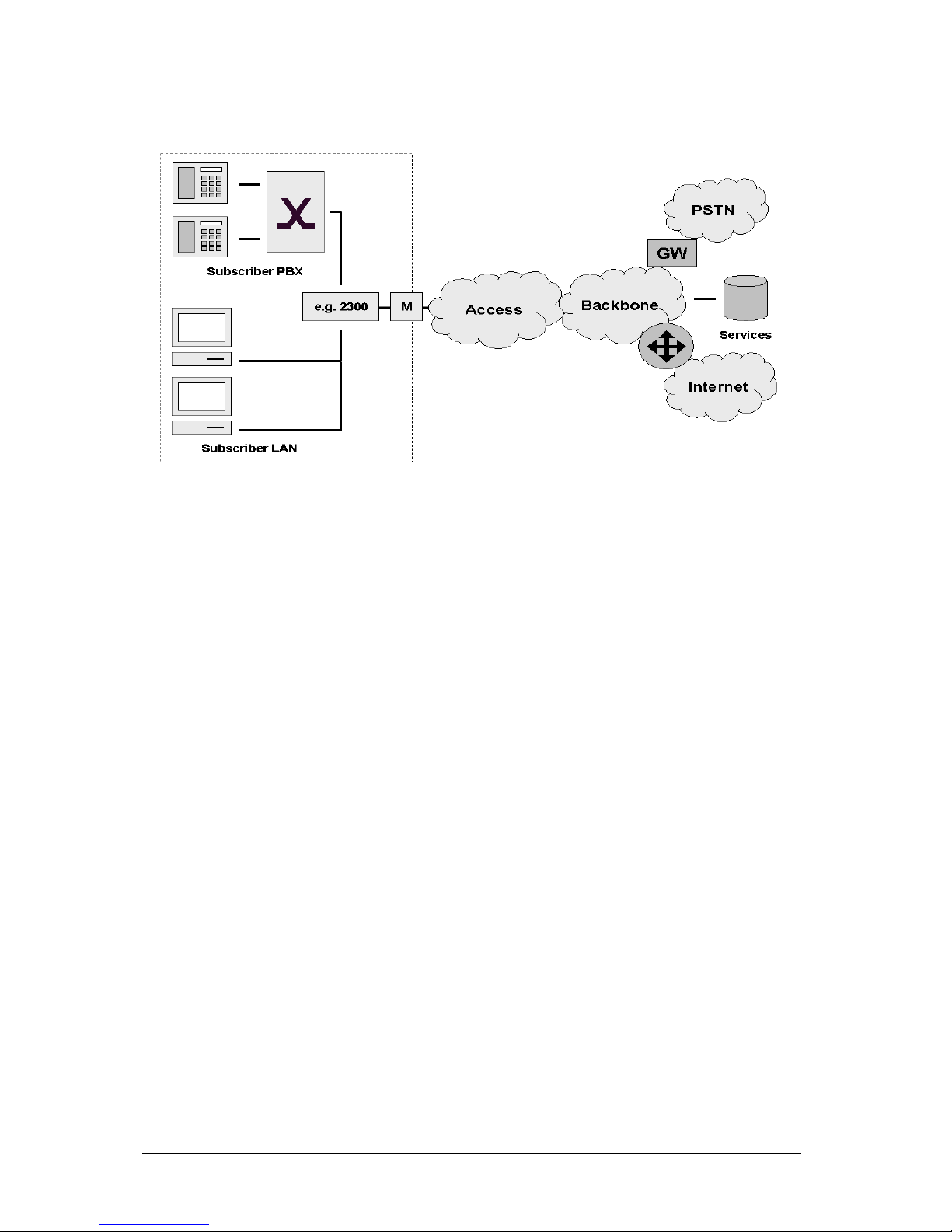
24 Applications
Figure 2-1: Typical Carrier Network Application with a SmartNode 2300
Figure 2-1 shows the deployment of SmartNodes in carrier networks. Each subscriber site is
equipped with a SmartNode that connects the subscriber CPE on one side with the provider network
and services on the other.
Typical services in these networks are softswitch based telephony, PSTN access through V5.2
gateways, PBX networking services, and LAN interconnection.
Typical access technologies for these networks include xDSL, WLL, PowerLine and conventional
leased lines. With the use on an external modem (M) the SmartNode can connect to leased lines or
any bridged-Ethernet broadband access.
2.3 Enterprise Networks
In company owned and operated wide are networks SmartNodes can be used to converge voice and
data communications on the same IP link.
In combination with centralized services such as groupware and unified messaging the SmartNodes
provide migration and investment protection for legacy telephony systems.
Software Configuration Guide Release 2.10, Revision 1.00
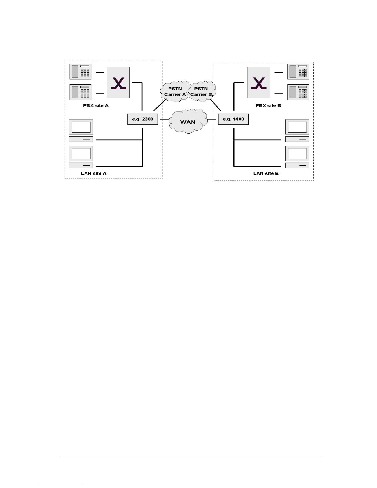
Applications 25
Figure 2-2: Typical Enterprise Network with a SmartNode 1400 and 2300
Figure 2-2 shows the deployment of SmartNodes in enterprise networks. Each site (headquarter,
branch or home office) is equipped with a SmartNode that connects the local LAN and telephony
infrastructure with the IP WAN and the local PSTN carrier.
2.4 LAN Telephony
With its Voice-over-IP gateway features the SmartNode can be used as a standalone gateway for
H.323 LAN voice systems such as LAN based PBXs or call centers.
A standalone gateway has performance reliability and scalability advantages compared with PC based gateway cards. In this application the SmartNode also offers a migration path to enterprise or
carrier networking.
Figure 2-3 shows the deployment of a SmartNode as a LAN voice gateway.
The PSTN connections can be scaled from a single ISDN basic rate access to multiple primary rate
lines. With Q.SIG integration in private PBX networks is also supported.
Software Configuration Guide Release 2.10, Revision 1.00
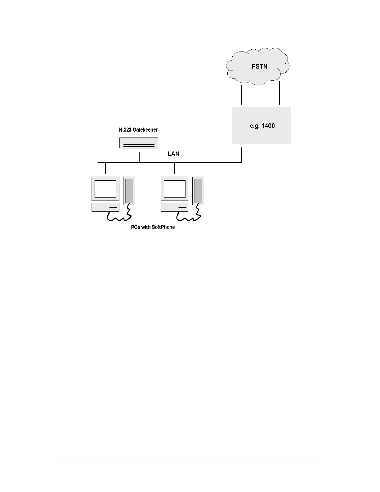
26 Applications
Figure 2-3: Typical LAN Telephony System with a SmartNode 1400 GW
Software Configuration Guide Release 2.10, Revision 1.00

System Overview 27
3 SYSTEM OVERVIEW
This chapter provides an overview of the main elements of a SmartNode system.
The chapter includes the following sections:
• Introduction
• SmartNode hardware platforms
• SmartWare embedded software
• SmartView Management Center tools
3.1 Introduction
A complete SmartNode system or network, as installed in any of the application scenarios
introduced in Chapter 2, “Applications”, is composed of three main elements plus a third-party
network infrastructure:
• The first and most obvious element is the SmartNode devices (also referred to as hardware
platforms or network nodes) that provide the physical connectivity, the CPU and DSP
resources. Throughout the range of SmartNode models all have the common characteristics
of supporting packet-routed and circuit-switched traffic equally well.
• The second, and in many aspects core element, is the embedded software running on the
SmartNode hardware platforms. The software designed by Inalp Networks AG for the
SmartNodes is termed SmartWare. This software is handled as a separate element because it
is as far as possible platform-independent and so provides the same features and
functionality throughout the complete SmartNode model range.
• The third element is the set of SmartView Management Center tools provided to configure and
control SmartWare and SmartNodes in a network. The focus of the SmartView Management
Center tools is on assisting network administrators and operators in handling large numbers
of SmartNode devices. This complements the standard element management interfaces
provided in SmartWare.
• Finally the third-party IP network and transmission infrastructure provides IP connectivity
between the above elements. This infrastructure can range from a simple Ethernet hub or
switch to highly complex networks including multiple access technologies, backbone
transmission and services nodes.
Figure 3-1 illustrates these four elements.
Software Configuration Guide Release 2.10, Revision 1.00
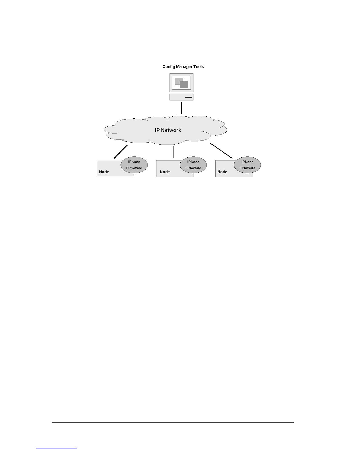
28 System Overview
Figure 3-1: System Overview with a SmartView Management Center
3.2 SmartNode Hardware Platforms
The SmartNode series of devices covers a performance range varying from that suitable for small
office/home office (SOHO) applications to large corporate sites, or in terms of voice channels from 2
channels (one BRI/So) to 60 (two PRI/S2m). The SmartNodes comprise two classes:
• The SmartNode 1000 series compact devices with fixed configured on-board ports
• The SmartNode 2000 series with on-board ports plus expansion slots for individual interface
configurations using a range of optional interface cards (IC).
The basic system model of a Inalp Networks AG SmartNode is depicted in Figure 3-2. Both the
SmartNode 1000 and the 2000 series have three main components:
• 64k circuit switching is supported between on-board ISDN ports and on and between ISDN
and PSTN interface cards. The circuit switching engine uses dedicated hardware resources
and therefore can bypass the VoIP gateway and packet routing engine.
• Gateway (GW), which converts 64k circuits into Internet protocol (IP) packet streams and
vice versa. Voice over IP is supported according the H.323 standard and via Inalp Networks
AG’ patented ISDN over IP (ISoIP) protocol.
• IP Router, with on-board ports and optional data interface cards. The router is QoS enabled
allowing classification, shaping and scheduling of multiple service classes.
Software Configuration Guide Release 2.10, Revision 1.00
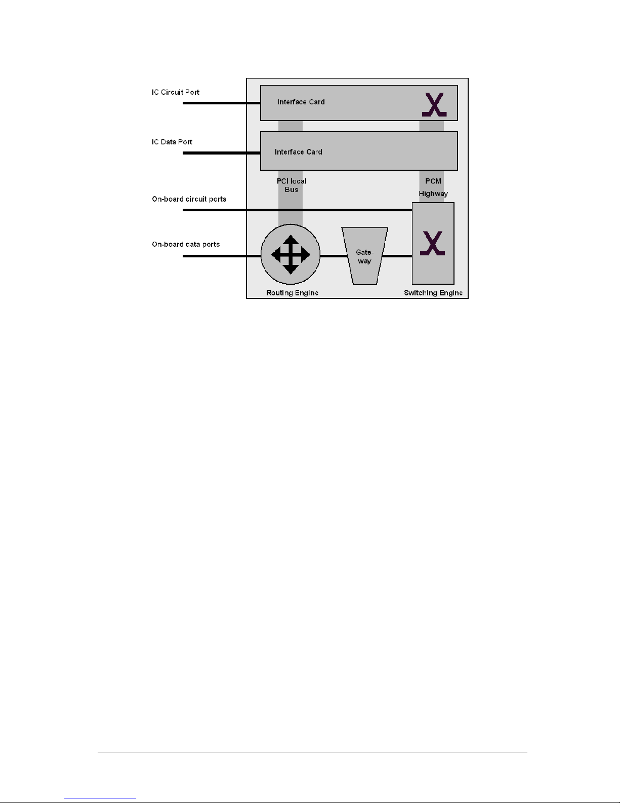
System Overview 29
Figure 3-2: SmartNode System Model
For more detailed hardware information refer to the SmartNode Hardware Installation Guide.
3.3 SmartWare Embedded Software
SmartWare is the application software that runs on the SmartNode hardware platforms. SmartWare
is available in several releases that support all available SmartNode models. Refer to the SmartWare
release notes for detailed information about hardware support.
For each SmartWare release there are platform-specific build numbers. There may be more than one
build per release and platform as updates become available. Refer to the SmartWare release notes for
build numbers and build-specific enhancements and limitations.
A SmartWare build is a binary image file. A SmartWare build is usually divided into several
checksum-protected download files to improve download efficiency and security. The download to
the SmartNode is handled in sequence using a download batchfile. Refer to Chapter 8, “System
Image Handling”, for details on SmartWare image downloads.
In addition to the actual SmartWare images there are several additional embedded software
components that you will encounter:
• The boot loader is a “mini” application that performs basic system checks and which starts the
SmartWare application. The boot loader also provides minimal network services, allowing
the SmartNode to be accessed and upgraded over the network even if the SmartWare
application should not start. The boot loader is installed in the factory and is never
upgraded.
• The PMC loader initializes PMC interface cards when mounted in SmartNode 2000 series
devices. It checks hardware versions and determines whether compatible PMC drivers are
available. The PMC loader may be upgraded together with a SmartWare release.
• PMC driver software performs the runtime tasks on PMC interface cards mounted in
SmartNode 2000 series devices. The PMC drivers are interface card specific and also have
build numbers. Refer to the SmartWare release notes for PMC driver software compatibility.
The PMC drivers may be upgraded together with a SmartWare release or they can be
downloaded individually onto the device flash memory file system.
Software Configuration Guide Release 2.10, Revision 1.00
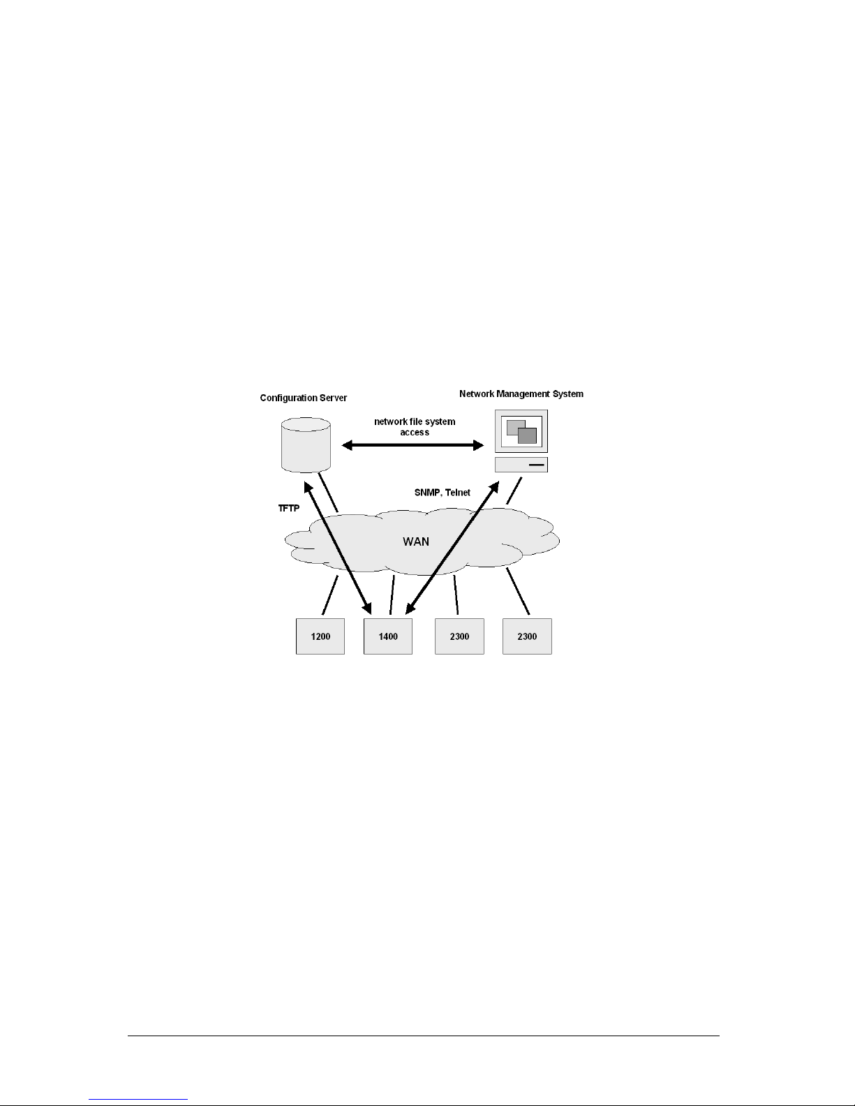
30 System Overview
3.4 SmartView Management Center Tools
SmartWare provides two standard element management interfaces:
• The Command Line Interface (CLI), which supports full online configuration and monitoring
access for the operator
• The SNMP agent and MIB, with an emphasis on inventory and alarm management for
integration in a 3
rd
party Network Management System (NMS)
With the aid of configuration files and TFTP up and downloads, the SmartNodes can also be
managed offline using standard text editors and file systems.
A number of host-based management applications are available to facilitate the generation, editing
and maintenance of configuration files. Tools are also available for the integration of SmartNode
management into standard network management platforms such as HP OpenView.
Figure 3-3: SmartNode Management System
Software Configuration Guide Release 2.10, Revision 1.00
 Loading...