

Inalp Networks SmartNode 1000 Series, SmartNode2000 Series Installation Manual

™
Hardware Installation
Guide
SmartNode 1000, 2000 Series
®
Customer Deliverable Document
Product Number 80-0057
English
Revision 3.01 October 2001
inalp SmartNode

Legal Notice
Copyright © 2001 Inalp Networks AG
All rights reserved. No part of this publication may be reproduced
without prior written permission from Inalp Networks AG.
Inalp Networks AG reserves the right to make changes in specifications and other information contained in this document without prior
notice. The information provided herein is subject to change without
notice. In no event shall Inalp Networks AG or its employees and associated companies be liable for any incidental, special, indirect or
consequential damages whatsoever, including but not limited to lost
profits, arising out of or related to this manual or the information contained herein, even if Inalp Networks AG has ben advised of, known,
or should have known, the possibility of such damages.
Inalp, the Inalp Logo, and SmartNode are registered trademarks of Inalp Networks AG. SmartWare and SmartView are trademarks of Inalp
Networks AG. All other trademarks mentioned in this document are
property of their respective owners.
Declaration of EU Conformity
Inalp Networks AG
Meriedweg 7
CH-3172 Niederwangen
Switzerland.
Concerning the SmartNodes SN1200, SN1400 and SN2300.
The named products fulfil the requirements set by:
73/23/EU as Amended
The Guidelines set by the Advisory Committee for the Harmonisation
of the Legal Requirements of Member States governing electrical
service equipment for use within defined power limits.
89/336/EU as Amended
The Guidelines set by the Advisory Committee for the Harmonisation
of the Legal Requirements of Member States governing resistance
to magnetic interference.

Hardware Installation Guide
Contents
Legal Notice i
Contents i
About This Document v
Objectives v
Audience v
Document Conventions v
Obtaining Service and Support ix
Ordering Documentation ix
Feedback ix
Safety Advice ix
Safety Precautions ix
Safety with Electricity x
Preventing Electrostatic Discharge Damage x
General Observations x
1 Hardware Description SN1200 1
Physical Description 1
Front Panel 1
Rear Panel 1
2 Hardware Description SN1400 5
Physical Description: 5
Front Panel 5
Rear Panel 5
3 Hardware Description SN2300 9
Physical Description: 9
Front Panel 9
Rear Panel 9
Expansion Slots 9
On-board Ports 10
Rack Mounting 11
4 Physical Description IC-4BRV 13
Physical Specification 13
Front Panel 13
Interfaces 13
Description 14
Interface Modes 14
Hardware Bypass 15
Connections 15
S-Bus Line Power 17
inalp networks Contents i

Hardware Installation Guide
Jumper Block Settings 17
5 Physical Description IC-E1V 21
Physical Specification 21
Front Panel 21
Interface 21
Description 22
Interface Modes 22
6 Interface Card Installation 23
Safety Recommendation 23
Installing Interface Cards 23
7 SmartNode Installation 27
Introduction 27
Audience 27
Warnings 27
System Model, SN1000- and 2000-Series 28
SmartNode Deployment 30
Multi-Service Gateway/Router for private Enterprise Networks 32
ISDN Gateway; LAN based PBX or Call Centre Applications 34
Planning Your Installation 35
Network Information 37
Software Tools 38
Power Source 39
Location and Mounting Requirements 39
Access to Chassis 39
Interface Card Configuration 39
Installing an S-Bus Power Module 39
Installing Interface Cards 39
Site Installation: SmartNode 1000 or 2000 Series 39
Connecting Cables 41
Perform Initial Configuration 42
8 Power Module Installation 43
Safety Recommendation 43
Internal PM-48V-int Line Power Module 44
Module Installation 44
Mounting the Internal 48V Power Module 45
External S-Bus Power Supply 47
PM-BRI-ext Phantom Power Supply Unit 47
SmartNode Connection 48
S-Bus Connection 49
9 LED Indications 51
ii
Contents inalp networks

Hardware Installation Guide
Appendix 1 Cabling and Pinouts 53
Connector Types 53
RJ-45 / RJ-48 Connector 53
RJ-12 Connector 53
Port Pinouts 53
Console Port 54
10BaseT / 100BaseT Port 54
BRI Port 55
PRI Port 55
Serial Port 56
Cabling 58
Console 58
10BaseT / 100BaseT 58
V.35 / X.21 60
BRI 60
PRI 61
Index 63
SmartNode Glossary i
inalp networks Contents iii

Hardware Installation Guide
About This Document
Objectives
The aim of this SmartNode Hardware Installation guide is to provide hard-
ware information concerning SmartNode devices and their interface cards.
The installation of the cards and the cabling of the devices is also described. The goal is to enable you to install such devices, alone or under supervision.
The information included in this guide consists of:
l
hardware descriptions of the SmartNodes
l
physical descriptions of the extension interface cards
l
hardware installation instructions
l
LED indications
l
cabling and pinout data.
For software configuration information and initial SmartNode installation refer to the Software Configuration Guide.
The guide describes three SmartNode models that are similar in functionality, but differ in the number and type of interfaces that they support. Because of this some of the information provided may not apply to your
particular SmartNode model.
Audience
The guide is intended primarily for the following audiences:
l
Technical staff who are familiar with electronic circuitry, networking theory and have experience as an electronic or electromechanical technician.
l
System administrators with a basic networking background and experience, but who might not be familiar with the SmartNode.
l
System administrators who are responsible for installing and configuring
networking equipment and who are familiar with the SmartNode.
Document Conventions
Inalp documentation uses the conventions tabulated below to convey instructions and information.
inalp networks About This Document v

Hardware Installation Guide
Table 1: Notice Conventions
Notices Description
Note Contain helpful suggestions or information for
Warning Situation that could cause bodily injury. Be aware
important features and instructions.
of the hazards involved with electrical circuitry.
Warning
Mains Voltage
Situation that could cause bodily injury and equipment destruction.
Caution Situation that could put equipment at risk.
Electrostatic
Discharge
Situation that could put equipment at risk. Electrostatic discharge may result in equipment defects
or diminished reliability. The defect may not be
immediately recognizable.
Table 2: Text Conventions
Text Convention Description
boldface font
Commands and keywords to be
entered at the command line
prompt.
Note
italic font
Otherwise, important information.
Variables for which you supply values.
SmartWare Users Guide
Cross references to other documents.
screen font
\Server\node\batchfile
[...] Keywords or arguments within
vi
About This Document inalp networks
Information as it appears on the
screen.
File paths and names.
[brackets] are optional.

Hardware Installation Guide
Text Convention Description
x ¦ y ¦ z A selection of command parame-
ters separated by vertical bars.
One parameter needs to be
entered.
inalp networks About This Document vii

Hardware Installation Guide
Obtaining Service and Support
For service and support for an Inalp SmartNode product purchased from a
reseller, contact the reseller.
Ordering Documentation
Inalp documentation and additional supporting literature are available on a
CD-ROM which is shipped with your product. To order additional copies of
the documentation on CD-ROM contact your local sales representative or
call customer service.
Feedback
Your comments can help us to improve our user documentation. If you
have suggestions concerning this manual, send an e-mail containing your
comment(s) to:
documentation@inalp.com
Please include the following information with your e-mail:
l
document title and Revision Number: eg. SmartNode Hardware Instal-
lation Guide Rev. 3.00
l
document part number. Part numbers are located on the last page of
the document, printed in a frame: eg. 80-0057
l
chapter title, name and page number: eg. Chapter 1 ’Port Numbering
Conventions’, page 1.
Note: Do not use this e-mail address for technical support questions. For
information about contacting Technical Support see the previous section
"Obtaining Service and Support".
Safety Advice
Safety Precautions
This section lists safety warnings that you should be aware of before installing a SmartNode or an interface card in a SmartNode.
Follow these guidelines to ensure general safety:
l
Install the SmartNode in an environment with 5% to 80% relative
humidity and a Degree of Pollution 2
l
Install the SmartNode in an environment with a temperature range of 0
to +40
l
Keep tools away from walk areas where you or others could fall over
deg. Celsius
them
inalp networks Obtaining Service and Support ix

Hardware Installation Guide
l
Do not wear lose clothing that could get caught in the chassis. Fasten
your tie or scarf and roll up your sleeves
l
Do not perform any action that creates potential hazard to people or
makes equipment unsafe.
Safety with Electricity
Warning Mains Voltage: Do NOT open the case when the power cord is
connected. For systems without a power switch, line voltages are present
within the power supply when the power cord is connected.
Warning: Hazardous network voltages are present in WAN ports regardless of whether power to the SmartNode is ON or OFF. To avoid electric
shock, use caution when near WAN ports. When detaching cables, detach
the end away from the SmartNode first.
Warning: Before opening the chassis, disconnect the telephone network
cables to avoid contact with telephone line voltages.
Warning: Do not work on the system or connect or disconnect cables during periods of lightning activity.
Warning: Ultimate disposal of this equipment must be handled according
to all applicable national laws and regulations.
Preventing Electrostatic Discharge Damage
Opening the SmartNode, handling Interface Cards
When the SmartNode case is opened to install interface cards take the following precautions. You should place the interface card on its shielded
plastic bag if you lay it on your bench.
Caution Electrostatic Discharge: Electrostatic Discharge (ESD) can damage equipment and impair electrical circuitry. It occurs when electronic
printed circuit cards are improperly handled and can result in complete or
intermittent failures. Always follow ESD prevention procedures when removing and replacing cards. Ensure that the SmartNode chassis is electrically connected to earth ground. Wear an ESD-preventive wrist strap,
ensuring that it makes good skin contact. Connect the clip to an unpainted
surface of the chassis frame to safely channel unwanted ESD voltages to
ground. To properly guard against ESD damage and shocks, the wrist strap
and cord must operate effectively. If no wrist strap is available, ground
yourself by touching the metal part of the chassis.
Caution For safety, periodically check the resistance value of the antistatic
wrist strap, which should be between 1 and 10 M Ohm.
General Observations
l
Clean case with a soft slightly moist anti-static cloth
x
Safety Advice inalp networks

Hardware Installation Guide
l
Place unit on a flat surface (or optionally in a rack for the SN2300) and
ensure free air circulation
l
Avoid exposing the unit to direct sunlight and other heat sources
l
Protect the unit from moisture, vapors and aggressive liquids
inalp networks Safety Advice xi

Hardware Installation Guide
1 Hardware Description SN1200
The SmartNode model SN1200 is a compact voice-data access device
which supports two voice channels. The user interfaces consist of one
ISDN BRI and one Ethernet 10bT. Network access is provided by one ISDN
BRI and one Ethernet 10bT. It is suitable for home office or small office applications. The ventilated metal case may be placed on a desktop or be
wall-mounted. The SN1200 complies with all relevant EU directives.
Physical Description
l
Chassis W / H / D: 220 / 40 / 160 mm
l
Weight: 600g
l
CPU Motorola MPC850 @ 50MHz
l
Memory 16MB SDRAM
l
Flash memory 4MB
l
2 channel DSP
l
Power dissipation 4W
l
Power supply AC 100 - 240 V, 50 - 60 Hz, 70 mA
Front Panel
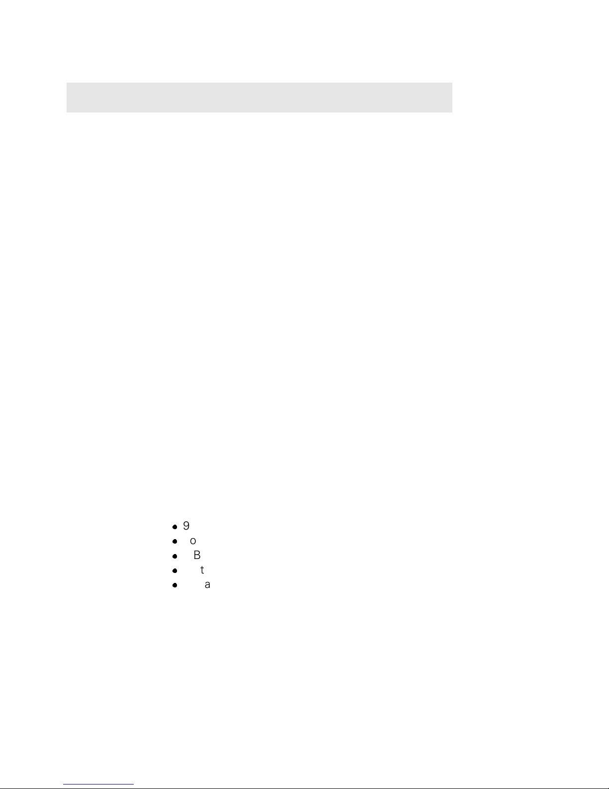
The front view of the SmartNode 1200 is depicted in Figure 1.
Figure 1: SmartNode 1200 Front View
Two LEDs (POWER, RUN) indicate the device status.
Four LEDs (BRI0, BRI1, ETH0, ETH1) indicate the status of the interfaces.
See Chap 9 for detailed information on LED indications.
Rear Panel
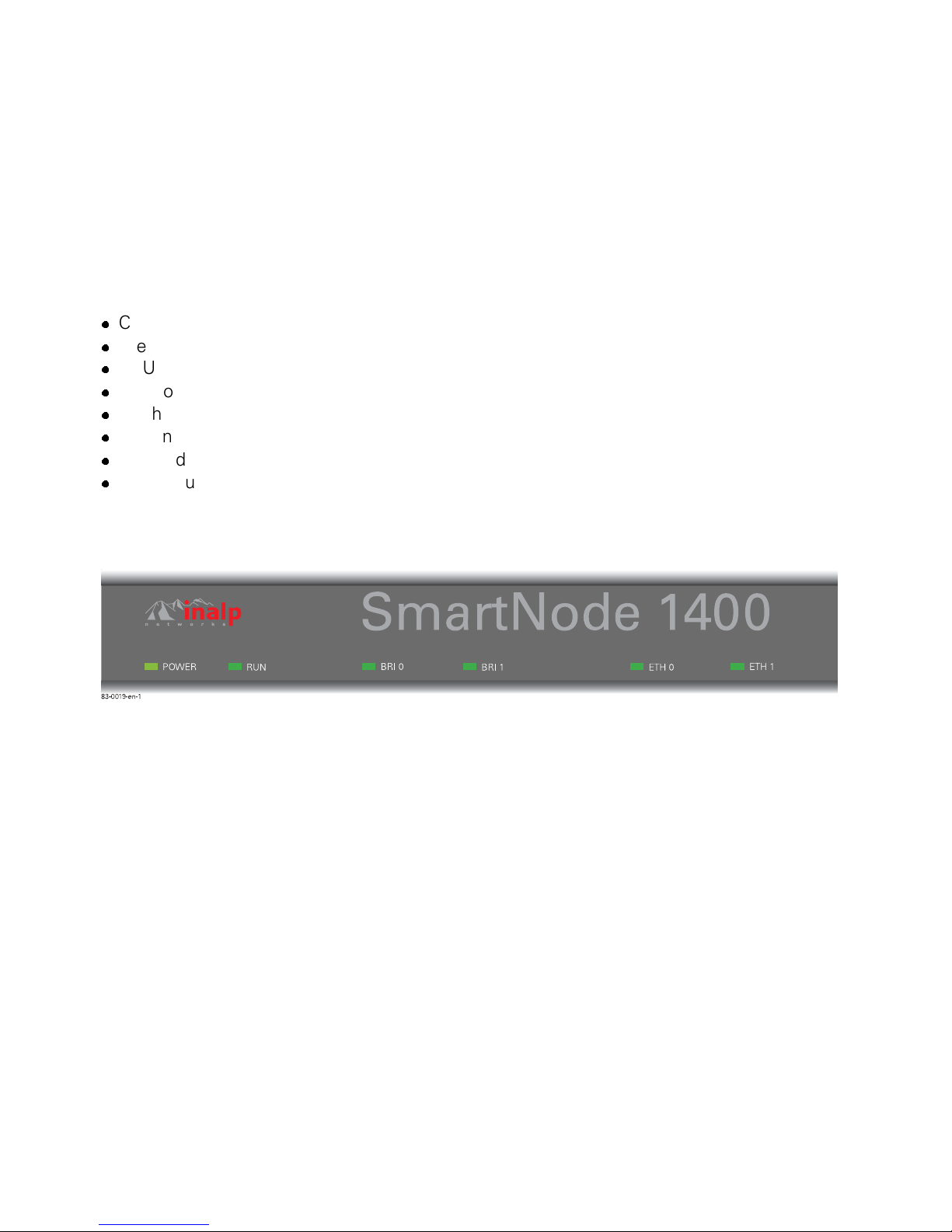
The rear view of the SmartNode 1200 is depicted in Figure 2. Two ’LINK’
LEDs indicate the status of the Ethernet connections, and two ’L2’ LEDs
the status of the BRI interfaces. See Appendix 1 for connection cable and
pinout data.
inalp networks Hardware Description SN1200 1

Hardware Installation Guide
Figure 2: SmartNode 1200 Rear Panel
The ports available are tabulated below. The ports are labelled with the interface name and type above and below each socket, as in the Port column
of the table.
Port Description
ETH 0 10BaseT
(Modem)
ETH 1 10BaseT
(LAN)
10BaseT Ethernet RJ-45 socket to connect the
SmartNode with an Ethernet device. This is usually
a transmission modem, ie. cable or DSL modem.
ETH 0 is a host port; depending on the pinout of the
modem, it can be connected with a straight wired
(1:1) or a crossover cable. The ’LINK’ LED to the left
of the connector is lit when the port is connected
correctly to an active Ethernet device.
10BaseT Ethernet RJ-45 socket to connect the
SmartNode with an Ethernet device, usually a LAN
hub or switch. ETH 1 is a host port; it can be connected with a straight wired (1:1) to a hub or a crossover cable to a host (PC) port. The ’LINK’ LED to the
left of the connector is lit when the port is connected
correctly to an active Ethernet device.
2
Hardware Description SN1200 inalp networks
Port Description
Hardware Installation Guide
BRI 0 ISDN T
(Line)
BRI 1 ISDN S
(Phone)
ISDN BRI RJ-45 socket to connect the SmartNode
with an ISDN Network Termination (NT). The interface may be used as a fallback port. The ’L2’ LED to
the left of the connector is lit when the port is connected correctly to an active ISDN device (Layer 1is
up). The interface is internally terminated at 100
Ohm.
It may be powered by an external power supply to
feed TEs connected to BRI 1. Refer to Appendix 1
for connection details.
Note: External S-Bus power supplies must comply
with the voltage and current limits set by ISDN standards, ie. max. 40VDC and 200mA.
Note: The ’L2’ LED indication depends on the connected device.
ISDN BRI RJ-45 socket to connect the SmartNode
with an ISDN S-Bus, e.g. a PBX. The ’L2’ LED to the
left of the connector is lit when the port is connected
correctly to an active ISDN device (Layer 1 is up).
The interface is internally terminated at 100 Ohm.
Console
(RS-232)
Note: The ’L2’ LED indication depends on the connected device.
RS-232 RJ-45 connector to connect the SmartNode
with a serial terminal such as a PC or Workstation
with a RS-232 interface, with the following settings:
l
9600 Baud
l
no parity
l
8 Bit
l
1 Stop bit
l
1 Start bit
Warning: Do NOT plug in an ISDN connection. The
voltage on the S-Bus may permanently damage the
console interface.
inalp networks Hardware Description SN1200 3

Hardware Installation Guide
Port Description
Reset button The button has three different functions:
Manual Restart: During normal operation pressing
and releasing the reset button will cause a system
reboot. The application will be restarted without any
change to the existing SW configuration.
Restoration: Pressing and holding the reset button
for 5 seconds will restore the factory configuration
and automatically reboot the system.
Caution: in this case the existing IP SW configuration is lost.
Boot loader: Powering the SmartNode while pressing the reset button for 5 seconds will cause the
factory-fitted boot loader to start in place of the
application. The boot loader uses a minimal set of
parameters. In case the application does not start
correctly, the boot loader can be used as a fallback
to download a new software version.
100 - 240VAC
50 / 60 Hz
Electricity supply socket for mains power cable.
4
Hardware Description SN1200 inalp networks
Hardware Installation Guide
2 Hardware Description SN1400
The SN1400 is a compact voice-data access device which supports four
voice channels. The interfaces consist of two ISDN BRI and two Ethernet
10bT. It is suitable for enterprise networking and small office environments. The ventilated metal case can be wall-mounted or placed on a desktop.The SN1400 complies with all relevant EU directives.
Physical Description:
l
Chassis W / H / D: 220 / 40 / 160 mm
l
Weight: 600g
l
CPU Motorola MPC850 @ 50MHz
l
Memory 16MB SDRAM
l
Flash 4MB
l
4 channel DSP
l
Power dissipation 4W
l
Power supply AC 100 - 240 V, 50 - 60 Hz, 70 mA
Front Panel
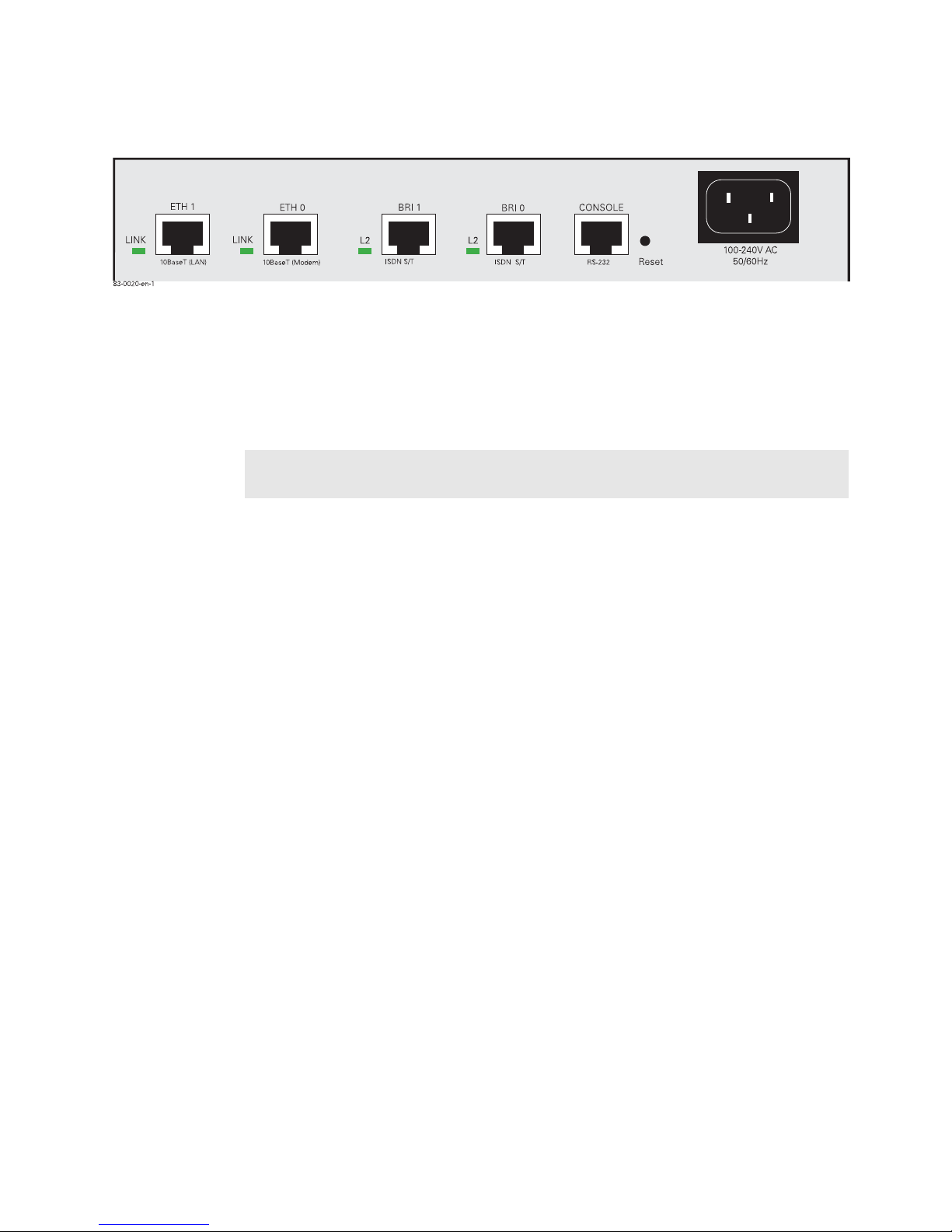
The front view of the SmartNode 1400 is depicted in Figure 1.
Figure 1: SmartNode 1400 Front View
Two LEDs (’POWER’, ’RUN’) indicate the device status.
Four LEDs (’BRI0’, ’BRI1’, ’ETH0’, ’ETH1’) indicate the status of the interfaces. See Chapter 9 for detailed information on LED states.
Rear Panel
The rear view of the SmartNode 1400 is depicted in Figure 2. Two ’LINK’
LEDs show the Ethernet status and two ’L2’ LEDs show the BRI status.
See Appendix 1 for connection cables and pinout data.
inalp networks Hardware Description SN1400 5
Hardware Installation Guide
Figure 2: SmartNode 1400 Rear View
The available ports are tabulated below. The ports are labelled with the interface type above each socket, as shown in the Port column of the table
below.
Port Description
ETH 0 10BaseT
(Modem)
ETH 1 10BaseT
(LAN)
10BaseT Ethernet RJ-45 socket to connect the
SmartNode with an Ethernet device This is usually a
transmission modem, ie. cable or DSL modem. ETH
0 is a host port; depending on the pinout of the modem, it can be connected with a straight wired (1:1)
or with a crossover cable. The ’LINK’ LED to the left
of the connector is lit when the port is connected
correctly to an active Ethernet device.
10BaseT Ethernet RJ-45 socket to connect the
SmartNode with an Ethernet device, usually a LAN
hub or switch. ETH 1 is a host port; it can be connected with a straight wired (1:1) to a hub or with a
crossover cable to a host (PC) port. The ’LINK’ LED
to the left of the connector is lit when the port is connected correctly to an active Ethernet device.
6
Hardware Description SN1400 inalp networks

Hardware Installation Guide
Port Description
BRI 0 ISDN S/T ISDN BRI RJ-45 socket to connect the SmartNode
with an ISDN device over a S/T bus, eg. a PBX or a
NT. The interface may be used as fallback if connected to a NT. The ’L2’ LED to the left of the connector
is lit when the port is connected correctly to an active ISDN device (Layer 1 is up). The pin-out is configurable; see the document SmartWare Software
Configuration Guide. The interface is internally terminated at 100 Ohm.
It may be powered by an external power supply to
feed TEs connected to BRI 1. Refer to Appendix 1
for details.
Note: External S-Bus power supplies must comply
with the voltage and current limits set by ISDN standards, ie. max. 40VDC and 200mA maximum.
Note: The ’L2’ LED indications depend on the connected device.
BRI 1 ISDN S/T ISDN BRI RJ-45 socket to connect the SmartNode
with an ISDN device over a S/T bus, such as a PBX.
The ’L2’ LED to the left of the connector is lit when
the port is connected correctly to an active ISDN device (Layer 1 is up). The pin-out is configurable; see
the document SmartWare Software Configuration
Guide. The interface is internally terminated at 100
Ohm.
Note: The ’L2’ LED indications depend on the connected device.
inalp networks Hardware Description SN1400 7

Hardware Installation Guide
Port Description
Console
(RS-232)
RS-232 RJ-45 connector to connect the SmartNode
with a serial terminal such as a PC or workstation
with an RS-232 interface, with the following settings:
l
9600 Baud
l
no parity
l
8 Bit
l
1 Stop bit
l
1 Start bit
Warning: Do NOT plug in an ISDN connector. The
voltage on the S-Bus may permanently damage the
console interface.
Reset button The button has three different functions:
Manual Restart: During normal operation pressing
and releasing the reset button will cause a system
reboot. The application will be restarted without any
change to the SW configuration.
Restoration: Pressing and holding the reset button
for 5 seconds will restore the factory configuration
and automatically reboot the system.
100-240VAC
50 / 60 Hz
Caution: in this case the existing IP SW configuration is lost.
Boot loader: Powering the SmartNode while pressing the reset button for 5 seconds will cause the
factory-fitted boot loader to start in place of the
application. The boot loader uses a minimal set of
parameters. In case the application does not start
correctly, the boot loader can be used as a fallback
to download a new software version.
Electricity supply socket for mains power cable.
8
Hardware Description SN1400 inalp networks
Hardware Installation Guide
3 Hardware Description SN2300
The SN2300 is a powerful multi-service access device. The 19in aluminium
chassis can be rack-mounted, and provides three expansion slots for interface cards. The SN2300 complies with all relevant EU directives.
Physical Description:
l
Chassis W/H/D 440 / 42 / 265 mm
l
Weight 1650g
l
CPU Motorola MPC860 @ 50 Mhz
l
Memory 16 MB SDRAM
l
Flash 4 MB
l
Power dissipation 30 W, fully loaded interface card (IC) slots, without
internal 48V power module PM-48V-int
l
Power supply AC 100 - 230 V, 50 - 60 Hz
Front Panel
The front view of the SmartNode 2300 is depicted in Figure 1.
Figure 1: SmartNode 2300 Front View
Three front LEDs (’PWR’, ’RUN’, ’ACT’) indicate the status of the device.
See Chapter 9 for detailed information on the LED states.
Rear Panel
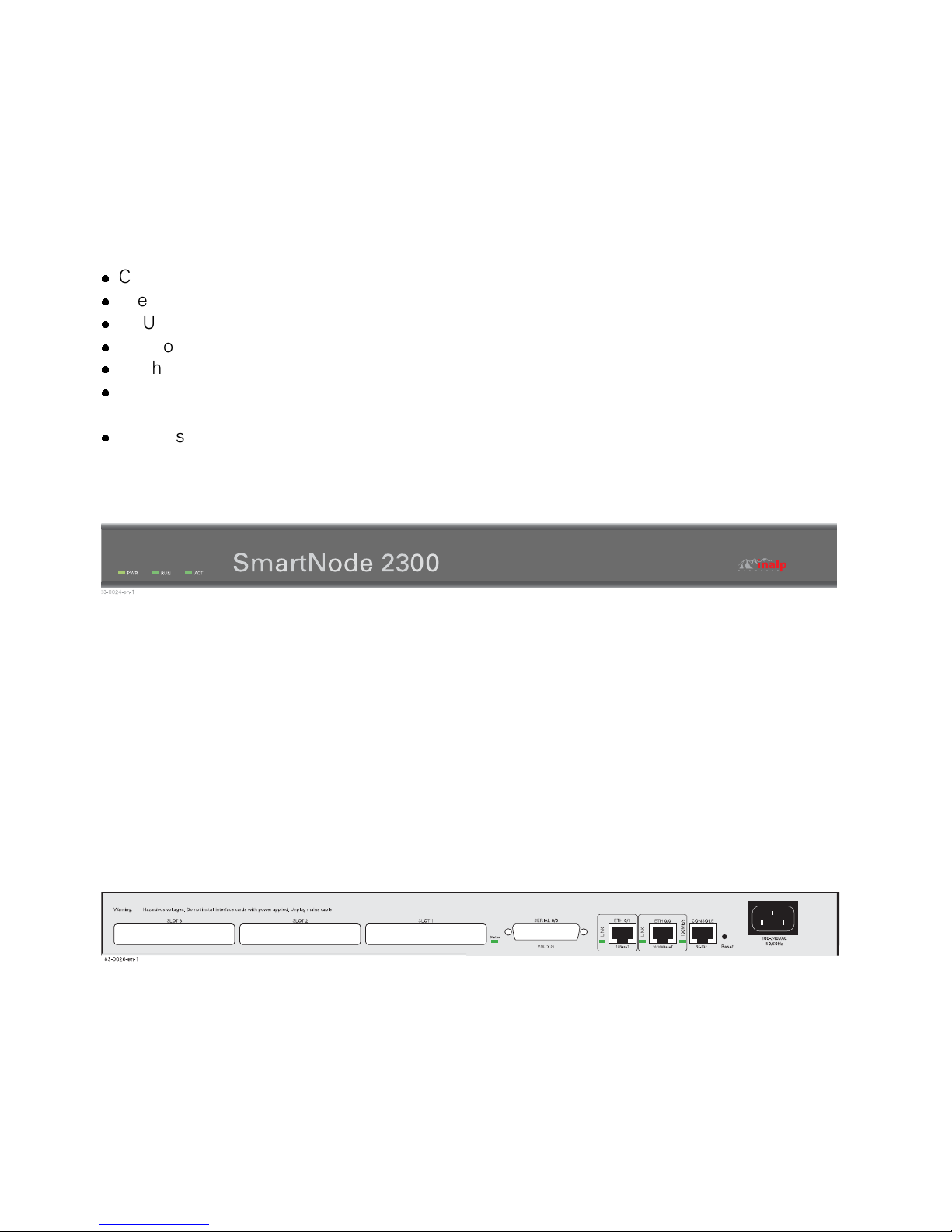
The rear view of the device is depicted in Figure 2. There are three expansion slots for optional interface cards, and four board-mounted sockets.
Three LEDs (’Status’, ’LINK’, ’100Mb/s’) indicate the status of the on-board
interfaces.
See Appendix 1 for cabling connections and pinout data.
Figure 2: SmartNode 2300 Rear View
Expansion Slots
Three slots, labelled SLOT 1 - SLOT 3, accept different PMC interface cards
to integrate voice and data over IP networks.
inalp networks Hardware Description SN2300 9
Hardware Installation Guide
On-board Ports
Three board-mounted network interfaces are available for use independently of those which are available with interface cards mounted in SLOT
1 - SLOT 3.
The board-mounted ports are tabulated below. The Port column of the table shows the port’s label and the interface type.
Port Description
SERIAL 0/0
(V.35 / X.21)
ETH 0/1
(10BaseT)
ETH 0/0
(10 / 100BaseT)
Console
(RS-232)
DB25 socket providing a V.35 and X.21 interface for
Leased Lines up to 2Mbit/s. A LED to the left of the
connector indicates its status.
10BaseT Ethernet RJ-45 socket to connect the
SmartNode with an Ethernet device, such as a wide
area transmission modem, Ethernet hub or switch.
ETH 0/1 is a host port; it can be connected with a
straight [wired (1:1)] to a hub or a crossover cable to
a host port.
The ’LINK’ LED to the left of the connector is lit
when the port is connected correctly to an active
Ethernet device.
10 / 100BaseT Ethernet RJ-45 socket. The interface
has similar functionality to ETH 0/1 except for the
option of 100BaseT capability.
The ’100Mb/s’ LED is lit when the port is connected
correctly to an active 100BaseT Ethernet device.
RS-232 RJ-45 connector to connect the SmartNode
with a serial terminal such as a PC or workstation
with a RS-232 interface, with the following settings:
l
9600 Baud
l
no parity
l
8 Bit
l
1 Stop bit
l
1 Start bit
10
Hardware Description SN2300 inalp networks
Caution: Do NOT plug in an ISDN connector. The
voltage on the S-Bus may permanently damage the
console interface.

Hardware Installation Guide
Port Description
Reset Button The button has three different functions:
Manual Restart: During normal operation pressing
and releasing the reset button will cause a system
reboot. The application will be restarted without any
change to the existing SW configuration.
Restoration: Pressing and holding the reset button
for 5 seconds will restore the factory configuration
and automatically reboot the system.
Caution: in this case the existing IP SW configuration is lost
Boot loader: Powering the SmartNode while pressing the reset button for 5 seconds will cause the
factory fitted boot loader to start in place of the
application. The boot loader uses a minimal set of
parameters. In case the application does not start
correctly, the boot loader can be used as a fallback
to download a new software version.
100-240V AC
50 / 60 Hz
Power supply connector for mains electricity supply.
Rack Mounting
If you want to mount the SN2300 in a 19’ rack, see Chapter 7 of this document.
inalp networks Hardware Description SN2300 11
Hardware Installation Guide
4 Physical Description IC-4BRV
The IC-4BRV interface card is designed for the SmartNode 2000 series of
devices. It meets IEEE P1386.1 standards and provides 4 BRI ISDN ports.
Physical Specification
l
Size W / H / D: 149 / 15 / 74 mm
l
Weight: 100 g
l
PMC card with 32bit PCI bus
l
CPU Motorola MPC850 @ 50 MHz
l
Memory 8MB SDRAM
l
Power dissipation < 3W
l
Optional internal S-Bus power supply PM-48V-int: up to 2.5W per BRI
port
Front Panel
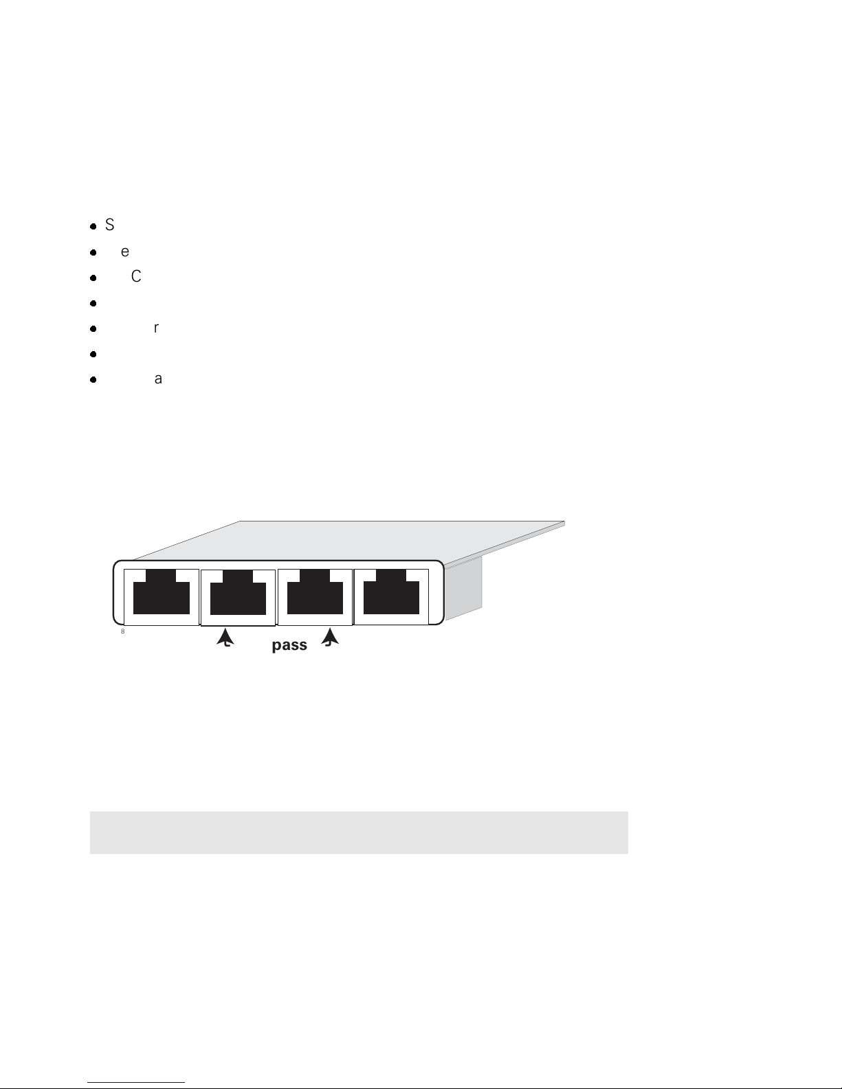
The front view of the ’IC-4BRV’ interface card is depicted in Figure 1. The
individual sockets are labelled on the bezel.
33333
BRI 3
83-0075-en-1
BRI 2
Bypass
Figure 1: IC-4BRV Front View
BRI 1
BRI 0
IC-4BRV
Ports
The card provides the ports tabulated below. Each one is terminated internally at 100 Ohm. See App. 1 for pinout data.
Port Description
BRI 0 ISDN BRI RJ-45 socket to connect the SmartNode with an
ISDN terminal over an S or S/T interface.
inalp networks Physical Description IC-4BRV 13
 Loading...