

In2 Networks Energy ICM Quick Start Manual
In2 Networks Energy ICM Quick Start
In2
Networks
Energy ICM
Quick Start
In2 Networks Energy ICM Quick Start
Quick Hardware Installation
Follow these steps to install the Internet Control Module (Energy ICM):
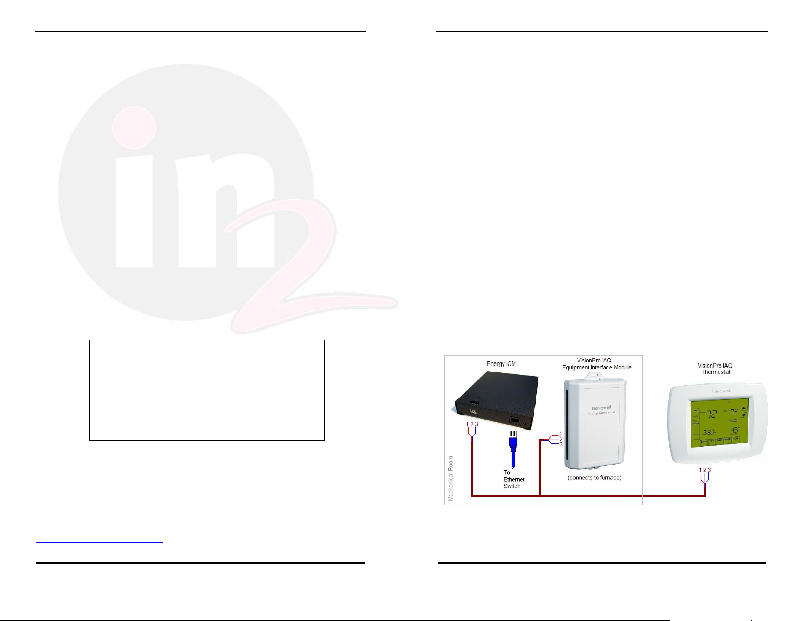
1. Install the ICM. Attach the Energy ICM to the wall near the
EnviraCom Equipment Interface Module which is normally
installed near the heating or cooling equipment in the mechanical
room. The Energy ICM can also be mounted near the structured
wiring panel, and connected to the Equipment Interface Module
using standard HVAC wiring. Use caution when installing the
ICM enclosure to avoid damage to the PCB.
2. Connect the HVAC wiring. Connect HVAC wiring between the
Energy ICM and the Equipment Interface Module. Be sure that
pin 1 on the Energy ICM connects to pin 1 on the EIM, pin 2 to
pin 2, and pin 3 to pin 3. Some patriotic HVAC contractors use
the wiring color code Red, White and Blue for pins 1, 2 and 3.
3. Plug in the Ethernet cable. Plug one end of the network cable
into the RJ-45 on the Energy ICM. Connect the other end to the
network router (or a network attached hub or switch).
4. Connect the Power Supply. Plug the included 12V DC 300mA
AC adapter into a nearby 120V AC outlet. Plug the other end
into the ICM power connector.
Quick Start Guide
For the In2 Networks
Internet Control Module
Rev 1.02
August 2007
The complete setup documentation can be found on the web at:
www.in2nets.com/support
In2 Networks • 79 West 4500 South, Suite 15, Murray, UT 84107 • 801.685-8778 •
www.in2nets.com
Be sure to follow any local codes and standard practices for installing a
low voltage device.
In2 Networks • 79 West 4500 South, Suite 15, Murray, UT 84107 • 801.685-8778 •
www.in2nets.com
In2 Networks Energy ICM Quick Start
Ethernet Network Overview
The In2 Networking Primer reviews the associated networking and
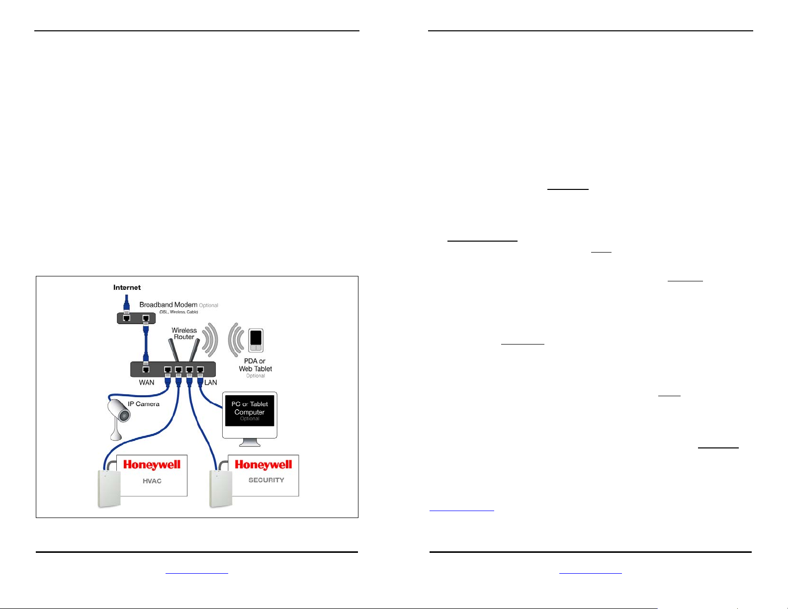
security topics in more detail. The following diagram shows a typical
Ethernet network, with a Honeywell Security ICM and HVAC ICM
attached. The key components in the Ethernet network are:
1. Ethernet Router. The router provides IP addresses for the
network devices, and allows all the devices on the network to
share a single connection to the Internet. A wireless router
allows communication with wireless devices like PDAs and PCs.
2. Broadband Modem. This makes the physical connection to an
internet service provider (ISP). This typically uses Digital
Subscriber Line technology over telephone lines (DSL), or Cable
Modem technology over the cable television network. A
broadband connection is required for email and remote access.
3. Computer. A PC can be used to control the system as long as it
supports a network connection and Internet Explorer.
In2 Networks Energy ICM Quick Start
Software Quick Start
The ICM contains a web server, which allows it to operate without
requiring a special software installation. To access the ICM from a local
computer, follow these instructions:
1. Connect to the network. Make sure the computer is connected to
the network router using either a hard-wired or a wireless connection.
The PC is connected if you can access a web page on the Internet
from the web browser.
2. Browse to the ICM. Make sure the ICM has been powered on for
more than 60 seconds, so it can start up and obtain an IP address
from the router. Enter myhome
browser on the networked PC. The ICM will respond with a blank
web control page.
3. Run Setup. Access the setup pages on the ICM by entering
myhome/setup
setup the ICM by clicking on the Next
Setup can be completed in only 3 steps:
a. Devices. Set the device file from the Devices
in the web browser on the PC. Follow the wizard to
left side of the setup page. Under the port named Serial
1, select the device file that matches the serial device
connected to the ICM, and press the Next button.
in the address bar or the web
button on the first setup page.
link on the
In2 Networks • 79 West 4500 South, Suite 15, Murray, UT 84107 • 801.685-8778 •
www.in2nets.com
b. Configure. Configure the serial device by accessing the
Configure
are specific to the device selected for the serial port.
Follow the instructions on the configuration page to
customize the ICM software for the particular installation.
c. Save. Click the Save link, then the Save
the configuration into permanent flash memory on the
ICM.
The ICM is now configured and ready to use from any web browser in
the home. Access the control page from any PC by entering myhome
the web browser address bar.
The ICM control page uses a Java applet to show feedback from the
system in real time. Some computers may not have the Java virtual
machine loaded, which is required to run the Java applet. Go to
http://java.com
window at the top of the control page does not show feedback or if it
shows a small red X.
In2 Networks • 79 West 4500 South, Suite 15, Murray, UT 84107 • 801.685-8778 •
to download the free Java virtual machine if the feedback
link. The configuration page has options that
button to write
in
www.in2nets.com
 Loading...