

IMV CORPORATION VM-7024H Instruction Manual

INSTRUCTION MANUAL
Portable Vibrometer: VM-7024H
IMV CORPORATION
Document Number TVE-6-3792E
I s s u a n c e D a t e
October 3, 2012
V e r s i o n 1.0.3
Pages (Incl. Cover) 36

Revision History
Date Rev Details
May 8, 2012 1.0.0 New Issue
July 24, 2012 1.0.1 Corrected Figures and phrases.
August, 2012 1.0.2 Corrected Phrases.
Oct. 3, 2012 1.0.3 Add the sampling frequency for Data Save

Table of Contents
1. Introduction .................................................................................................................................1
1-1. Panel Description ..................................................................................................................2
1-2. Package Contents..................................................................................................................3
2. Outline .........................................................................................................................................4
2-1. SmartVibro ............................................................................................................................4
2-2 Features .................................................................................................................................4
3. Measurement ...............................................................................................................................5
3.1 Before Getting Started............................................................................................................6
3-2. Measurement Screen .............................................................................................................7
3-3. Operations during Measurement ...........................................................................................8
4. Setting........................................................................................................................................10
4-1. Mode Setting .......................................................................................................................11
4-2. Calculation Setting ..............................................................................................................11
4-3. Filter ....................................................................................................................................14
4-4. Auto Range..........................................................................................................................15
4-5. Self Check ...........................................................................................................................16
4-6. Averaging ............................................................................................................................17
4-7. Sensitivity Setting of AC and DC Output .............................................................................18
4-7. Battery Setting ....................................................................................................................20
4-8. Auto Power OFF ..................................................................................................................20
4-9. Contrast...............................................................................................................................20
4-10. Language Setting ..............................................................................................................21
4-11. Version Information...........................................................................................................22
4-12. Battery Indicator ...............................................................................................................23
5. FFT and Data Dave ....................................................................................................................24
5-1.FFT .......................................................................................................................................24
5-1-1.FFT Indication ...............................................................................................................24
5-1-2. FFT Setting ...................................................................................................................25
5-2 Waveform Save ....................................................................................................................26
5-2-1. Waveform Data Save ....................................................................................................26
5-2-2. Data Save Settings .......................................................................................................29
6. Conversion Table........................................................................................................................30
7. Specif ications .............................................................................................................................31
7-1. SmartVibro ..........................................................................................................................31
7-2. Pickup..................................................................................................................................31
8. Troubleshooting .........................................................................................................................32
9. Precautions ................................................................................................................................32
10. Fix the Pickup with Magnet ......................................................................................................32
11. Definitions ................................................................................................................................33

1
1. Introduction
We truly appreciate your purchase.
Please read this manual carefully before use and follow the cautions below for your safety.
Should you have any inquiries or find a problem during use, please consult our sales office near you or IMV
quality assurance department.
1. If the subject of the measurement could be hot, rotating, or near the movable
parts, assure the safety and fix the pickup for measurement.
Do NOT hold the pickup manually in these cases to avoid any possible accidents;
including burning yourself, and entangled cables.
2. Follow the instructions printed on the battery for replacement and disposal of used
batteries. Pay attention to the polarity of the battery for installation.
CAUTION
2
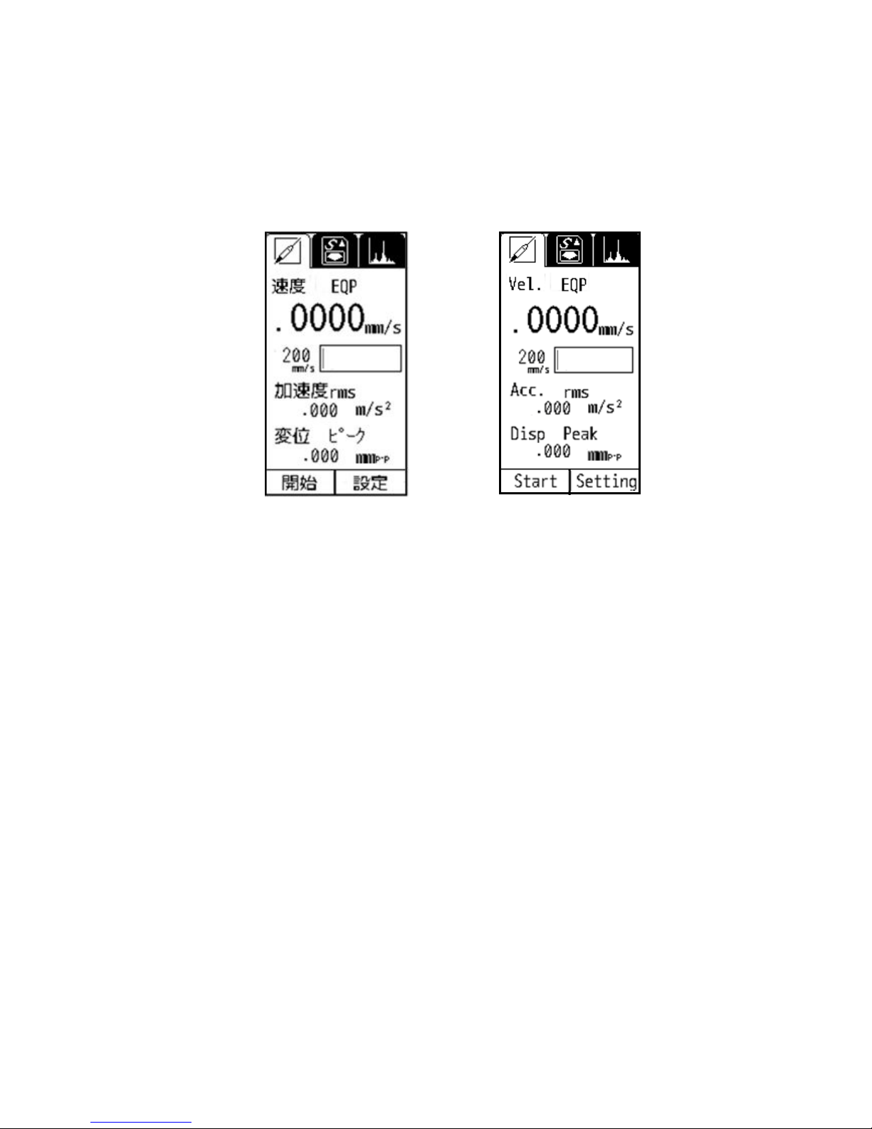
1-1. Panel Description
Display of the VM-7024H can be switched from Japanese to English, and vice versa.
Below figures are example of a display in Japanese and English.
Japanese English

3
1-2. Package Contents
Product and Accessories for the VM-7024H
(1) Basic Product and Accessories
Products Qty Model Note Figure
Main Unit
SmartVibro 1 VM-7024H
Pickup 1 VP-7000L
Piezoresistive Acceleration
Type
SmartVibro Cable 1 CP-7000
3m straight cable with
metal connectors at both
ends.
Output Cable 1
-
1.5m cable with a plug at
one end.
For output to a stroboscope
or recorder, etc.
Battery 1
-
AA Alkaline batteries
Instruction Manual
1
-
With inspection report
Accessories
SD Card 1
-
(2) Optional Accessories
Products Qty Model Note
1
Long Pickup Cable CE-7000 (10m)
To keep a distance from
the subject of
measurement.
(Example)
2
Magnet MB-PB
To fix the pickup on the
subject of measurement.
3
Cover PC-3024 Silicone jacket
4
AC Adapter PS-3024-S AC100-240V
5
Carrying Case C-3024
To store the SmartVibro
and pickup.
Specifications and appearances of the items above are subject to change without notice.

4
2. Outline
2-1. SmartVibro
SmartVibro is a portable vibration meter with high-sensitivity and accuracy to measure micro vibration
of super low frequency. Its application varies widely; measuring and analyzing vibrations, evaluation
and maintenance of the ground and/or floor of various architectural constructions, precision machines
in the laser and semiconductor industries, and low-speed machineries in energy harvesting and
hydroelectric generation.
2-2 Features
■Frequency Range
0.3 – 100Hz; Sensitivity: Full scale 0.1m/s2 (Equivalent to 0.01G, 10Gal)
■Simultaneous Measurement
High-speed processing CPU enabled simultaneous display of acceleration, velocity and displacement of
velocity signal coming from the pickup.
■LCD Screen
Various settings like measurement conditions are possible by a touch panel.
■Acceleration Pickup
Square pickup can be attached to the subject of measurement in any orientation.
Durable acceleration: 300m/s2 (30G)
■FFT Analysis Function
Real-time FFT analysis is possible with a minimum condition setting to check vibration frequency
components.
■Waveform Data Save
Waveform can be stored.
Stored data in the SD card can be exported to a personal computer.
■Language
SmartVibro can be operated in Japanese or English by changing the setting.

5
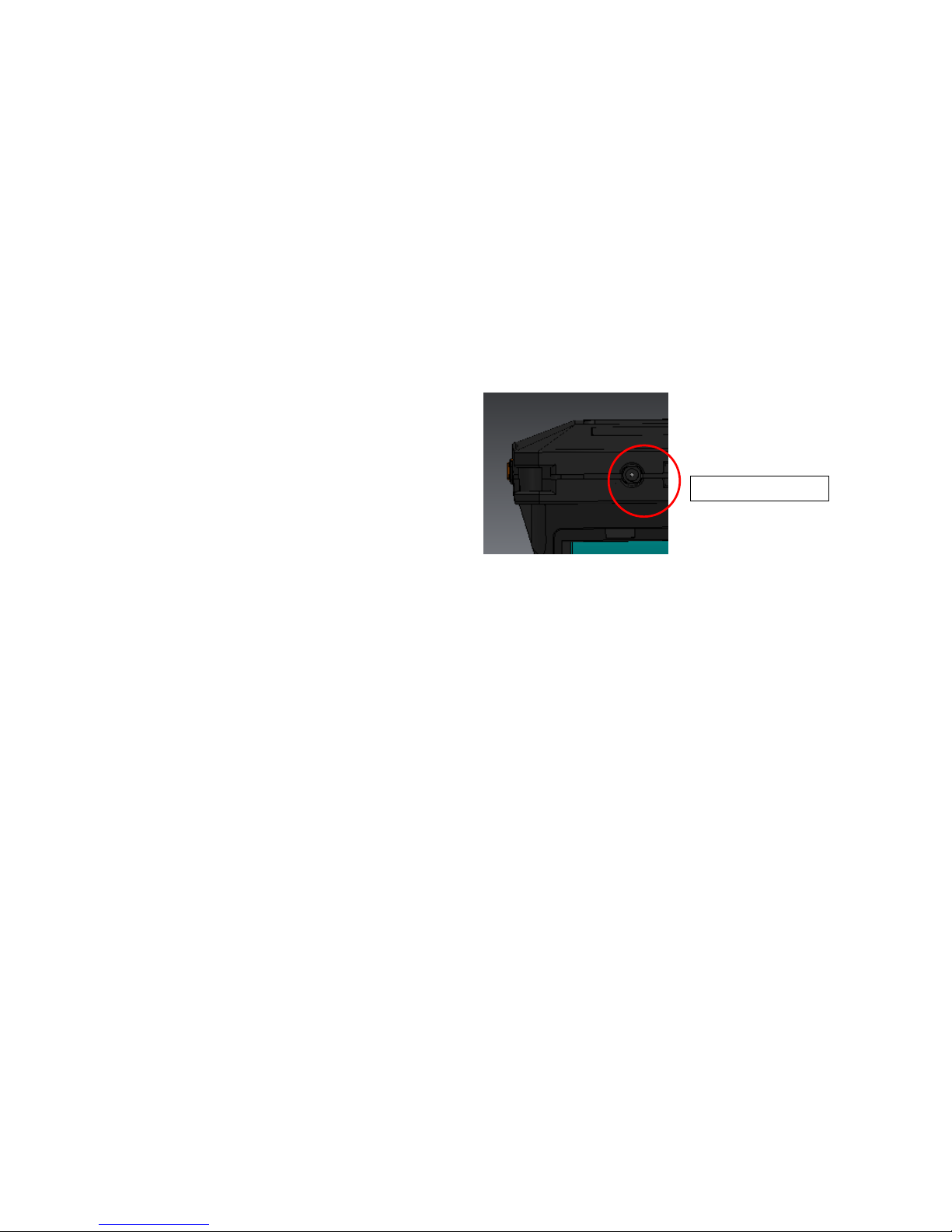
3. Measurement
Fig 1
DC OUT:
DC output of measurement data.
LCD Panel:
Touch panel display.
Function Button
(R):
Displays the setting screen, range screen
during measurement, etc.
Function
Button
(L):
Starts/Stops measurement.
SD Card Slot:
Waveform data storage.
Power
Connector:
AC adopter is available. (Optional)
Backlight Switch
Power
Pickup Connector
AC OUT:
AC output of measurement data.
Hand Strap
Mount
6
3.1 Before Getting Started
(1) You can select the computing method for velocity, acceleration, and displacement. Refer to the
Chapter 4-2 for more details. Initial settings are as follows:
■Acceleration : rms
■Velocity : rms
■Displacement : EQP (Equivalent Peak)
★ If you are familiar with our VM-7000L, EQP setting for the displacement is highly recommended.
Since the measurement data with the VM-7000L is indicated in EQP, you may easily compare the
data with the same setting.
★ For measurement of the vibration severity, velocity setting needs to be “rms.”
(2) Check the polarity carefully, and set two (2) AA batteries in the battery box. (NiCd or Alkaline)
For the use with the AC adaptor, connect the AC adapter cable to the power connector in the
bottom of the device.
(3) Connect the pickup cable to the pickup connector.
Refer to the following chapters for measurement.
The pickup needs to touch the subject for measurement. For the method to fix the pickup, refer to
the page 30.
(4) Language Setting
You can select Japanese or English to be displayed on the screen. Refer to the Chapter 4-9 for
details.
Power Connector
+ +
7
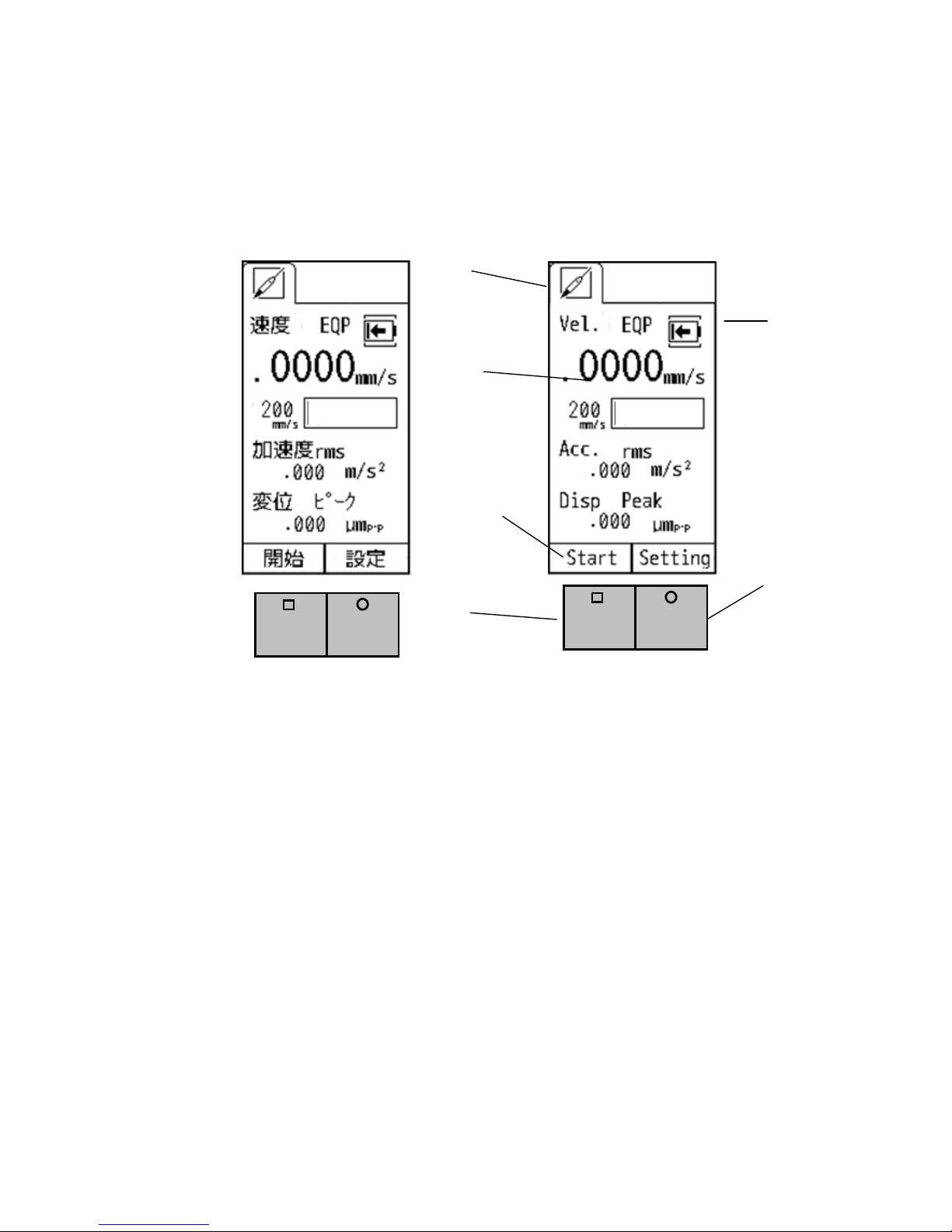
3-2. Measurement Screen
Turn on the SmartVibro by sliding an orange switch on the left side of the device. Initial screen
(Fig 2) will appear.
You can operate the device by using the touch screen and two function buttons.
Japanese English
Fig 2 Initial Screen
(1) Standard Measurement Mode
You can measure the OA value of acceleration in this mode.
(2) Measurement Range Bar
This shows the level of measurement data. The data is not absolute, but rough indication.
(3) Function Indicator
Valid functions are indicated. In the Fig 2, “Start” and “Setting” are operative.
(4) Function Button (L)
In the measurement mode, you can start or hold measurement when you press this button. In the
setting mode, you can check the battery level. (Chapter 4)
(5) Function Button (R)
In the measurement mode, range display will appear when you press this button. In the FFT mode
(available only with the VM-3024H), this button would switch the display from detailed to simple
indication of the result, and vice versa. (Chapter 5) As for the range setting, refer to the Chapter 4.
(6) Battery Indicator
This appears when the battery level is low.
(7) FFT
FFT mode starts when this tab is activated. (Chapter 5-1)
(8) Data Save
Data save mode starts when this tab is activated. Waveform will be stored in the SD card as plain
text. (Chapter 5-2)
(4) (6) (1) (2) (3)
8
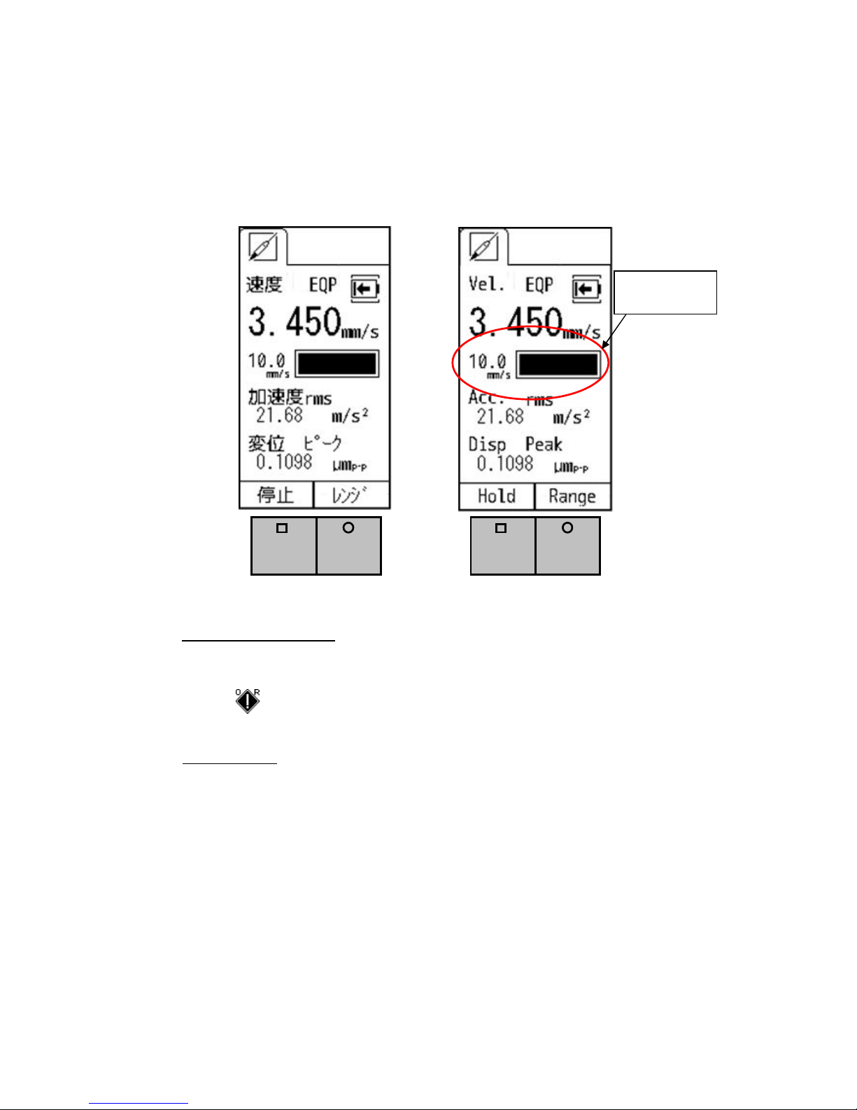
3-3. Operations during Measurement
Touching “Start” on the touch screen or press the function button L in the Figure 2 would start
measurement. The screen displays measurement status. (Fig 3)
Once you press the same function button or touch the “Hold” on the touch screen would hold
measurement and the display.
Japanese English
Fig 3 Display during Measurement
How to Change the Range
When the Auto Range function is OFF (as described in Chapter 4), the range key will be activated
during measurement. (Fig 3) Touching “Range” on the touch screen or pressing the function button
R will show the range setting display. You may adjust the range accordingly.
The icon, , will appear on the upper right corner of the screen when the value is over the range.
(Fig 4)
How to Zoom In
Touch the range bar area on the screen to zoom in the image. To zoom out, touch the same area
again. (Fig 5)
Touch here
to
zoom in.
 Loading...