

IMV CORPORATION VM-4424S, VM-4424H Instruction Manual

INSTRUCTION MANUAL
Portable Vibrometer: VM-4424S/H
IMV CORPORATION
Document Number TVE-6-3791
I s s u a n c e D a t e
April 9, 2012
V e r s i o n 1.0.3
Pages (Incl. Cover) 35

Revision History
Date Rev Details
Mar 03, 2012 1.0.0 New Issue
Mar 22, 2012 1.0.1
Corrected Figures and phrases.
Added optional accessories.
Apr 09, 2012 1.0.2
Added Preparation(3-1)
Added Definitions(10), including H-func
August 07, 2012
1.0.3 Added Title for BRG and H-func

目 次
1. Introduction .................................................................................................................................1
1-1. Panel Description ..................................................................................................................2
1-2. Package Contents..................................................................................................................3
2. Outline .........................................................................................................................................4
2-1. SmartVibro ............................................................................................................................4
2-2 Features .................................................................................................................................4
3. Measurement ...............................................................................................................................5
3.1 Before Getting Started............................................................................................................6
3-2. Measurement Screen .............................................................................................................7
3-3. Operations during Measurement ...........................................................................................8
4. Setting........................................................................................................................................10
4-1. Mode Setting .......................................................................................................................11
4-2. Calculation Setting ..............................................................................................................12
4-3. Filter ....................................................................................................................................14
4-4. Auto Range..........................................................................................................................15
4-5. Coupling of the H-Function .................................................................................................15
4-6. Sensitivity Setting of AC and DC Output .............................................................................16
4-7. Digital Volume .....................................................................................................................18
4-8. Battery Setting ....................................................................................................................18
4-9. Auto Power OFF ..................................................................................................................19
4-10. Contrast.............................................................................................................................19
4-11. Language Setting ..............................................................................................................19
4-12. Version Information...........................................................................................................20
4-13. Battery Indicator ...............................................................................................................21
5. The High-End Model; VM-4424H ................................................................................................22
5-1. FFT ......................................................................................................................................22
5-1-1. FFT Indication ..............................................................................................................22
5-1-2. FFT Setting ...................................................................................................................23
5-2 Waveform Save ....................................................................................................................24
5-2-1. Waveform Data Save ....................................................................................................24
5-2-2. Data Save Settings .......................................................................................................27
6. Specif ications .............................................................................................................................28
6-1. SmartVibro ..........................................................................................................................28
6-2. Pickup..................................................................................................................................28
7. Troubleshooting .......................................................................................................................29
8. Precautions ................................................................................................................................29
9. How to Fix the Pickup and Frequency........................................................................................30
10. Definitions ................................................................................................................................31

1
1. Introduction
We truly appreciate your purchase.
Please read this manual carefully before use and follow the cautions below for your safety.
Should you have any inquiries or find a problem during use, please consult our sales office near you or IMV
quality assurance department.
1. If the subject of the measurement could be hot, rotating, or near the movable
parts, assure the safety and fix the pickup for measurement.
Do NOT hold the pickup manually in these cases to avoid any possible accidents;
including burning yourself, and entangled cables.
2. Follow the instructions printed on the battery for replacement and disposal of used
batteries. Pay attention to the polarity of the battery for installation.
CAUTION

2
1-1. Panel Description
VM-4424 is available in Standard Model or High-End Model. Icons appeared on the display are different
in each model. High-end model has these two icons, , when the machine is turned on.
Standard Model
Japanese English
High-End Model
Japanese English
In this manual, panel displays of the standard model, VM-4424S, will be used to explain basic operation in
Chapter 3. Additional functions of the high-end model, VM-4424H, will follow in Chapter 5.

3
1-2. Package Contents
Product and Accessories for the VM-4424S/H
(1) Standard Product and Accessories
Products Qty Model Note Figure
Main Unit
SmartVibro 1 VM-4424S/H
Pickup 1 VP-4416 Piezoelectric Type
Probe 1
-
Handheld probe (with a
nut).
Φ6mm x 195mm
Output Cable 1
-
1.5m cable with a plug at
one end.
For output to a stroboscope
or recorder, etc.
Battery 2
-
AA Alkaline batteries
Instruction Manual
1
-
With inspection report
Accessories
SD Card 1
-
VM-4424H only
(2) Optional Accessories
Products Qty Note Figure
1
Long Pickup Cable
CE-3004-3 (3m)
CE-3004-6 (6m)
CE-3004-10 (10m)
To keep a distance from
the subject of
measurement.
(Example)
2
Magnet MH-201R
To fix the pickup on the
subject of measurement.
3
Cover PC-3024 Silicone jacket
4
AC Adapter PS-3024-S AC100-240V
5
Carrying Case C-3024
To store the SmartVibro
and pickup.
Specifications and appearances of the items above are subject to change without notice.

4
2. Outline
2-1. SmartVibro
SmartVibro is an acceleration meter placing emphasis on analysis, which is equipped with functions of
H-function measurement, i.e., envelope processing. This machine serves various uses in measurement
including checking the machines and equipment from various points of view. With SmartVibro, you can not
only analyze the bearing, but also measure the acceleration amount and check fluctuation components in
low-speed rotating machinery bearings.
2-2 Features
■Analysis Capability
RMS value of acceleration and H-function measurement enables precise data gathering that benefits
your decision-making process.
■Simultaneous Measurement
High-speed processing CPU enabled simultaneous display of acceleration, velocity and displacement of
velocity signal coming from the sensor.
■LCD Screen
Various settings like measurement conditions are possible by a touch panel.
■FFT Analysis Function (VM-4424H Only)
Real-time FFT analysis is possible with a minimum condition setting to check vibration frequency
components.
■Waveform Data Save (VM-4424H Only)
Waveform can be stored.
Stored data in the SD card can be exported to a personal computer.
■Language
SmartVibro can be operated in Japanese or English by changing the setting.
■Volume Control
Volume is controllable with the digital volume.

5
3. Measurement
Fig.1
DC OUT:
DC output of measurement data.。
LCD Panel:
Touch panel display.
Function Button
(R):
Displays the setting screen, range screen
during measurement, etc.
Function
Button
(L):
Starts/Stops measurement.
SD Card Slot:
Waveform data storage.
(Only with VM-4424H)
Power
Connector:
AC adopter is available. (Optional)
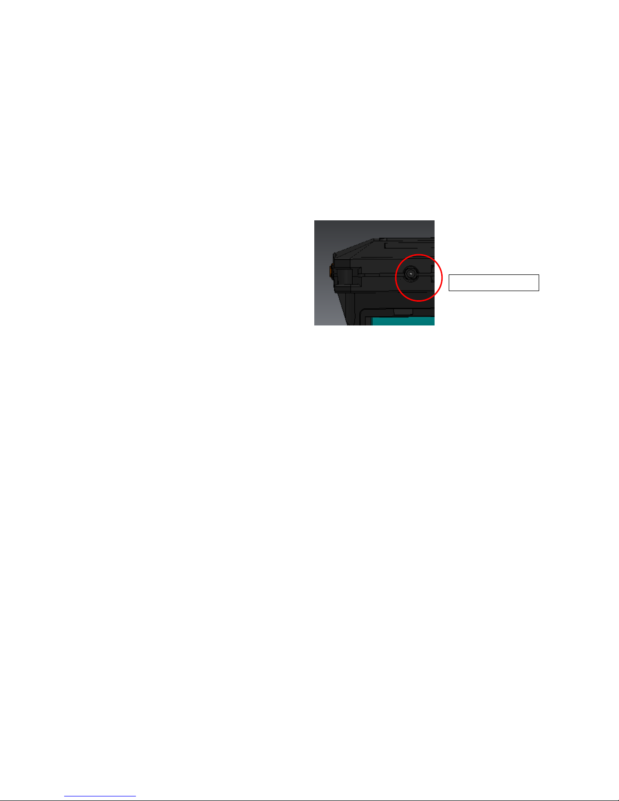
Backlight Switch
Power
Pickup Connector
AC OUT:
AC output of measurement data.
6
3.1 Before Getting Started
(1) You can select the computing method for velocity, acceleration, and displacement. Refer to the
Chapter 4-2 for more details. Initial settings are as follows:
■Acceleration : rms
■Velocity : rms
■Displacement : EQP (Equivalent Peak)
(2) Check the polarity carefully, and set two (2) AA batteries in the battery box. (NiCd or Alkaline)
For the use with the AC adaptor, connect the AC adapter cable to the power connector in the
bottom of the device.
(3) Connect the pickup cable to the pickup connector.
Refer to the following chapters for measurement.
The pickup needs to touch the subject for measurement.
★For the method to fix the pickup, refer to the page 25.
(4) Language Setting
You can select Japanese or English to be displayed on the screen. Refer to the Chapter 4-9 for
details.
Power Connector
+ +
7
3-2. Measurement Screen
Turn on the SmartVibro by sliding an orange switch on the left side of the device. Initial screen (Fig
2) will appear.
You can operate the device by using the touch screen and two function buttons.
Japanese English
Fig 2 Initial Screen
(1) Standard Measurement Mode
VM-4424S is equipped with this mode only.
(2) Measurement Range Bar
This shows the level of measurement data. The data is not absolute, but rough indication.
(3) Function Indicator
Valid functions are indicated. In the Fig 2, “Start” and “Setting” are operative.
(4) Battery Indicator
This appears when the battery level is low.
(5) Function Button (L)
In the measurement mode, you can start or hold measurement when you press this button. In the
setting mode, you can check the battery level. (Chapter 4)
(6) Function Button (R)
In the measurement mode, range display will appear when you press this button. In the FFT mode
(available only with the VM-4424H), this button would switch the display from detailed to simple
indication of the result, and vice versa. (Chapter 5) As for the range setting, refer to the Chapter 4.
(4) (6) (1) (2) (3) (5)
8
3-3. Operations during Measurement
When the device is not measuring, “Start” is shown in the function indicator on the screen. (Fig 2)
Pressing the function button L would start measurement. The screen displays measurement status.
(Fig 3)
Once you press the same function button or touch the “Hold” on the touch screen would hold
measurement and display the result at that point.
Japanese English
Fig 3 Display during Measurement
How to Change the Range
When the Auto Range function is OFF (as described in Chapter 4), the range key will be activated
during measurement. (Fig 3) Touching “Range” on the touch screen or pressing the function button
R will show the range setting display. You may adjust the range accordingly.
The icon, , will appear on the upper right corner of the screen when the value is over the range.
(Fig 4)
How to Zoom In
Touch the range bar area on the screen to zoom in the image. To zoom out, touch the same area
again. (Fig 5)
Touch here
to
zoom in.
 Loading...