

PowerLED Downlight
Installation and Operation Manual
Sardinia Cyprus
Cyprus
Eyeball
OVERVIEW
The Sardinia and Cyprus are energy saving flush-mount spots
that directly replace power-hungry 120V-35W halogen spots
commonly found on large vessels and megayachts. Both feature
integrated current-regulated drive electronics that accept
120VAC line-voltage; greatly simplifying electrical hook-up and
eliminating the need for external drivers, LED converters, or stepdown transformers required by mainstream LED and halogen
products.
The fixed direction models may be either screw mounted
or secured with the springs provided. The Cyprus Eyeball
model mounts with springs only. An 18” long triplex cable is
provided for connection to a junction box or use the optional
bracket with Molex™ connector (included with each unit). The
Sardinia and Cyprus’ thermal management system includes
efficient heat sink design and thermal compensator that powers
down the unit in the event of high ambient heat conditions or
overheating. Emitting no radiated heat, these fixtures will keep
cabin temperatures comfortable and eliminate risk of burning or
scorching, long associated with hot halogen bulbs. Finally, our
use of high quality LEDs and custom-built solid state electronics
contributes to long fixture life, eliminating the cost associated
with changing delicate bulbs.
- 1 -
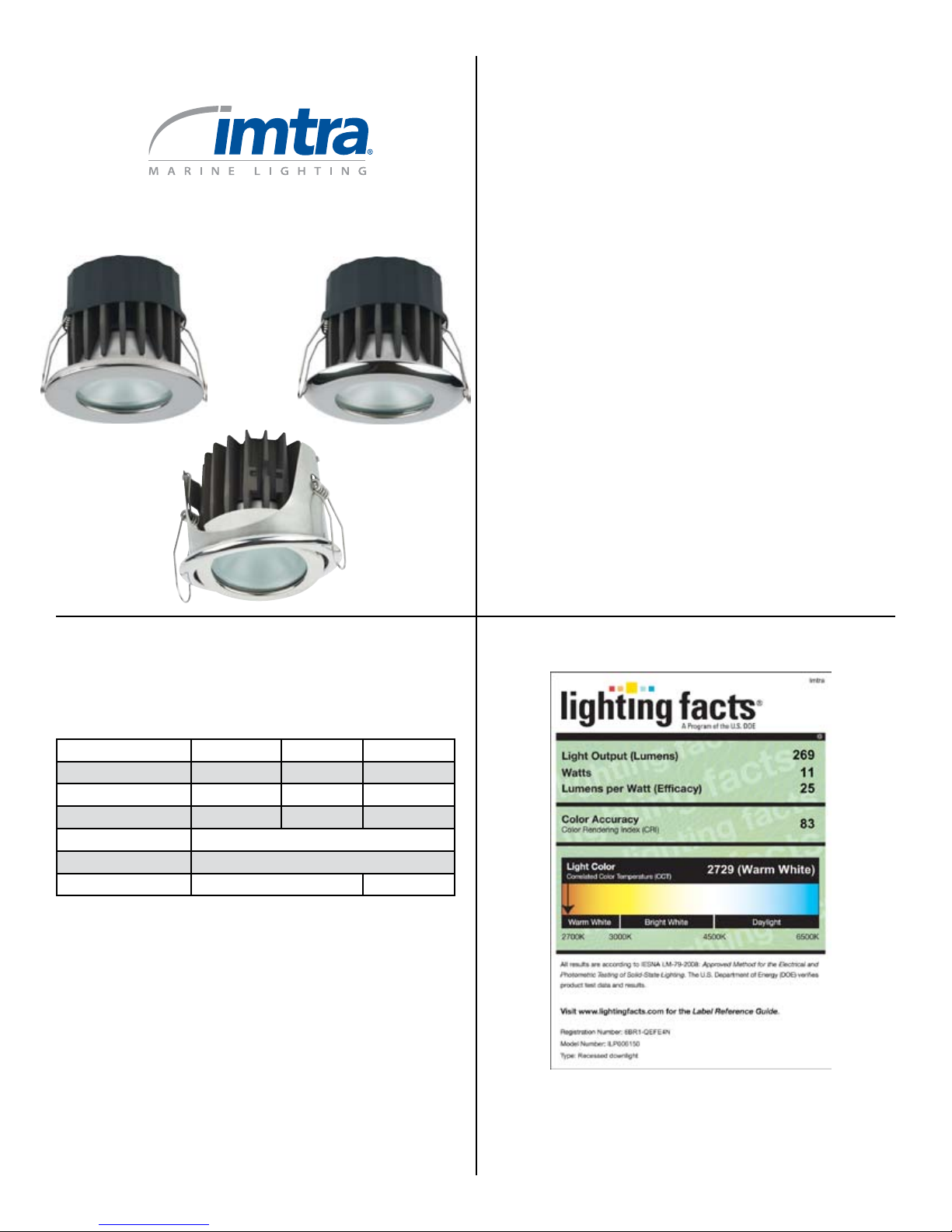
SPECIFICATIONS
Sardinia Cyprus
Trim Ring Diameter 3.76” (96mm) 3.76” (96mm) 3.79” (96mm)
Trim Ring Height 0.27” (7mm) 0.27” (7mm) 0.25” (6.25mm)
Recess Cutout Diameter 2.89” (73mm) 2.89” (73mm) 3.38” (85.7mm)
Recess Depth 2.81” (71mm) 2.81” (71mm) 2.86” (72.7mm)
Input Voltage Range 90-135 VAC
Power Consumption 10.5 Watts
IP Rating IP65* IP40**
* IP65: “Protected from the ingress of dust and low pressure jets of water from all directions”
**IP40: “Protected against solid objects down to 1mm. No protection against direct sprays of
This rating does not apply to the rear of the fixtures.
water.”
- 2 - - 3 -
Cyprus
Eyeball
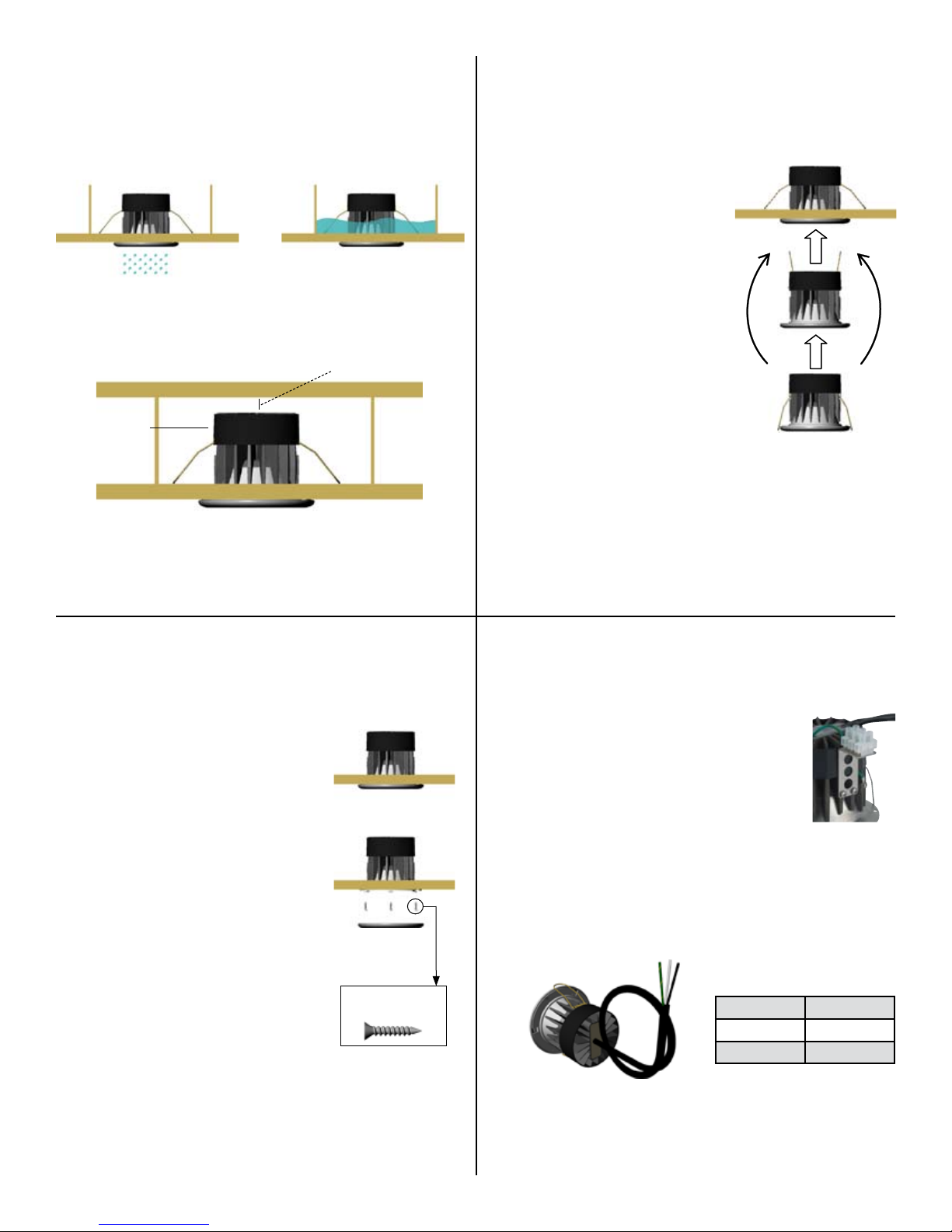
PHYSICAL INSTALLATION
It is imperative that the lights are mounted in such a location that
the fixtures are protected from the rear against water exposure.
IP65 models only
Also, it is important that the lights are mounted with airspace
around the heat sink housing to allow for convective cooling
of the lights. We recommend a distance of ½” (13mm) of free
space above the housing.
Resonance suppression
band (do not remove)
IP40 & IP65 models
½” (13mm)
Spring Mount Installation Instructions
1. A. For Sardinia/Cyprus fixed
direction models: Cut a 2 7/8”
(73mm) diameter circle in the
mounting surface.
B. For Cyprus Eyeball: Cut
a 3 3/8” (85mm) circle in the
mounting surface, Note: the hole
must not be any larger than this.
2. Connect the light to an AC power
source following the Wiring
Instructions in the next section of
this guide.
3. Once all electrical connections are
made and secure, gently bend
back the mounting springs of your
PowerLED and insert the spring
tips into the cutout circle in the
mounting surface (see Figure 1).
Figure 1
- 4 -
Screw Mount Installation Instructions
1. For Sardinia/Cyprus fixed direction
fixtures: Cut a 2 7/8” (73mm) diameter
circle in the mounting surface.
2. Connect the light to an AC power
source following the Wiring
Instructions in the next section of this
guide.
3. Once all electrical connections
are made and secure, insert your
PowerLED into the cutout circle and
fasten with #4 flat head screws (see
Figure 2).
4. Place the trim ring over the light
making sure the tabs of the housing
engage the openings of the trim ring.
Twist the trim ring on to secure it.
Figure 2
Use #4 at head
screws only
- 5 -
WIRING INSTRUCTIONS
1. Wiring connections shall be made within
the necessary enclosures (junction boxes) as
required by any applicable standards, codes
or laws. The available bracket and MolexTM
connector may be used where appropriate.
Otherwise, 18” of triplex cable is provided to
allow proper wire routing to a suitable location.
2. Connect the light to an AC power source by connecting the
white wire to neutral, the black wire to live and the green/
yellow wire to ground.
3. If a dimmer is used, the black wire should be connected to the
terminal or wire labeled “LOAD” on the dimmer.
4. Please refer to wiring diagrams and dimmer compatibility
chart on pages 8-11.
Wire Function
Black Live
White Neutral
Green/Yellow Ground
- 6 - - 7 -

Wiring Diagram - One Way Switching
No Dimming•
Single Switch Location•
Wiring Diagram - Three Way Switching
No Dimming•
Multiple Switch Location•
1-Way Switch
1P/1T - On/Off
Live
90-135VAC
Neutral
Ground
Wiring Diagram - Dimming
With Dimming•
Live
90-135VAC
Neutral
Ground
- 8 -
Sardinia or
Cyprus
Sardinia or
Cyprus
Sardinia or
Cyprus
Sardinia or
Cyprus
Sardinia or
3-Way Switch
1P/1T - On/On
3-Way Switch
1P/1T - On/On
Cyprus
Sardinia or
Cyprus
Live
90-135VAC
Neutral
Ground
- 9 -
DIMMER COMPATIBILITY CHART
The Sardinia and Cyprus light fixtures are designed to operate with
most Electronic Low Voltage, Phase Control dimmers. Below is a list of
dimmers that have been tested and approved by Imtra.
Brand Model
Lutron® Skylark® SELV-300P
Lutron® Nova® NELV 450
Lutron® Maestro® MAELV-600-IV
Lutron® Nova T® NTELV-600
Lutron® Grafik Eye® w/Diva® Control PHPM-WBX w/DVF-103P
Lutron® Panel Module HW/LP-RPM-4A-120
Lutron® RadioRA RRD-6NA
Crestron® DIN-1DIMU4
Crestron® CLX-1DELV4
Crestron® CLS-EXP-DIMU
- 10 -
- 11 -

LIMITED WARRANTY
Imtra warrants the light-emitting LSA (LED spotlight assembly)
component of our IML PowerLED spot lights & fixtures for 5 years
from the date of purchase. If the LSA should cease to function within
5 years, return the complete spot light assembly to Imtra for repair or
replacement.
This warranty does not apply to damage resulting from actions of the
user such as misuse, improper wiring/installation, operation outside of
specification, improper maintenance or repair, unauthorized modification,
lightning strike or damage from a power surge.
The trim ring (bezel) of the IML Power LED spot lights are warranted for
either two years (stainless steel or powder coated) or one year (gold or
satin-nickel) depending on the finish of the fixture.
Imtra specifically disclaims any implied warranties, merchantability or
fitness for a specific purpose and will not be liable for any direct, indirect,
incidental or consequential damages. Imtra’s total liability is limited to
repair or replacement of the product.
The warranty set forth above is inclusive and no other warranty, whether
written or oral, is expressed or implied.
If it should become necessary to return a fixture for service during or
beyond the warranty period, please refer to Imtra’s standard Return Policy
as detailed on Imtra’s website (www.imtra.com) or call Imtra customer
service at (508) 995-7000.
No returns are accepted without a Return Authorization (RA) number.
- 12 -
30 Samuel Barnet Boulevard, New Bedford, MA 02745
(508)995-7000•www.imtra.com
 Loading...