

IMTH.de SST1 Installation Manual And User's Manual
IMT Innovative Modell Technik Hamburg SST1 (Version 3.0 engl.) Page 1 / 16
Installation guide and users-manual of the Pod- and Schottelsteering
SST1

IMT Innovative Modell Technik Hamburg SST1 (Version 3.0 engl.) Page 2 / 16
Thank you very much for choosing our Pod- and Schottelsteering SST1.
Please read the entire user’s manual carefully prior installing and using the device.
This user’s manual contains important safety instructions, detailed information about fitting,
parameterization and operation of the SST1 steering.
You will recognize even the steps are complicate in reading will work out pretty simple as we have
concentrated on practicality during engineering.
If you face any additional question about the initial installation, the parameterization or the operation
please view our videos at www.imth.de or contact us.
This user’s manual is part of the product. Please keep it safely and in case of forwarding the product to
a third party, please make sure the user´s manual goes with it.
Any non-observance of this user manual or the safety regulations will result in void of warranty.
Continuous improvement is driving our work. Therefore scope of delivery in form, function, design and
technical ability might be subject of change.
Please be aware that no claims can be derived out of any pictures, given information, descriptions and
drawings.
Delivery contents:
1 x user manual
1 x PCB SST1 (Basic or Extended)
1 x disc Magnet
Safety:
The SST1 PCB is designed to operate in models of ships and is only allowed to be used in that way.
Use this device only within the given specification (see table of specification).
Store and use the SST1 steering only in a dry environment.
Any mechanical- or electrical change to the steering or exceed of the specification will result in
immediate loss of any warranty against the manufacturer.
Any damage to the guarantee seal on the bottom result in immediate loss of warranty also.
Swallowing a magnet can lead to life-menacing complications, in particular if more than one magnet
was swallowed. In this case contact immediately a doctor.
Pay special attention of running in “Master-Slave” mode is more unsafe. You should only operate this
mode in a safe environment. More details are under “Master-Slave Mode” at page 11 of this manual.
Check the correct operation and function of the steering out of the water prior any ride.
Specification:
Voltage: 5,5 - 10,0 V
Operating Power: ca. 30 mA at 6,0 V
Max. Power: 1,0 A
Impulse In: < 5,5 V
Impulse Out: ca. 5,0 V
Weight: ca. 15g
Size (BxTxH): 80 x 40 x 12 mm
Operating Temperature: 0 - 40 oC
Demanding Channels: 2

IMT Innovative Modell Technik Hamburg SST1 (Version 3.0 engl.) Page 3 / 16
Introduction:
Different ways of steering are common in navigation. Also one is named Pod-propulsion and offered
by different manufacturers.
All of them have one thing common: The Pods are able to run a full circle with no limit in turn.
As the direction to move the propeller keeps always the same, you only achieve a change of direction
by turning the propeller half a circle.
The benefits of such engines are not only the ability in exact maneuvering.
The available Servos and remote controls are not able to provide such realistic steering, because the
Servos are limited with no endless turn.
You overcome this boundary with your SST1 steering first time. Maneuvering your model ship
absolutely as real is now possible with standard model components.
After fitting the SST1 and accompanying mechanical and electrical adjustments, you need to align the
SST1 to your remote control and pod. This parameterization only need to be done once, as all settings
will be saved. The settings are available to upload at next restart.
Basic requirements to use the SST1:
To enable your ship for realistic steering with the SST1 your model needs to provide following two
basic properties:
1.) Your pods can show a 360° electrical turn without the given turn limit.
You have two options to achieve this requirement:
You choose a Servo (Graupner C 5191 / Art.-No. 5133) and remove the turn limitation. Doing
so you achieve a single unit including speed control, engine and gear in one housing.
A speed control directs an engine in both directions. This engine is linked to a gear and
achieves an alternative turn of the pod (Standstill by ca. 1,5 ms).
The recommended the Servo option, to simply remove the turn limitation and keep using the
professionally built combination of speed control, engine and gear is shown in an example video on
www.imth.de.
2.) The actual position of the pod needs to be recorded by a sensor, which is directly on the SST1
board.
The sensor uses a magnet to record the position of the pod without touching it. The magnet moves
analogously to the pod above the sensor and must rotate centrically above the sensor.
If the pod carries a full circle the magnet needs to do the same!
Right now it is uncritical if the direction of both turns are synchronic or opposite. Important is the
analogy of the two turns to provide a 1:1 exact balance of magnet to pod.

IMT Innovative Modell Technik Hamburg SST1 (Version 3.0 engl.) Page 4 / 16
Mechanical Installation:
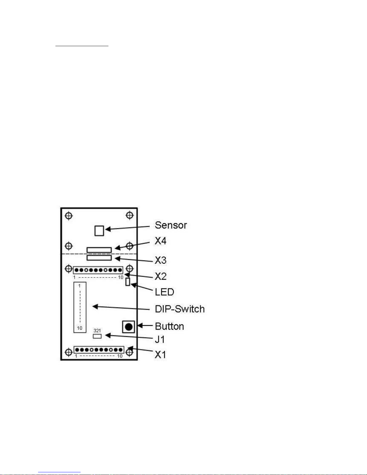
As you already read the revolving magnet needs to be installed above the sensor.
The sensor is located in the middle of the SST1 in the smaller part of the pcb, which is separated from
the main part by the dotted line.
The magnet needs to be installed centered above the sensor with a distance of 0.5 to 1.5mm.
For your easier installation we have provided 4 holes around the sensor. The sensor is installed in the
center of these 4 holes. For further easy identification you will find a cross on the backside of the pcb,
which also identifies the center.
As better you place the magnet as more accurate the sensor will recognize the angle of the pod and
more exact you can run it.
If the SST1 dimensions are too big, you might separate the sensor part from the main pcb at this
dotted line and reconnect the two parts with 5 wires.
Connection 1 to connection 1 and so force of the row X3 and X4. The connection shouldn´t be longer
than 10 cm.
Attention: You will lose the warranty carrying out this action.
Of course we will service you if needed also in this case.
IMT Innovative Modell Technik Hamburg SST1 (Version 3.0 engl.) Page 5 / 16
Electrical Installation:
For a safe use the pcb needs unshielded DC of 5.5 – 10.0 Volts, which have to be connected to the
headers X1 and X2
Pay attention that all (+) connections within the SST1 are connected with each other as well as all
(-) connections.
With a DC of 5.5 to 10.0 Volts you should be able to connect the servo and the speed control to the
header X2 directly only if the power carries less than 1.0 Ampere. Pay attention to the max operating
Power.
In the case the DC is higher 6.0 V, normally most servos are not capable. In this case you have to
disconnect the (+) to the servo or the speed control and reconnect to a suitable power support.
On the pulse inputs it is allowed to have max 5V only. This will normally be the case if you have a
direct connection from the receiver to the SST1.
You can run the SST1 with 5V also. To do so, you have to place a solder bridge und cut a small trace.
Attention: Following the modification some safety precautions will be overridden and you will lose the
warranty.
Best if you use a BEC module providing 5.5 V to run the steering in this case. In any case the
operating power exceeds 5.5 V the steering will be destroyed.
If you still want to modify, cut the existing bridge at J1 between 2 +3 and solder a new fine bridge from
1 to 2.
 Loading...