

Imtex-Controls SLR Series, SLR16 Series, SLR14 Series, SLR17 Series Installation & Adjusting Instructions
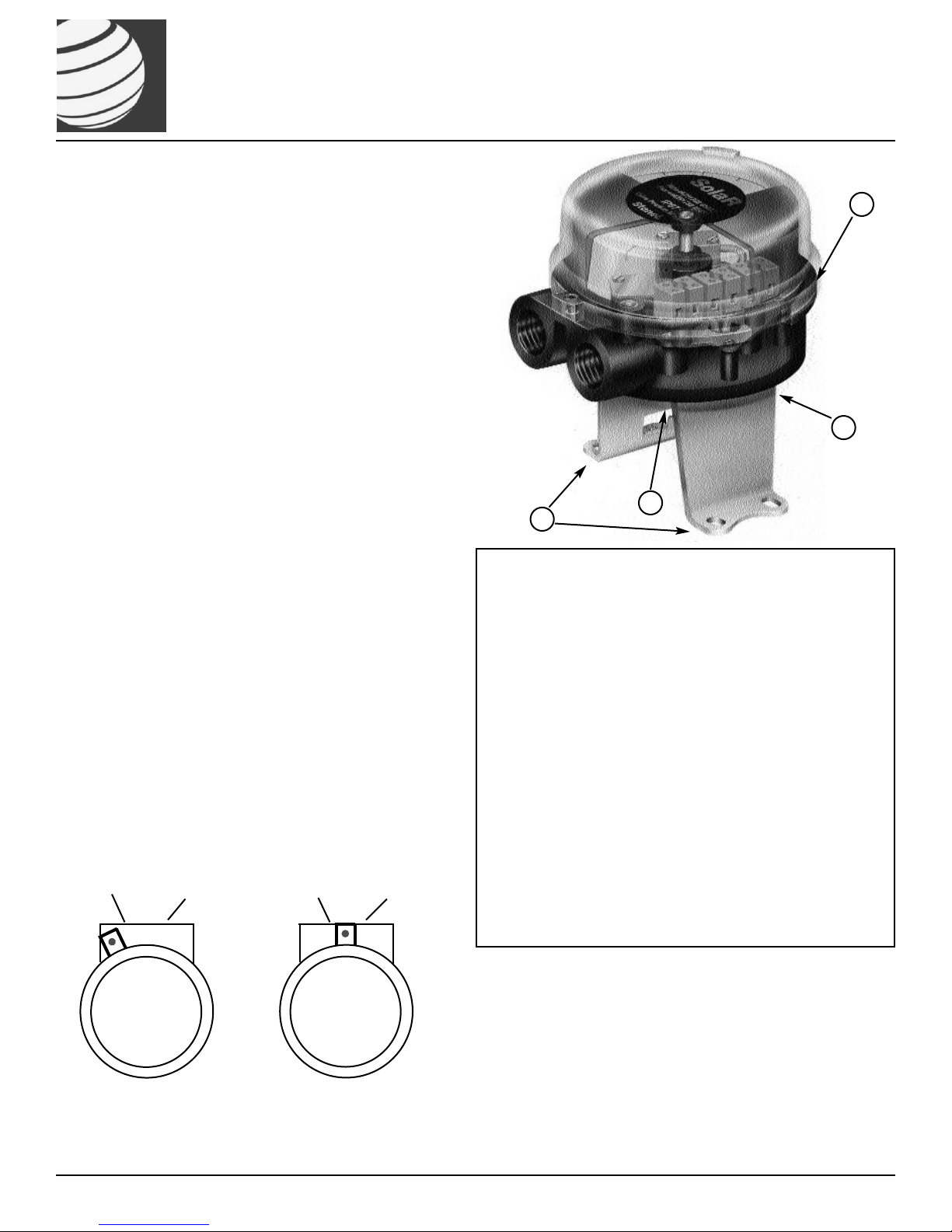
Mounting to Namur Style Actuator
1. Attach mounting plate to monitor using fasteners and
lockwashers provided.
2. Align namur shaft so that it fits in the groove on the top of the
actuator shaft.
3. Attach mounting plate to actuator using fasteners and
lockwashers provided.
4. Operate actuator to full open and full closed positions to
check for proper coupling alignment. Eccentricity of shaft
must be no greater than 1/4 mm from centerline. Adjust if
necessary and snug-down adjustment bolts tightly.
Mounting to Non-Namur Actuator
1. Attach mounting plate to monitor using fasteners and
lockwashers provided.
2. Remove spacer screw and attach spring torque coupler or
drive block to the shaft with spacer screw or screw provided
with mounting kit. Align drive block or spring torque coupler
with mating shaft and lower until the mounting bracket meets
its mating surface. Ensure the coupler or drive block have
fully engaged the output shaft of the device to be monitored.
3. Attach mounting plate to actuator using fasteners and
lockwashers provided.
4. Operate actuator to full open and full closed positions to
check for proper coupling alignment. Eccentricity of shaft
must be no greater than 1/4 mm from centerline. Adjust if
necessary and snug-down adjustment bolts tightly.
Visual Indicator Adjustment
5. Remove cover from unit. Lift indicator drum to disengage
from splined drive. Rotate indicator until it reaches the
desired position. Slide indicator drum onto splined drive to reengage. Replace the cover.
Touch & Tune Switch Setting
6. Lift bottom cam and rotate until switch is activated.
Release cam and be sure it slides fully onto spline.
6a. Operate actuator to opposite position, push down on top cam
and repeat process.
1
3
2
5
Type SLR with Mechanical Switches
(SLR14_ _ _, SLR16_ _ _, SLR17_ _ _)
Installation & Adjusting Instructions
Publ #105097revUKA
IMTEX Controls Ltd.
Unit 5a Valley Industries
Hadlow Road
Tonbridge, Kent, TN11 0AH
UK
Tel : +44(0)1732 850360
Fax : +44(0)1732 852133
E-mail: sales@imtex-controls.com
Website: www.imtex-controls.com
Installing & Removing Cover
(Refer to Diagram 1 and 2 below)
The cover goes from open to full closed with a turn of about 25 degrees.
Removing the Cover
I. Loosen cover lock screw to where the bottom of the screw head is
flush with top of the cover locking tab. This is the non-locking positon
and the way it is shipped from the factory.
II. Remove the cover by turning it approximately 25 degrees
counterclockwise until it hits the stop and lift the cover off.
Replacing the Cover
I. The cover O’Ring must be in place on the housing body.
II. Place the cover on the housing with the cover locking tab 25 degrees
counterclockwise from the hole between the conduit entries (see
diagram 1). The cover will fit properly on the housing only in this
position.
III. Twist the cover 25 degrees clockwise until the cover locking screw is
directly over the hole between the conduit entries (see diagram 2).
IV. To insure the IP67 enclosure rating the cover must be completely
closed and the O’Ring sealed to keep out water. This is acheived
when the cover is closed and locking screw can be easily screwed in
until the top of the screw head is flush with the top of the cover
locking tab. Check the cover O’Ring to make sure it is in place and
not buckled.
No Changes Authorised Without Prior Approval from IMTEX.
Conduit Entries Conduit Entries
Cover Open Position Diagram 1 Cover Closed Diagram 2
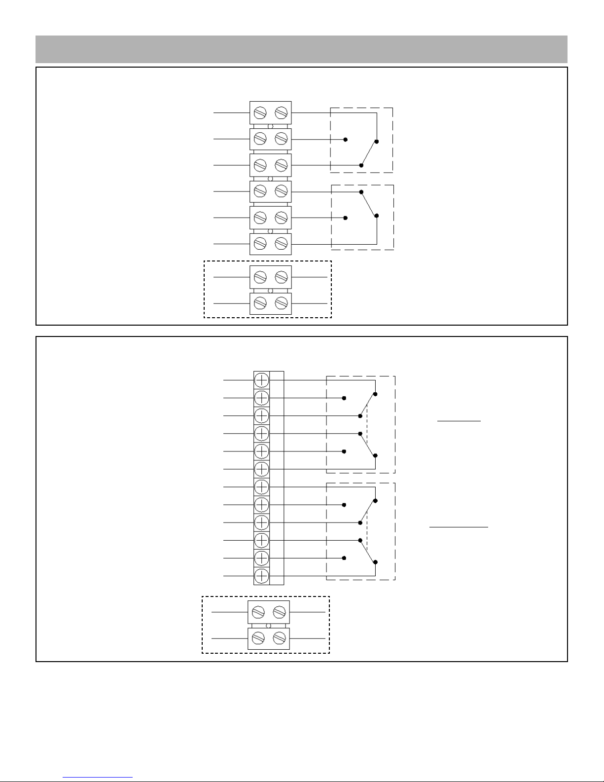
Wiring Diagrams
Publ #105097revUKA
Page 2
IMTEX Controls Ltd Tel : +44(0)1732 850360 · Fax : +44(0)1732 852133 · Website: www.imtex-controls.com
Electrical Ratings
SLR16_ _ _: 10 Amps @ 125/250 VAC
SLR17_ _ _: 0.5 Amps @ 30 VDC
2 SPDT Switches (SLR16___, SLR17___)
2 DPDT Switches (SLR14___)
Electrical Ratings
SLR14_ _ _: 4.5 Amps @ 125/250 VAC
SOL 1
SOL 2
SOL PWR 1
SOL PWR 2
SOL 1
SOL 2
SOL PWR 1
SOL PWR 2
TOP NC1
TOP NO1
TOP C1
TOP C2
TOP NO2
TOP NC2
BTM NC1
BTM NO1
BTM C1
BTM C2
BTM NC2
BTM NO2
TOP SWITCH
(Individual Elements Actuate
with Common Plunger)
BOTTOM SWITCH
(Individual Elements Actuate
with Common Plunger)
Additional 2-Pole Terminal Block
Provided in Unit
Additional 2-Pole Terminal Block
Provided in Unit
BTM NC
BTM NO
BTM C
TOP NC
TOP NO
TOP C
BOTTOM SWITCH
TOP SWITCH
 Loading...