

Page 1

TurboCAD
Version 11
REFERENCE MANUAL
IMSI US
100 Rowland Blvd.
Novato. CA 94945, USA
Tel: +1-415-878-4000
Fax: +1-415-897-2544
Web Site
www.imsisoft.com
www.turbocad.com
®
The material presented in this publication is copyright-protected © 1986–2005 by IMSI and may not be reproduced
in any form, by any method for any purpose without the prior written consent of IMSI. Information in this document
is subject to change without notice. It is against the law to copy the software, except in accordance with the terms
of the licensing agreement.
Page 2

PROGRAM LICENSE AGREEMENT
IMPORTANT NOTICE: Please read the terms of the following License Agreement carefully. Your use of the product
signifies your acceptance of the terms of the Agreement. If you do not agree with the terms of this Agreement, you
should promptly return the package; your money will be refunded. Retain this License Agreement for future reference.
Article 1: License Grant
The software is the intellectual property of IMSI® and its licensors, and is protected by law, including United States copyright
laws and international treaties.
IMSI® grants to you a license:
1. To use the program on a single machine.
2. To make a single archival back-up copy of the program in support of your use of the single program on a single machine.
3. To modify the program and/or merge it into another program for use on a single machine.
4. To transfer the program to another party if that party agrees to accept the terms and conditions of this Agreement, and you
do not retain any copies of the program, whether in printed, machine-readable, modified, or merged form. Except as
expressly provided for in this license, you may not copy, modify, or transfer this program.
5. If the software in this package is licensed as a Site License, it is licensed for use on several machines. Additional master
copies of the software may be made by the licensee, equal to the number of licenses purchased.
No reverse engineering. Except as stated above, YOU MAY NOT MODIFY, TRANSLATE, DISASSEMBLE, OR
DECOMPILE THE SOFTWARE, OR ANY COPY, IN WHOLE OR PART.
Article 2: Term
The license is effective until terminated. You may terminate the license at any time by destroying the program together with
all copies, modifications, and merged portions in any form. The license will also terminate upon conditions set forth elsewhere
in this Agreement, and IMSI
termination for any reason, to destroy the program together with all copies, modifications, and merged portions in any form.
Article 3: Disclaimer of Warranties and Limitations of Remedies
®
1. IMSI
software is licensed to you As Is. You, the consumer, bear the entire risk relating to the quality and performance
of the software. In no event will IMSI® be liable for direct, indirect, incidental, or consequential damages resulting from
any defect in the software, even if IMSI
to have defects, you, and not IMSI®, assume the cost of any necessary service or repair. In the event any liability is
imposed on IMSI®, IMSI's liability to you or any third party shall not exceed the purchase price paid for this product.
2. Thirty-day limited warranty on disks. IMSI® warrants the enclosed disks to be free of defects in material and
workmanship under normal use for 30 days after purchase. During the 30-day period, you may return a defective disk to
IMSI® with proof of purchase, and it will be replaced without charge, unless the disk is damaged by accident or misuse.
Replacement of a disk is your sole remedy in the event of a defect. This warranty gives you specific legal rights, and you
may also have other rights which vary from state to state.
3. THE LIMITED WARRANTY STATED ABOVE IS THE ONLY WARRANTY OR REPRESENTATION OF ANY
KIND WITH RESPECT TO THE SOFTWARE MADE BY IMSI
CREATION, PRODUCTION, DELIVERY, OR LICENSING OF THE SOFTWARE. IMSI® AND ANY SUCH THIRD
PARTY DISCLAIM ALL WARRANTIES, EXPRESS OR IMPLIED, WITH RESPECT TO THE SOFTWARE, ITS
QUALITY, RELIABILITY OR PERFORMANCE; OR ITS MERCHANTABILITY, NON-INFRINGEMENT OF
THIRD PARTY RIGHTS, OR FITNESS FOR A PARTICULAR PURPOSE.
4. Some states do not allow the exclusion or limitation of implied warranties of liability for incidental or consequential
®
may terminate your license if you fail to comply with this Agreement. You agree, upon such
®
had reason to know of the possibility of such damage. If the software proves
®
OR ANY THIRD PARTY INVOLVED IN THE
Page 3

PROGRAM LICENSE AGREEMENT
damages, so the above limitations or exclusions may not apply to you.
Article 4. Product Serial Number and Required Activation:
Many of the software programs IMSI® produces contain a serial number and activation system designed to prevent unlicensed
or illegal use of the software. If this software contains such a system you agree that IMSI® may use these measures to protect
®
IMSI
against software piracy. Software using this system may contain technology that limits the ability to install and uninstall
the software on a computer to not more than a finite number of times for a finite number of computers. This License and the
software containing this technology require activation as further set forth in the Installation program of the software. The
software using this system will only operate for a finite period of time prior to software activation by you. During activation,
you will be asked to provide your unique product serial number provided with the software over the Internet to verify the
authenticity of the software. If you do not complete the activation within the finite period of time as prompted by the software,
the software will cease to function until activation is complete, which will restore software functionality. In the event that you
are not able to activate the software over the Internet, you may contact IMSI Customer Service via the telephone to complete
the activation process, using the information provided by IMSI
Article 5: General
1. You may not sub-license, assign, or transfer the license or the program except as expressly provided in this Agreement.
Any attempt otherwise to sub-license, assign, or transfer any of the rights, duties, or obligations hereunder is void.
2. This Agreement will be governed by the laws of the State of California, and you agree that any claims regarding the
software shall be brought in California, and waive any objections to jurisdiction in the US District Court for the Northern
District of California or the California Superior Court for Marin County.
3. You acknowledge that US laws prohibit the export/re-export of technical data of US origin, including software, and agree
that you will not export or re-export the software without the appropriate US and foreign government license.
®
during activation, or as may be set forth in the documentation.
Page 4

COPYRIGHT
TurboCAD, FloorPlan 3D and the IMSI logo are registered trademarks of IMSI.
TurboCAD Professional®, TurboCAD ® 1987-2005, IMSI. All rights reserved.
FloorPlan® 3D 1997-2001, IMSI. All rights reserved.
Spatial Technologies Copyright - ACIS© 1994-2005.
LightWorks Design Copyright - LightWorks© 1990-2005.
Microsoft Copyright - VBA© 1996-2004.
Corel OCR-TRACE Copyright (c) 1996 Corel Corporation.
ImageCELs® copyright© 1989-1999 IMAGETECTS, All Rights Reserved.
ImageCELs® is a registered trademark of IMAGETECTS.
The RealNet logo and technology are copyright 1998-2000 RealNet Software Productions, Inc.
Adobe, Acrobat, and the Acrobat logo are trademarks of Adobe Systems Incorporated, which may be registered in certain
jurisdictions.
Flash is a registered trademark of Macromedia.
Portions Copyright © 2005 by:
Arthur D. Applegate
OpenDWG Alliance
Lithonia Lighting
Tidestone Technologies
All other trademarks are acknowledged.
Page 5

Table of Contents
Chapter 1 : Getting Started
System Requirements. . . . . . . . . . . . . . . . . . . . . . . . . . . . . . . . . . . . . . . . . . . . . . . . . . . . . . . . . . . . . . . . . . . 1
Installing TurboCAD . . . . . . . . . . . . . . . . . . . . . . . . . . . . . . . . . . . . . . . . . . . . . . . . . . . . . . . . . . . . . . . . . . . 1
Registration . . . . . . . . . . . . . . . . . . . . . . . . . . . . . . . . . . . . . . . . . . . . . . . . . . . . . . . . . . . . . . . . . . . . . . . . . . 1
Importing and Exporting Files . . . . . . . . . . . . . . . . . . . . . . . . . . . . . . . . . . . . . . . . . . . . . . . . . . . . . . . . . . . . 2
Batch Conversion . . . . . . . . . . . . . . . . . . . . . . . . . . . . . . . . . . . . . . . . . . . . . . . . . . . . . . . . . . . . . . . . . . 2
TurboCAD Formats . . . . . . . . . . . . . . . . . . . . . . . . . . . . . . . . . . . . . . . . . . . . . . . . . . . . . . . . . . . . . . . . 2
Other CAD Formats . . . . . . . . . . . . . . . . . . . . . . . . . . . . . . . . . . . . . . . . . . . . . . . . . . . . . . . . . . . . . . . . 3
Starting TurboCAD . . . . . . . . . . . . . . . . . . . . . . . . . . . . . . . . . . . . . . . . . . . . . . . . . . . . . . . . . . . . . . . . . . . 10
Page Setup Wizard . . . . . . . . . . . . . . . . . . . . . . . . . . . . . . . . . . . . . . . . . . . . . . . . . . . . . . . . . . . . . . . . 11
Opening and Saving Files . . . . . . . . . . . . . . . . . . . . . . . . . . . . . . . . . . . . . . . . . . . . . . . . . . . . . . . . . . . . . . 13
Opening Files . . . . . . . . . . . . . . . . . . . . . . . . . . . . . . . . . . . . . . . . . . . . . . . . . . . . . . . . . . . . . . . . . . . . 13
Saving Files. . . . . . . . . . . . . . . . . . . . . . . . . . . . . . . . . . . . . . . . . . . . . . . . . . . . . . . . . . . . . . . . . . . . . . 13
Summary Info . . . . . . . . . . . . . . . . . . . . . . . . . . . . . . . . . . . . . . . . . . . . . . . . . . . . . . . . . . . . . . . . . . . . 14
Getting Help. . . . . . . . . . . . . . . . . . . . . . . . . . . . . . . . . . . . . . . . . . . . . . . . . . . . . . . . . . . . . . . . . . . . . . . . . 14
Online Help. . . . . . . . . . . . . . . . . . . . . . . . . . . . . . . . . . . . . . . . . . . . . . . . . . . . . . . . . . . . . . . . . . . . . . 14
Web Tutorials . . . . . . . . . . . . . . . . . . . . . . . . . . . . . . . . . . . . . . . . . . . . . . . . . . . . . . . . . . . . . . . . . . . . 14
Help on the Internet . . . . . . . . . . . . . . . . . . . . . . . . . . . . . . . . . . . . . . . . . . . . . . . . . . . . . . . . . . . . . . . 15
Technical Support . . . . . . . . . . . . . . . . . . . . . . . . . . . . . . . . . . . . . . . . . . . . . . . . . . . . . . . . . . . . . . . . . 15
Chapter 2 : User Interface
Components of the UI . . . . . . . . . . . . . . . . . . . . . . . . . . . . . . . . . . . . . . . . . . . . . . . . . . . . . . . . . . . . . . . . . 17
Drawing Area: Model Space and Paper Space . . . . . . . . . . . . . . . . . . . . . . . . . . . . . . . . . . . . . . . . . . . 17
Menu Bar . . . . . . . . . . . . . . . . . . . . . . . . . . . . . . . . . . . . . . . . . . . . . . . . . . . . . . . . . . . . . . . . . . . . . . . 18
Toolbars . . . . . . . . . . . . . . . . . . . . . . . . . . . . . . . . . . . . . . . . . . . . . . . . . . . . . . . . . . . . . . . . . . . . . . . . 18
Status Bar . . . . . . . . . . . . . . . . . . . . . . . . . . . . . . . . . . . . . . . . . . . . . . . . . . . . . . . . . . . . . . . . . . . . . . . 19
Inspector Bar. . . . . . . . . . . . . . . . . . . . . . . . . . . . . . . . . . . . . . . . . . . . . . . . . . . . . . . . . . . . . . . . . . . . . 19
Coordinate Fields . . . . . . . . . . . . . . . . . . . . . . . . . . . . . . . . . . . . . . . . . . . . . . . . . . . . . . . . . . . . . . . . . 21
Palette Area. . . . . . . . . . . . . . . . . . . . . . . . . . . . . . . . . . . . . . . . . . . . . . . . . . . . . . . . . . . . . . . . . . . . . . 21
Rulers . . . . . . . . . . . . . . . . . . . . . . . . . . . . . . . . . . . . . . . . . . . . . . . . . . . . . . . . . . . . . . . . . . . . . . . . . . 22
Scroll Bars. . . . . . . . . . . . . . . . . . . . . . . . . . . . . . . . . . . . . . . . . . . . . . . . . . . . . . . . . . . . . . . . . . . . . . . 22
Menus. . . . . . . . . . . . . . . . . . . . . . . . . . . . . . . . . . . . . . . . . . . . . . . . . . . . . . . . . . . . . . . . . . . . . . . . . . . . . . 22
File Menu . . . . . . . . . . . . . . . . . . . . . . . . . . . . . . . . . . . . . . . . . . . . . . . . . . . . . . . . . . . . . . . . . . . . . . . 22
Edit Menu . . . . . . . . . . . . . . . . . . . . . . . . . . . . . . . . . . . . . . . . . . . . . . . . . . . . . . . . . . . . . . . . . . . . . . . 23
View Menu . . . . . . . . . . . . . . . . . . . . . . . . . . . . . . . . . . . . . . . . . . . . . . . . . . . . . . . . . . . . . . . . . . . . . . 24
Workspace Menu . . . . . . . . . . . . . . . . . . . . . . . . . . . . . . . . . . . . . . . . . . . . . . . . . . . . . . . . . . . . . . . . . 24
Insert Menu . . . . . . . . . . . . . . . . . . . . . . . . . . . . . . . . . . . . . . . . . . . . . . . . . . . . . . . . . . . . . . . . . . . . . . 24
Format Menu. . . . . . . . . . . . . . . . . . . . . . . . . . . . . . . . . . . . . . . . . . . . . . . . . . . . . . . . . . . . . . . . . . . . . 25
Page 6

TurboCAD Reference Manual
Tools Menu . . . . . . . . . . . . . . . . . . . . . . . . . . . . . . . . . . . . . . . . . . . . . . . . . . . . . . . . . . . . . . . . . . . . . .26
Modify Menu . . . . . . . . . . . . . . . . . . . . . . . . . . . . . . . . . . . . . . . . . . . . . . . . . . . . . . . . . . . . . . . . . . . . .26
Modes Menu . . . . . . . . . . . . . . . . . . . . . . . . . . . . . . . . . . . . . . . . . . . . . . . . . . . . . . . . . . . . . . . . . . . . .27
AddOns Menu . . . . . . . . . . . . . . . . . . . . . . . . . . . . . . . . . . . . . . . . . . . . . . . . . . . . . . . . . . . . . . . . . . . .27
Options Menu. . . . . . . . . . . . . . . . . . . . . . . . . . . . . . . . . . . . . . . . . . . . . . . . . . . . . . . . . . . . . . . . . . . . .27
Window Menu . . . . . . . . . . . . . . . . . . . . . . . . . . . . . . . . . . . . . . . . . . . . . . . . . . . . . . . . . . . . . . . . . . . .27
Help Menu . . . . . . . . . . . . . . . . . . . . . . . . . . . . . . . . . . . . . . . . . . . . . . . . . . . . . . . . . . . . . . . . . . . . . . .27
Local Menu . . . . . . . . . . . . . . . . . . . . . . . . . . . . . . . . . . . . . . . . . . . . . . . . . . . . . . . . . . . . . . . . . . . . . .27
Palettes . . . . . . . . . . . . . . . . . . . . . . . . . . . . . . . . . . . . . . . . . . . . . . . . . . . . . . . . . . . . . . . . . . . . . . . . . . . . .28
Docking Palettes . . . . . . . . . . . . . . . . . . . . . . . . . . . . . . . . . . . . . . . . . . . . . . . . . . . . . . . . . . . . . . . . . .28
Symbols Palette . . . . . . . . . . . . . . . . . . . . . . . . . . . . . . . . . . . . . . . . . . . . . . . . . . . . . . . . . . . . . . . . . . .29
Blocks Palette. . . . . . . . . . . . . . . . . . . . . . . . . . . . . . . . . . . . . . . . . . . . . . . . . . . . . . . . . . . . . . . . . . . . .29
Selection Info . . . . . . . . . . . . . . . . . . . . . . . . . . . . . . . . . . . . . . . . . . . . . . . . . . . . . . . . . . . . . . . . . . . . .29
Measurement Info . . . . . . . . . . . . . . . . . . . . . . . . . . . . . . . . . . . . . . . . . . . . . . . . . . . . . . . . . . . . . . . . .29
Internet Palette . . . . . . . . . . . . . . . . . . . . . . . . . . . . . . . . . . . . . . . . . . . . . . . . . . . . . . . . . . . . . . . . . . . .29
Color Palette. . . . . . . . . . . . . . . . . . . . . . . . . . . . . . . . . . . . . . . . . . . . . . . . . . . . . . . . . . . . . . . . . . . . . .29
Calculator Palette . . . . . . . . . . . . . . . . . . . . . . . . . . . . . . . . . . . . . . . . . . . . . . . . . . . . . . . . . . . . . . . . . .30
Design Director . . . . . . . . . . . . . . . . . . . . . . . . . . . . . . . . . . . . . . . . . . . . . . . . . . . . . . . . . . . . . . . . . . .32
Part Tree Palette . . . . . . . . . . . . . . . . . . . . . . . . . . . . . . . . . . . . . . . . . . . . . . . . . . . . . . . . . . . . . . . . . . .32
Materials Palette. . . . . . . . . . . . . . . . . . . . . . . . . . . . . . . . . . . . . . . . . . . . . . . . . . . . . . . . . . . . . . . . . . .32
Luminances Palette . . . . . . . . . . . . . . . . . . . . . . . . . . . . . . . . . . . . . . . . . . . . . . . . . . . . . . . . . . . . . . . .32
Environments Palette . . . . . . . . . . . . . . . . . . . . . . . . . . . . . . . . . . . . . . . . . . . . . . . . . . . . . . . . . . . . . . .32
MacroRecorder Palette. . . . . . . . . . . . . . . . . . . . . . . . . . . . . . . . . . . . . . . . . . . . . . . . . . . . . . . . . . . . . .32
Drafting Palette . . . . . . . . . . . . . . . . . . . . . . . . . . . . . . . . . . . . . . . . . . . . . . . . . . . . . . . . . . . . . . . . . . .33
TC Explorer Palette . . . . . . . . . . . . . . . . . . . . . . . . . . . . . . . . . . . . . . . . . . . . . . . . . . . . . . . . . . . . . . . .33
Customizing the UI . . . . . . . . . . . . . . . . . . . . . . . . . . . . . . . . . . . . . . . . . . . . . . . . . . . . . . . . . . . . . . . . . . . .33
Customize Setup . . . . . . . . . . . . . . . . . . . . . . . . . . . . . . . . . . . . . . . . . . . . . . . . . . . . . . . . . . . . . . . . . .33
Customize IntelliMouse . . . . . . . . . . . . . . . . . . . . . . . . . . . . . . . . . . . . . . . . . . . . . . . . . . . . . . . . . . . . .33
Customize Toolbars . . . . . . . . . . . . . . . . . . . . . . . . . . . . . . . . . . . . . . . . . . . . . . . . . . . . . . . . . . . . . . . .34
Customize Menus. . . . . . . . . . . . . . . . . . . . . . . . . . . . . . . . . . . . . . . . . . . . . . . . . . . . . . . . . . . . . . . . . .37
Customize Keyboard . . . . . . . . . . . . . . . . . . . . . . . . . . . . . . . . . . . . . . . . . . . . . . . . . . . . . . . . . . . . . . .38
Program Setup . . . . . . . . . . . . . . . . . . . . . . . . . . . . . . . . . . . . . . . . . . . . . . . . . . . . . . . . . . . . . . . . . . . . . . . .39
General Setup. . . . . . . . . . . . . . . . . . . . . . . . . . . . . . . . . . . . . . . . . . . . . . . . . . . . . . . . . . . . . . . . . . . . .39
Desktop . . . . . . . . . . . . . . . . . . . . . . . . . . . . . . . . . . . . . . . . . . . . . . . . . . . . . . . . . . . . . . . . . . . . . . . . .40
Preference. . . . . . . . . . . . . . . . . . . . . . . . . . . . . . . . . . . . . . . . . . . . . . . . . . . . . . . . . . . . . . . . . . . . . . . .41
Toolbars and Menu . . . . . . . . . . . . . . . . . . . . . . . . . . . . . . . . . . . . . . . . . . . . . . . . . . . . . . . . . . . . . . . .42
Auto-Naming . . . . . . . . . . . . . . . . . . . . . . . . . . . . . . . . . . . . . . . . . . . . . . . . . . . . . . . . . . . . . . . . . . . . .43
File Locations. . . . . . . . . . . . . . . . . . . . . . . . . . . . . . . . . . . . . . . . . . . . . . . . . . . . . . . . . . . . . . . . . . . . .43
Symbol Libraries . . . . . . . . . . . . . . . . . . . . . . . . . . . . . . . . . . . . . . . . . . . . . . . . . . . . . . . . . . . . . . . . . .44
Colors . . . . . . . . . . . . . . . . . . . . . . . . . . . . . . . . . . . . . . . . . . . . . . . . . . . . . . . . . . . . . . . . . . . . . . . . . . .44
Warning Dialogs . . . . . . . . . . . . . . . . . . . . . . . . . . . . . . . . . . . . . . . . . . . . . . . . . . . . . . . . . . . . . . . . . .45
Constraints . . . . . . . . . . . . . . . . . . . . . . . . . . . . . . . . . . . . . . . . . . . . . . . . . . . . . . . . . . . . . . . . . . . . . . .45
ii For updates and additional information,
Page 7

Table of Contents
Drawing Setup . . . . . . . . . . . . . . . . . . . . . . . . . . . . . . . . . . . . . . . . . . . . . . . . . . . . . . . . . . . . . . . . . . . . . . . 46
Display Options . . . . . . . . . . . . . . . . . . . . . . . . . . . . . . . . . . . . . . . . . . . . . . . . . . . . . . . . . . . . . . . . . . 46
Grid Options . . . . . . . . . . . . . . . . . . . . . . . . . . . . . . . . . . . . . . . . . . . . . . . . . . . . . . . . . . . . . . . . . . . . . 47
Advanced Grid Options . . . . . . . . . . . . . . . . . . . . . . . . . . . . . . . . . . . . . . . . . . . . . . . . . . . . . . . . . . . . 48
Space Units . . . . . . . . . . . . . . . . . . . . . . . . . . . . . . . . . . . . . . . . . . . . . . . . . . . . . . . . . . . . . . . . . . . . . . 49
Angle Options . . . . . . . . . . . . . . . . . . . . . . . . . . . . . . . . . . . . . . . . . . . . . . . . . . . . . . . . . . . . . . . . . . . . 50
Layers . . . . . . . . . . . . . . . . . . . . . . . . . . . . . . . . . . . . . . . . . . . . . . . . . . . . . . . . . . . . . . . . . . . . . . . . . . 51
ACIS Options . . . . . . . . . . . . . . . . . . . . . . . . . . . . . . . . . . . . . . . . . . . . . . . . . . . . . . . . . . . . . . . . . . . . 51
Render Scene Environment . . . . . . . . . . . . . . . . . . . . . . . . . . . . . . . . . . . . . . . . . . . . . . . . . . . . . . . . . 52
Render Scene Luminance . . . . . . . . . . . . . . . . . . . . . . . . . . . . . . . . . . . . . . . . . . . . . . . . . . . . . . . . . . . 52
Line Styles . . . . . . . . . . . . . . . . . . . . . . . . . . . . . . . . . . . . . . . . . . . . . . . . . . . . . . . . . . . . . . . . . . . . . . 53
Background Color. . . . . . . . . . . . . . . . . . . . . . . . . . . . . . . . . . . . . . . . . . . . . . . . . . . . . . . . . . . . . . . . . 55
Print Style Table . . . . . . . . . . . . . . . . . . . . . . . . . . . . . . . . . . . . . . . . . . . . . . . . . . . . . . . . . . . . . . . . . . 55
Working with Multiple Windows . . . . . . . . . . . . . . . . . . . . . . . . . . . . . . . . . . . . . . . . . . . . . . . . . . . . . . . . 56
Creating and Displaying Windows . . . . . . . . . . . . . . . . . . . . . . . . . . . . . . . . . . . . . . . . . . . . . . . . . . . . 56
Multiple Windows of the Same File . . . . . . . . . . . . . . . . . . . . . . . . . . . . . . . . . . . . . . . . . . . . . . . . . . . 57
Moving and Copying Between Different Files. . . . . . . . . . . . . . . . . . . . . . . . . . . . . . . . . . . . . . . . . . . 58
Object Properties . . . . . . . . . . . . . . . . . . . . . . . . . . . . . . . . . . . . . . . . . . . . . . . . . . . . . . . . . . . . . . . . . . . . . 59
Property Toolbar . . . . . . . . . . . . . . . . . . . . . . . . . . . . . . . . . . . . . . . . . . . . . . . . . . . . . . . . . . . . . . . . . . 59
Properties Window . . . . . . . . . . . . . . . . . . . . . . . . . . . . . . . . . . . . . . . . . . . . . . . . . . . . . . . . . . . . . . . . 60
Styles. . . . . . . . . . . . . . . . . . . . . . . . . . . . . . . . . . . . . . . . . . . . . . . . . . . . . . . . . . . . . . . . . . . . . . . . . . . 63
Brush Styles . . . . . . . . . . . . . . . . . . . . . . . . . . . . . . . . . . . . . . . . . . . . . . . . . . . . . . . . . . . . . . . . . . . . . 63
Custom Properties (Database Management). . . . . . . . . . . . . . . . . . . . . . . . . . . . . . . . . . . . . . . . . . . . . 70
TC Explorer Palette . . . . . . . . . . . . . . . . . . . . . . . . . . . . . . . . . . . . . . . . . . . . . . . . . . . . . . . . . . . . . . . . . . . 74
TC Explorer Toolbar. . . . . . . . . . . . . . . . . . . . . . . . . . . . . . . . . . . . . . . . . . . . . . . . . . . . . . . . . . . . . . . 74
General Settings . . . . . . . . . . . . . . . . . . . . . . . . . . . . . . . . . . . . . . . . . . . . . . . . . . . . . . . . . . . . . . . . . . 75
Drawing Settings. . . . . . . . . . . . . . . . . . . . . . . . . . . . . . . . . . . . . . . . . . . . . . . . . . . . . . . . . . . . . . . . . . 76
Chapter 3 : Manipulating the 2D Display
Views . . . . . . . . . . . . . . . . . . . . . . . . . . . . . . . . . . . . . . . . . . . . . . . . . . . . . . . . . . . . . . . . . . . . . . . . . . . . . . 81
Zooming . . . . . . . . . . . . . . . . . . . . . . . . . . . . . . . . . . . . . . . . . . . . . . . . . . . . . . . . . . . . . . . . . . . . . . . . 81
Panning . . . . . . . . . . . . . . . . . . . . . . . . . . . . . . . . . . . . . . . . . . . . . . . . . . . . . . . . . . . . . . . . . . . . . . . . . 83
Aerial View. . . . . . . . . . . . . . . . . . . . . . . . . . . . . . . . . . . . . . . . . . . . . . . . . . . . . . . . . . . . . . . . . . . . . . 83
Redrawing. . . . . . . . . . . . . . . . . . . . . . . . . . . . . . . . . . . . . . . . . . . . . . . . . . . . . . . . . . . . . . . . . . . . . . . 84
Saving Views . . . . . . . . . . . . . . . . . . . . . . . . . . . . . . . . . . . . . . . . . . . . . . . . . . . . . . . . . . . . . . . . . . . . . . . . 84
Named View . . . . . . . . . . . . . . . . . . . . . . . . . . . . . . . . . . . . . . . . . . . . . . . . . . . . . . . . . . . . . . . . . . . . . 84
Creating a View . . . . . . . . . . . . . . . . . . . . . . . . . . . . . . . . . . . . . . . . . . . . . . . . . . . . . . . . . . . . . . . . . . 85
Previous View. . . . . . . . . . . . . . . . . . . . . . . . . . . . . . . . . . . . . . . . . . . . . . . . . . . . . . . . . . . . . . . . . . . . 85
3D View Manipulation. . . . . . . . . . . . . . . . . . . . . . . . . . . . . . . . . . . . . . . . . . . . . . . . . . . . . . . . . . . . . . . . . 86
contact us at www.turbocad.com iii
Page 8

TurboCAD Reference Manual
Chapter 4 : Drawing Aids
Coordinate Systems. . . . . . . . . . . . . . . . . . . . . . . . . . . . . . . . . . . . . . . . . . . . . . . . . . . . . . . . . . . . . . . . . . . .87
WCS and UCS . . . . . . . . . . . . . . . . . . . . . . . . . . . . . . . . . . . . . . . . . . . . . . . . . . . . . . . . . . . . . . . . . . . .87
Absolute Coordinates. . . . . . . . . . . . . . . . . . . . . . . . . . . . . . . . . . . . . . . . . . . . . . . . . . . . . . . . . . . . . . .88
Relative Coordinates . . . . . . . . . . . . . . . . . . . . . . . . . . . . . . . . . . . . . . . . . . . . . . . . . . . . . . . . . . . . . . .88
Polar Coordinates. . . . . . . . . . . . . . . . . . . . . . . . . . . . . . . . . . . . . . . . . . . . . . . . . . . . . . . . . . . . . . . . . .88
Relocate Origin . . . . . . . . . . . . . . . . . . . . . . . . . . . . . . . . . . . . . . . . . . . . . . . . . . . . . . . . . . . . . . . . . . .89
Locking Coordinates . . . . . . . . . . . . . . . . . . . . . . . . . . . . . . . . . . . . . . . . . . . . . . . . . . . . . . . . . . . . . . .89
Grid . . . . . . . . . . . . . . . . . . . . . . . . . . . . . . . . . . . . . . . . . . . . . . . . . . . . . . . . . . . . . . . . . . . . . . . . . . . . . . . .89
Displaying and Manipulating the Grid. . . . . . . . . . . . . . . . . . . . . . . . . . . . . . . . . . . . . . . . . . . . . . . . . .90
Printing the Grid. . . . . . . . . . . . . . . . . . . . . . . . . . . . . . . . . . . . . . . . . . . . . . . . . . . . . . . . . . . . . . . . . . .90
Snaps . . . . . . . . . . . . . . . . . . . . . . . . . . . . . . . . . . . . . . . . . . . . . . . . . . . . . . . . . . . . . . . . . . . . . . . . . . . . . . .91
Snap Settings . . . . . . . . . . . . . . . . . . . . . . . . . . . . . . . . . . . . . . . . . . . . . . . . . . . . . . . . . . . . . . . . . . . . .91
Magnetic Point . . . . . . . . . . . . . . . . . . . . . . . . . . . . . . . . . . . . . . . . . . . . . . . . . . . . . . . . . . . . . . . . . . . .92
Running and Local Snaps . . . . . . . . . . . . . . . . . . . . . . . . . . . . . . . . . . . . . . . . . . . . . . . . . . . . . . . . . . .92
Snap Modes . . . . . . . . . . . . . . . . . . . . . . . . . . . . . . . . . . . . . . . . . . . . . . . . . . . . . . . . . . . . . . . . . . . . . .93
Layers . . . . . . . . . . . . . . . . . . . . . . . . . . . . . . . . . . . . . . . . . . . . . . . . . . . . . . . . . . . . . . . . . . . . . . . . . . . . . .98
Setting Up Layers. . . . . . . . . . . . . . . . . . . . . . . . . . . . . . . . . . . . . . . . . . . . . . . . . . . . . . . . . . . . . . . . . .99
Manipulating Layers and Properties . . . . . . . . . . . . . . . . . . . . . . . . . . . . . . . . . . . . . . . . . . . . . . . . . .100
Layers of Groups and Blocks. . . . . . . . . . . . . . . . . . . . . . . . . . . . . . . . . . . . . . . . . . . . . . . . . . . . . . . .102
Layer Sets. . . . . . . . . . . . . . . . . . . . . . . . . . . . . . . . . . . . . . . . . . . . . . . . . . . . . . . . . . . . . . . . . . . . . . .102
Construction Geometry . . . . . . . . . . . . . . . . . . . . . . . . . . . . . . . . . . . . . . . . . . . . . . . . . . . . . . . . . . . . . . . .103
Construction Geometry Properties. . . . . . . . . . . . . . . . . . . . . . . . . . . . . . . . . . . . . . . . . . . . . . . . . . . .103
Creating Construction Geometry . . . . . . . . . . . . . . . . . . . . . . . . . . . . . . . . . . . . . . . . . . . . . . . . . . . . .103
Clearing and Hiding Constructions . . . . . . . . . . . . . . . . . . . . . . . . . . . . . . . . . . . . . . . . . . . . . . . . . . .106
Printing Construction Geometry . . . . . . . . . . . . . . . . . . . . . . . . . . . . . . . . . . . . . . . . . . . . . . . . . . . . .106
Design Director . . . . . . . . . . . . . . . . . . . . . . . . . . . . . . . . . . . . . . . . . . . . . . . . . . . . . . . . . . . . . . . . . . . . . .106
Design Director Toolbar and Menu . . . . . . . . . . . . . . . . . . . . . . . . . . . . . . . . . . . . . . . . . . . . . . . . . . .106
Design Director Options . . . . . . . . . . . . . . . . . . . . . . . . . . . . . . . . . . . . . . . . . . . . . . . . . . . . . . . . . . .107
Design Director: Layers . . . . . . . . . . . . . . . . . . . . . . . . . . . . . . . . . . . . . . . . . . . . . . . . . . . . . . . . . . . .107
Design Director: Workplanes. . . . . . . . . . . . . . . . . . . . . . . . . . . . . . . . . . . . . . . . . . . . . . . . . . . . . . . .108
Design Director: Views . . . . . . . . . . . . . . . . . . . . . . . . . . . . . . . . . . . . . . . . . . . . . . . . . . . . . . . . . . . .108
Design Director: Cameras . . . . . . . . . . . . . . . . . . . . . . . . . . . . . . . . . . . . . . . . . . . . . . . . . . . . . . . . . .108
Design Director: Lights . . . . . . . . . . . . . . . . . . . . . . . . . . . . . . . . . . . . . . . . . . . . . . . . . . . . . . . . . . . .109
Design Director: Graphics . . . . . . . . . . . . . . . . . . . . . . . . . . . . . . . . . . . . . . . . . . . . . . . . . . . . . . . . . .110
Design Director: Categories. . . . . . . . . . . . . . . . . . . . . . . . . . . . . . . . . . . . . . . . . . . . . . . . . . . . . . . . .110
iv For updates and additional information,
Page 9

Table of Contents
Chapter 5 : Inserting Objects
Point . . . . . . . . . . . . . . . . . . . . . . . . . . . . . . . . . . . . . . . . . . . . . . . . . . . . . . . . . . . . . . . . . . . . . . . . . . . . . . 111
Point Properties. . . . . . . . . . . . . . . . . . . . . . . . . . . . . . . . . . . . . . . . . . . . . . . . . . . . . . . . . . . . . . . . . . 111
Line . . . . . . . . . . . . . . . . . . . . . . . . . . . . . . . . . . . . . . . . . . . . . . . . . . . . . . . . . . . . . . . . . . . . . . . . . . . . . . 112
Single Line . . . . . . . . . . . . . . . . . . . . . . . . . . . . . . . . . . . . . . . . . . . . . . . . . . . . . . . . . . . . . . . . . . . . . 112
Polyline . . . . . . . . . . . . . . . . . . . . . . . . . . . . . . . . . . . . . . . . . . . . . . . . . . . . . . . . . . . . . . . . . . . . . . . . 112
Polygon . . . . . . . . . . . . . . . . . . . . . . . . . . . . . . . . . . . . . . . . . . . . . . . . . . . . . . . . . . . . . . . . . . . . . . . . 114
Irregular Polygon . . . . . . . . . . . . . . . . . . . . . . . . . . . . . . . . . . . . . . . . . . . . . . . . . . . . . . . . . . . . . . . . 115
Rectangle . . . . . . . . . . . . . . . . . . . . . . . . . . . . . . . . . . . . . . . . . . . . . . . . . . . . . . . . . . . . . . . . . . . . . . 115
Rotated Rectangle . . . . . . . . . . . . . . . . . . . . . . . . . . . . . . . . . . . . . . . . . . . . . . . . . . . . . . . . . . . . . . . . 116
Perpendicular . . . . . . . . . . . . . . . . . . . . . . . . . . . . . . . . . . . . . . . . . . . . . . . . . . . . . . . . . . . . . . . . . . . 116
Parallel . . . . . . . . . . . . . . . . . . . . . . . . . . . . . . . . . . . . . . . . . . . . . . . . . . . . . . . . . . . . . . . . . . . . . . . . 117
Tangent Arc Point. . . . . . . . . . . . . . . . . . . . . . . . . . . . . . . . . . . . . . . . . . . . . . . . . . . . . . . . . . . . . . . . 117
Tangent to Arc . . . . . . . . . . . . . . . . . . . . . . . . . . . . . . . . . . . . . . . . . . . . . . . . . . . . . . . . . . . . . . . . . . 118
Tangent from Arc . . . . . . . . . . . . . . . . . . . . . . . . . . . . . . . . . . . . . . . . . . . . . . . . . . . . . . . . . . . . . . . . 119
Tangent to 2 Arcs . . . . . . . . . . . . . . . . . . . . . . . . . . . . . . . . . . . . . . . . . . . . . . . . . . . . . . . . . . . . . . . . 119
Minimal Distance . . . . . . . . . . . . . . . . . . . . . . . . . . . . . . . . . . . . . . . . . . . . . . . . . . . . . . . . . . . . . . . . 120
Double Line . . . . . . . . . . . . . . . . . . . . . . . . . . . . . . . . . . . . . . . . . . . . . . . . . . . . . . . . . . . . . . . . . . . . . . . . 121
Double Line Properties . . . . . . . . . . . . . . . . . . . . . . . . . . . . . . . . . . . . . . . . . . . . . . . . . . . . . . . . . . . . 121
Single Line . . . . . . . . . . . . . . . . . . . . . . . . . . . . . . . . . . . . . . . . . . . . . . . . . . . . . . . . . . . . . . . . . . . . . 121
Polyline . . . . . . . . . . . . . . . . . . . . . . . . . . . . . . . . . . . . . . . . . . . . . . . . . . . . . . . . . . . . . . . . . . . . . . . . 122
Polygon . . . . . . . . . . . . . . . . . . . . . . . . . . . . . . . . . . . . . . . . . . . . . . . . . . . . . . . . . . . . . . . . . . . . . . . . 122
Irregular Polygon . . . . . . . . . . . . . . . . . . . . . . . . . . . . . . . . . . . . . . . . . . . . . . . . . . . . . . . . . . . . . . . . 122
Rectangle . . . . . . . . . . . . . . . . . . . . . . . . . . . . . . . . . . . . . . . . . . . . . . . . . . . . . . . . . . . . . . . . . . . . . . 122
Rotated Rectangle . . . . . . . . . . . . . . . . . . . . . . . . . . . . . . . . . . . . . . . . . . . . . . . . . . . . . . . . . . . . . . . . 122
Perpendicular . . . . . . . . . . . . . . . . . . . . . . . . . . . . . . . . . . . . . . . . . . . . . . . . . . . . . . . . . . . . . . . . . . . 123
Parallel . . . . . . . . . . . . . . . . . . . . . . . . . . . . . . . . . . . . . . . . . . . . . . . . . . . . . . . . . . . . . . . . . . . . . . . . 123
Multi Line . . . . . . . . . . . . . . . . . . . . . . . . . . . . . . . . . . . . . . . . . . . . . . . . . . . . . . . . . . . . . . . . . . . . . . . . . 123
Multi Line Properties . . . . . . . . . . . . . . . . . . . . . . . . . . . . . . . . . . . . . . . . . . . . . . . . . . . . . . . . . . . . . 123
Single Line . . . . . . . . . . . . . . . . . . . . . . . . . . . . . . . . . . . . . . . . . . . . . . . . . . . . . . . . . . . . . . . . . . . . . 127
Polyline . . . . . . . . . . . . . . . . . . . . . . . . . . . . . . . . . . . . . . . . . . . . . . . . . . . . . . . . . . . . . . . . . . . . . . . . 127
Polygon . . . . . . . . . . . . . . . . . . . . . . . . . . . . . . . . . . . . . . . . . . . . . . . . . . . . . . . . . . . . . . . . . . . . . . . . 127
Irregular Polygon . . . . . . . . . . . . . . . . . . . . . . . . . . . . . . . . . . . . . . . . . . . . . . . . . . . . . . . . . . . . . . . . 127
Rectangle . . . . . . . . . . . . . . . . . . . . . . . . . . . . . . . . . . . . . . . . . . . . . . . . . . . . . . . . . . . . . . . . . . . . . . 127
Rotated Rectangle . . . . . . . . . . . . . . . . . . . . . . . . . . . . . . . . . . . . . . . . . . . . . . . . . . . . . . . . . . . . . . . . 128
Perpendicular . . . . . . . . . . . . . . . . . . . . . . . . . . . . . . . . . . . . . . . . . . . . . . . . . . . . . . . . . . . . . . . . . . . 128
Parallel . . . . . . . . . . . . . . . . . . . . . . . . . . . . . . . . . . . . . . . . . . . . . . . . . . . . . . . . . . . . . . . . . . . . . . . . 128
Circle / Ellipse . . . . . . . . . . . . . . . . . . . . . . . . . . . . . . . . . . . . . . . . . . . . . . . . . . . . . . . . . . . . . . . . . . . . . . 128
Center and Point . . . . . . . . . . . . . . . . . . . . . . . . . . . . . . . . . . . . . . . . . . . . . . . . . . . . . . . . . . . . . . . . . 128
Concentric. . . . . . . . . . . . . . . . . . . . . . . . . . . . . . . . . . . . . . . . . . . . . . . . . . . . . . . . . . . . . . . . . . . . . . 128
Double Point . . . . . . . . . . . . . . . . . . . . . . . . . . . . . . . . . . . . . . . . . . . . . . . . . . . . . . . . . . . . . . . . . . . . 129
contact us at www.turbocad.com v
Page 10

TurboCAD Reference Manual
Tangent to Arc . . . . . . . . . . . . . . . . . . . . . . . . . . . . . . . . . . . . . . . . . . . . . . . . . . . . . . . . . . . . . . . . . . .129
Tangent to Line . . . . . . . . . . . . . . . . . . . . . . . . . . . . . . . . . . . . . . . . . . . . . . . . . . . . . . . . . . . . . . . . . .130
Triple Point . . . . . . . . . . . . . . . . . . . . . . . . . . . . . . . . . . . . . . . . . . . . . . . . . . . . . . . . . . . . . . . . . . . . .130
Tangent to 3 Arcs. . . . . . . . . . . . . . . . . . . . . . . . . . . . . . . . . . . . . . . . . . . . . . . . . . . . . . . . . . . . . . . . .131
Tangent to Entities . . . . . . . . . . . . . . . . . . . . . . . . . . . . . . . . . . . . . . . . . . . . . . . . . . . . . . . . . . . . . . . .131
Ellipse. . . . . . . . . . . . . . . . . . . . . . . . . . . . . . . . . . . . . . . . . . . . . . . . . . . . . . . . . . . . . . . . . . . . . . . . . .132
Rotated Ellipse . . . . . . . . . . . . . . . . . . . . . . . . . . . . . . . . . . . . . . . . . . . . . . . . . . . . . . . . . . . . . . . . . . .132
Ellipse Fixed Ratio. . . . . . . . . . . . . . . . . . . . . . . . . . . . . . . . . . . . . . . . . . . . . . . . . . . . . . . . . . . . . . . .133
Arc. . . . . . . . . . . . . . . . . . . . . . . . . . . . . . . . . . . . . . . . . . . . . . . . . . . . . . . . . . . . . . . . . . . . . . . . . . . . . . . .133
Center and Radius . . . . . . . . . . . . . . . . . . . . . . . . . . . . . . . . . . . . . . . . . . . . . . . . . . . . . . . . . . . . . . . .133
Concentric . . . . . . . . . . . . . . . . . . . . . . . . . . . . . . . . . . . . . . . . . . . . . . . . . . . . . . . . . . . . . . . . . . . . . .134
Double Point . . . . . . . . . . . . . . . . . . . . . . . . . . . . . . . . . . . . . . . . . . . . . . . . . . . . . . . . . . . . . . . . . . . .135
Tangent to Arc . . . . . . . . . . . . . . . . . . . . . . . . . . . . . . . . . . . . . . . . . . . . . . . . . . . . . . . . . . . . . . . . . . .135
Tangent to Line . . . . . . . . . . . . . . . . . . . . . . . . . . . . . . . . . . . . . . . . . . . . . . . . . . . . . . . . . . . . . . . . . .136
Start / Included / End . . . . . . . . . . . . . . . . . . . . . . . . . . . . . . . . . . . . . . . . . . . . . . . . . . . . . . . . . . . . . .137
Start / End / Included . . . . . . . . . . . . . . . . . . . . . . . . . . . . . . . . . . . . . . . . . . . . . . . . . . . . . . . . . . . . . .137
Tangent to 3 Arcs. . . . . . . . . . . . . . . . . . . . . . . . . . . . . . . . . . . . . . . . . . . . . . . . . . . . . . . . . . . . . . . . .137
Tangent to Entities . . . . . . . . . . . . . . . . . . . . . . . . . . . . . . . . . . . . . . . . . . . . . . . . . . . . . . . . . . . . . . . .138
Tangent to 2 Entities . . . . . . . . . . . . . . . . . . . . . . . . . . . . . . . . . . . . . . . . . . . . . . . . . . . . . . . . . . . . . .140
Elliptical . . . . . . . . . . . . . . . . . . . . . . . . . . . . . . . . . . . . . . . . . . . . . . . . . . . . . . . . . . . . . . . . . . . . . . . .141
Rotated Elliptical . . . . . . . . . . . . . . . . . . . . . . . . . . . . . . . . . . . . . . . . . . . . . . . . . . . . . . . . . . . . . . . . .141
Elliptical Fixed Ratio . . . . . . . . . . . . . . . . . . . . . . . . . . . . . . . . . . . . . . . . . . . . . . . . . . . . . . . . . . . . . .142
Curves . . . . . . . . . . . . . . . . . . . . . . . . . . . . . . . . . . . . . . . . . . . . . . . . . . . . . . . . . . . . . . . . . . . . . . . . . . . . .142
Curve Properties. . . . . . . . . . . . . . . . . . . . . . . . . . . . . . . . . . . . . . . . . . . . . . . . . . . . . . . . . . . . . . . . . .142
Splines and Bezier Curves . . . . . . . . . . . . . . . . . . . . . . . . . . . . . . . . . . . . . . . . . . . . . . . . . . . . . . . . . .144
Sketch. . . . . . . . . . . . . . . . . . . . . . . . . . . . . . . . . . . . . . . . . . . . . . . . . . . . . . . . . . . . . . . . . . . . . . . . . .145
Revision Cloud. . . . . . . . . . . . . . . . . . . . . . . . . . . . . . . . . . . . . . . . . . . . . . . . . . . . . . . . . . . . . . . . . . .145
Gear Contour . . . . . . . . . . . . . . . . . . . . . . . . . . . . . . . . . . . . . . . . . . . . . . . . . . . . . . . . . . . . . . . . . . . .146
Inserting Objects from Other Files . . . . . . . . . . . . . . . . . . . . . . . . . . . . . . . . . . . . . . . . . . . . . . . . . . . . . . .146
Inserting a File . . . . . . . . . . . . . . . . . . . . . . . . . . . . . . . . . . . . . . . . . . . . . . . . . . . . . . . . . . . . . . . . . . .146
Inserting a Picture . . . . . . . . . . . . . . . . . . . . . . . . . . . . . . . . . . . . . . . . . . . . . . . . . . . . . . . . . . . . . . . .147
Inserting an OLE Object . . . . . . . . . . . . . . . . . . . . . . . . . . . . . . . . . . . . . . . . . . . . . . . . . . . . . . . . . . .150
Hyperlinks . . . . . . . . . . . . . . . . . . . . . . . . . . . . . . . . . . . . . . . . . . . . . . . . . . . . . . . . . . . . . . . . . . . . . . . . . .151
Deleting Objects . . . . . . . . . . . . . . . . . . . . . . . . . . . . . . . . . . . . . . . . . . . . . . . . . . . . . . . . . . . . . . . . . . . . .153
Organizational Chart . . . . . . . . . . . . . . . . . . . . . . . . . . . . . . . . . . . . . . . . . . . . . . . . . . . . . . . . . . . . . . . . . .153
vi For updates and additional information,
Page 11

Table of Contents
Chapter 6 : Selecting and Transforming Objects
Selecting Objects . . . . . . . . . . . . . . . . . . . . . . . . . . . . . . . . . . . . . . . . . . . . . . . . . . . . . . . . . . . . . . . . . . . . 155
2D / 3D Selector . . . . . . . . . . . . . . . . . . . . . . . . . . . . . . . . . . . . . . . . . . . . . . . . . . . . . . . . . . . . . . . . . 155
Using a Selection Window . . . . . . . . . . . . . . . . . . . . . . . . . . . . . . . . . . . . . . . . . . . . . . . . . . . . . . . . . 158
Select by Entity Type . . . . . . . . . . . . . . . . . . . . . . . . . . . . . . . . . . . . . . . . . . . . . . . . . . . . . . . . . . . . . 158
Select by Color . . . . . . . . . . . . . . . . . . . . . . . . . . . . . . . . . . . . . . . . . . . . . . . . . . . . . . . . . . . . . . . . . . 159
Select by Layer . . . . . . . . . . . . . . . . . . . . . . . . . . . . . . . . . . . . . . . . . . . . . . . . . . . . . . . . . . . . . . . . . . 159
Select by Attribute . . . . . . . . . . . . . . . . . . . . . . . . . . . . . . . . . . . . . . . . . . . . . . . . . . . . . . . . . . . . . . . 159
Select by Fence . . . . . . . . . . . . . . . . . . . . . . . . . . . . . . . . . . . . . . . . . . . . . . . . . . . . . . . . . . . . . . . . . . 160
Select by Query. . . . . . . . . . . . . . . . . . . . . . . . . . . . . . . . . . . . . . . . . . . . . . . . . . . . . . . . . . . . . . . . . . 161
Selection Info Palette . . . . . . . . . . . . . . . . . . . . . . . . . . . . . . . . . . . . . . . . . . . . . . . . . . . . . . . . . . . . . 162
Select Edit . . . . . . . . . . . . . . . . . . . . . . . . . . . . . . . . . . . . . . . . . . . . . . . . . . . . . . . . . . . . . . . . . . . . . . . . . 166
Geometric and Cosmetic Select Modes . . . . . . . . . . . . . . . . . . . . . . . . . . . . . . . . . . . . . . . . . . . . . . . 166
Select Edit in 3D . . . . . . . . . . . . . . . . . . . . . . . . . . . . . . . . . . . . . . . . . . . . . . . . . . . . . . . . . . . . . . . . . 166
Components of Select Edit Mode . . . . . . . . . . . . . . . . . . . . . . . . . . . . . . . . . . . . . . . . . . . . . . . . . . . . 167
Moving Objects in Select Edit . . . . . . . . . . . . . . . . . . . . . . . . . . . . . . . . . . . . . . . . . . . . . . . . . . . . . . 169
Rotating Objects in Select Edit. . . . . . . . . . . . . . . . . . . . . . . . . . . . . . . . . . . . . . . . . . . . . . . . . . . . . . 170
Scaling Objects in Select Edit. . . . . . . . . . . . . . . . . . . . . . . . . . . . . . . . . . . . . . . . . . . . . . . . . . . . . . . 170
Copying Objects in Select Edit. . . . . . . . . . . . . . . . . . . . . . . . . . . . . . . . . . . . . . . . . . . . . . . . . . . . . . 171
Copying Objects. . . . . . . . . . . . . . . . . . . . . . . . . . . . . . . . . . . . . . . . . . . . . . . . . . . . . . . . . . . . . . . . . . . . . 174
Linear Copy . . . . . . . . . . . . . . . . . . . . . . . . . . . . . . . . . . . . . . . . . . . . . . . . . . . . . . . . . . . . . . . . . . . . 175
Radial Copy . . . . . . . . . . . . . . . . . . . . . . . . . . . . . . . . . . . . . . . . . . . . . . . . . . . . . . . . . . . . . . . . . . . . 176
Array Copy . . . . . . . . . . . . . . . . . . . . . . . . . . . . . . . . . . . . . . . . . . . . . . . . . . . . . . . . . . . . . . . . . . . . . 176
Fit Linear Copy. . . . . . . . . . . . . . . . . . . . . . . . . . . . . . . . . . . . . . . . . . . . . . . . . . . . . . . . . . . . . . . . . . 177
Fit Radial Copy. . . . . . . . . . . . . . . . . . . . . . . . . . . . . . . . . . . . . . . . . . . . . . . . . . . . . . . . . . . . . . . . . . 177
Fit Array Copy . . . . . . . . . . . . . . . . . . . . . . . . . . . . . . . . . . . . . . . . . . . . . . . . . . . . . . . . . . . . . . . . . . 178
Mirror Copy . . . . . . . . . . . . . . . . . . . . . . . . . . . . . . . . . . . . . . . . . . . . . . . . . . . . . . . . . . . . . . . . . . . . 179
Vector Copy . . . . . . . . . . . . . . . . . . . . . . . . . . . . . . . . . . . . . . . . . . . . . . . . . . . . . . . . . . . . . . . . . . . . 179
Offset . . . . . . . . . . . . . . . . . . . . . . . . . . . . . . . . . . . . . . . . . . . . . . . . . . . . . . . . . . . . . . . . . . . . . . . . . 180
Assembling. . . . . . . . . . . . . . . . . . . . . . . . . . . . . . . . . . . . . . . . . . . . . . . . . . . . . . . . . . . . . . . . . . . . . . . . . 181
Assemble by 3 Points . . . . . . . . . . . . . . . . . . . . . . . . . . . . . . . . . . . . . . . . . . . . . . . . . . . . . . . . . . . . . 181
Assemble by Edge and Point . . . . . . . . . . . . . . . . . . . . . . . . . . . . . . . . . . . . . . . . . . . . . . . . . . . . . . . 183
Assemble by Facet . . . . . . . . . . . . . . . . . . . . . . . . . . . . . . . . . . . . . . . . . . . . . . . . . . . . . . . . . . . . . . . 185
Transforming . . . . . . . . . . . . . . . . . . . . . . . . . . . . . . . . . . . . . . . . . . . . . . . . . . . . . . . . . . . . . . . . . . . . . . . 185
Move . . . . . . . . . . . . . . . . . . . . . . . . . . . . . . . . . . . . . . . . . . . . . . . . . . . . . . . . . . . . . . . . . . . . . . . . . . 186
Rotate . . . . . . . . . . . . . . . . . . . . . . . . . . . . . . . . . . . . . . . . . . . . . . . . . . . . . . . . . . . . . . . . . . . . . . . . . 187
Scale . . . . . . . . . . . . . . . . . . . . . . . . . . . . . . . . . . . . . . . . . . . . . . . . . . . . . . . . . . . . . . . . . . . . . . . . . . 188
Generic . . . . . . . . . . . . . . . . . . . . . . . . . . . . . . . . . . . . . . . . . . . . . . . . . . . . . . . . . . . . . . . . . . . . . . . . 190
Transform Recorder . . . . . . . . . . . . . . . . . . . . . . . . . . . . . . . . . . . . . . . . . . . . . . . . . . . . . . . . . . . . . . 190
contact us at www.turbocad.com vii
Page 12

TurboCAD Reference Manual
Chapter 7 : Editing and Modifying 2D Objects
Edit Tool . . . . . . . . . . . . . . . . . . . . . . . . . . . . . . . . . . . . . . . . . . . . . . . . . . . . . . . . . . . . . . . . . . . . . . . . . . .193
Moving a Node. . . . . . . . . . . . . . . . . . . . . . . . . . . . . . . . . . . . . . . . . . . . . . . . . . . . . . . . . . . . . . . . . . .193
Adding a Node . . . . . . . . . . . . . . . . . . . . . . . . . . . . . . . . . . . . . . . . . . . . . . . . . . . . . . . . . . . . . . . . . . .194
Deleting Nodes. . . . . . . . . . . . . . . . . . . . . . . . . . . . . . . . . . . . . . . . . . . . . . . . . . . . . . . . . . . . . . . . . . .194
Editing Multiple Nodes . . . . . . . . . . . . . . . . . . . . . . . . . . . . . . . . . . . . . . . . . . . . . . . . . . . . . . . . . . . .195
Breaking (Opening) Closed Objects . . . . . . . . . . . . . . . . . . . . . . . . . . . . . . . . . . . . . . . . . . . . . . . . . .196
Closing Open Objects . . . . . . . . . . . . . . . . . . . . . . . . . . . . . . . . . . . . . . . . . . . . . . . . . . . . . . . . . . . . .196
Editing Linear Objects . . . . . . . . . . . . . . . . . . . . . . . . . . . . . . . . . . . . . . . . . . . . . . . . . . . . . . . . . . . . .197
Editing Circles, Ellipses, and Arcs. . . . . . . . . . . . . . . . . . . . . . . . . . . . . . . . . . . . . . . . . . . . . . . . . . . .199
Editing Splines and Bezier Curves. . . . . . . . . . . . . . . . . . . . . . . . . . . . . . . . . . . . . . . . . . . . . . . . . . . .200
Editing Dimensions . . . . . . . . . . . . . . . . . . . . . . . . . . . . . . . . . . . . . . . . . . . . . . . . . . . . . . . . . . . . . . .202
Modifying Geometry. . . . . . . . . . . . . . . . . . . . . . . . . . . . . . . . . . . . . . . . . . . . . . . . . . . . . . . . . . . . . . . . . .203
Object Trim . . . . . . . . . . . . . . . . . . . . . . . . . . . . . . . . . . . . . . . . . . . . . . . . . . . . . . . . . . . . . . . . . . . . .203
Stretch . . . . . . . . . . . . . . . . . . . . . . . . . . . . . . . . . . . . . . . . . . . . . . . . . . . . . . . . . . . . . . . . . . . . . . . . .205
Split . . . . . . . . . . . . . . . . . . . . . . . . . . . . . . . . . . . . . . . . . . . . . . . . . . . . . . . . . . . . . . . . . . . . . . . . . . .205
Meet 2 Lines. . . . . . . . . . . . . . . . . . . . . . . . . . . . . . . . . . . . . . . . . . . . . . . . . . . . . . . . . . . . . . . . . . . . .207
Chamfer . . . . . . . . . . . . . . . . . . . . . . . . . . . . . . . . . . . . . . . . . . . . . . . . . . . . . . . . . . . . . . . . . . . . . . . .208
Line Length . . . . . . . . . . . . . . . . . . . . . . . . . . . . . . . . . . . . . . . . . . . . . . . . . . . . . . . . . . . . . . . . . . . . .210
Shrink / Extend Line . . . . . . . . . . . . . . . . . . . . . . . . . . . . . . . . . . . . . . . . . . . . . . . . . . . . . . . . . . . . . .211
Multi Shrink / Extend Line . . . . . . . . . . . . . . . . . . . . . . . . . . . . . . . . . . . . . . . . . . . . . . . . . . . . . . . . .211
Arc Complement . . . . . . . . . . . . . . . . . . . . . . . . . . . . . . . . . . . . . . . . . . . . . . . . . . . . . . . . . . . . . . . . .212
Fillet . . . . . . . . . . . . . . . . . . . . . . . . . . . . . . . . . . . . . . . . . . . . . . . . . . . . . . . . . . . . . . . . . . . . . . . . . . .212
T-Meet 2 Double Lines . . . . . . . . . . . . . . . . . . . . . . . . . . . . . . . . . . . . . . . . . . . . . . . . . . . . . . . . . . . .213
Intersect 2 Double Lines . . . . . . . . . . . . . . . . . . . . . . . . . . . . . . . . . . . . . . . . . . . . . . . . . . . . . . . . . . .214
Join Polyline. . . . . . . . . . . . . . . . . . . . . . . . . . . . . . . . . . . . . . . . . . . . . . . . . . . . . . . . . . . . . . . . . . . . .214
Chain Polyline . . . . . . . . . . . . . . . . . . . . . . . . . . . . . . . . . . . . . . . . . . . . . . . . . . . . . . . . . . . . . . . . . . .215
Double Line Options . . . . . . . . . . . . . . . . . . . . . . . . . . . . . . . . . . . . . . . . . . . . . . . . . . . . . . . . . . . . . .215
Formatting Objects . . . . . . . . . . . . . . . . . . . . . . . . . . . . . . . . . . . . . . . . . . . . . . . . . . . . . . . . . . . . . . . . . . .216
Aligning Objects . . . . . . . . . . . . . . . . . . . . . . . . . . . . . . . . . . . . . . . . . . . . . . . . . . . . . . . . . . . . . . . . .216
Distributing Objects . . . . . . . . . . . . . . . . . . . . . . . . . . . . . . . . . . . . . . . . . . . . . . . . . . . . . . . . . . . . . . .217
Exploding Objects . . . . . . . . . . . . . . . . . . . . . . . . . . . . . . . . . . . . . . . . . . . . . . . . . . . . . . . . . . . . . . . .218
Stacking Objects . . . . . . . . . . . . . . . . . . . . . . . . . . . . . . . . . . . . . . . . . . . . . . . . . . . . . . . . . . . . . . . . .219
Format Painter . . . . . . . . . . . . . . . . . . . . . . . . . . . . . . . . . . . . . . . . . . . . . . . . . . . . . . . . . . . . . . . . . . .220
Regions. . . . . . . . . . . . . . . . . . . . . . . . . . . . . . . . . . . . . . . . . . . . . . . . . . . . . . . . . . . . . . . . . . . . . . . . .221
Convert to Curve . . . . . . . . . . . . . . . . . . . . . . . . . . . . . . . . . . . . . . . . . . . . . . . . . . . . . . . . . . . . . . . . .221
Constraining Geometry . . . . . . . . . . . . . . . . . . . . . . . . . . . . . . . . . . . . . . . . . . . . . . . . . . . . . . . . . . . . . . . .223
Points Coincident . . . . . . . . . . . . . . . . . . . . . . . . . . . . . . . . . . . . . . . . . . . . . . . . . . . . . . . . . . . . . . . . .223
Coincident . . . . . . . . . . . . . . . . . . . . . . . . . . . . . . . . . . . . . . . . . . . . . . . . . . . . . . . . . . . . . . . . . . . . . .224
Parallel . . . . . . . . . . . . . . . . . . . . . . . . . . . . . . . . . . . . . . . . . . . . . . . . . . . . . . . . . . . . . . . . . . . . . . . . .225
Perpendicular . . . . . . . . . . . . . . . . . . . . . . . . . . . . . . . . . . . . . . . . . . . . . . . . . . . . . . . . . . . . . . . . . . . .225
viii For updates and additional information,
Page 13

Table of Contents
Tangent . . . . . . . . . . . . . . . . . . . . . . . . . . . . . . . . . . . . . . . . . . . . . . . . . . . . . . . . . . . . . . . . . . . . . . . . 226
Connect . . . . . . . . . . . . . . . . . . . . . . . . . . . . . . . . . . . . . . . . . . . . . . . . . . . . . . . . . . . . . . . . . . . . . . . . 227
Concentric. . . . . . . . . . . . . . . . . . . . . . . . . . . . . . . . . . . . . . . . . . . . . . . . . . . . . . . . . . . . . . . . . . . . . . 228
Symmetric. . . . . . . . . . . . . . . . . . . . . . . . . . . . . . . . . . . . . . . . . . . . . . . . . . . . . . . . . . . . . . . . . . . . . . 229
Equal Radius . . . . . . . . . . . . . . . . . . . . . . . . . . . . . . . . . . . . . . . . . . . . . . . . . . . . . . . . . . . . . . . . . . . . 230
Equal Length. . . . . . . . . . . . . . . . . . . . . . . . . . . . . . . . . . . . . . . . . . . . . . . . . . . . . . . . . . . . . . . . . . . . 231
Equal Distance . . . . . . . . . . . . . . . . . . . . . . . . . . . . . . . . . . . . . . . . . . . . . . . . . . . . . . . . . . . . . . . . . . 231
Change Chirality . . . . . . . . . . . . . . . . . . . . . . . . . . . . . . . . . . . . . . . . . . . . . . . . . . . . . . . . . . . . . . . . . 233
Fix Geometry . . . . . . . . . . . . . . . . . . . . . . . . . . . . . . . . . . . . . . . . . . . . . . . . . . . . . . . . . . . . . . . . . . . 234
Auto Constraint. . . . . . . . . . . . . . . . . . . . . . . . . . . . . . . . . . . . . . . . . . . . . . . . . . . . . . . . . . . . . . . . . . 235
Auto Dimension . . . . . . . . . . . . . . . . . . . . . . . . . . . . . . . . . . . . . . . . . . . . . . . . . . . . . . . . . . . . . . . . . 237
Constraining Dimensions . . . . . . . . . . . . . . . . . . . . . . . . . . . . . . . . . . . . . . . . . . . . . . . . . . . . . . . . . . 238
2D Boolean Operations . . . . . . . . . . . . . . . . . . . . . . . . . . . . . . . . . . . . . . . . . . . . . . . . . . . . . . . . . . . . . . . 242
2D Add . . . . . . . . . . . . . . . . . . . . . . . . . . . . . . . . . . . . . . . . . . . . . . . . . . . . . . . . . . . . . . . . . . . . . . . . 242
2D Subtract . . . . . . . . . . . . . . . . . . . . . . . . . . . . . . . . . . . . . . . . . . . . . . . . . . . . . . . . . . . . . . . . . . . . . 243
2D Intersect. . . . . . . . . . . . . . . . . . . . . . . . . . . . . . . . . . . . . . . . . . . . . . . . . . . . . . . . . . . . . . . . . . . . . 243
Measuring. . . . . . . . . . . . . . . . . . . . . . . . . . . . . . . . . . . . . . . . . . . . . . . . . . . . . . . . . . . . . . . . . . . . . . . . . . 244
Coordinates of a Point. . . . . . . . . . . . . . . . . . . . . . . . . . . . . . . . . . . . . . . . . . . . . . . . . . . . . . . . . . . . . 244
Measuring Distance . . . . . . . . . . . . . . . . . . . . . . . . . . . . . . . . . . . . . . . . . . . . . . . . . . . . . . . . . . . . . . 244
Measuring Angles . . . . . . . . . . . . . . . . . . . . . . . . . . . . . . . . . . . . . . . . . . . . . . . . . . . . . . . . . . . . . . . . 246
Measuring Area. . . . . . . . . . . . . . . . . . . . . . . . . . . . . . . . . . . . . . . . . . . . . . . . . . . . . . . . . . . . . . . . . . 247
Geometric Parameters. . . . . . . . . . . . . . . . . . . . . . . . . . . . . . . . . . . . . . . . . . . . . . . . . . . . . . . . . . . . . 248
Tracing . . . . . . . . . . . . . . . . . . . . . . . . . . . . . . . . . . . . . . . . . . . . . . . . . . . . . . . . . . . . . . . . . . . . . . . . . . . . 249
Trace by Rectangle . . . . . . . . . . . . . . . . . . . . . . . . . . . . . . . . . . . . . . . . . . . . . . . . . . . . . . . . . . . . . . . 251
Trace by Point. . . . . . . . . . . . . . . . . . . . . . . . . . . . . . . . . . . . . . . . . . . . . . . . . . . . . . . . . . . . . . . . . . . 253
Chapter 8 : Groups, Blocks, and Symbols
Auto-Naming . . . . . . . . . . . . . . . . . . . . . . . . . . . . . . . . . . . . . . . . . . . . . . . . . . . . . . . . . . . . . . . . . . . . . . . 255
Groups . . . . . . . . . . . . . . . . . . . . . . . . . . . . . . . . . . . . . . . . . . . . . . . . . . . . . . . . . . . . . . . . . . . . . . . . . . . . 255
Creating a Group. . . . . . . . . . . . . . . . . . . . . . . . . . . . . . . . . . . . . . . . . . . . . . . . . . . . . . . . . . . . . . . . . 255
Editing a Group. . . . . . . . . . . . . . . . . . . . . . . . . . . . . . . . . . . . . . . . . . . . . . . . . . . . . . . . . . . . . . . . . . 256
Exploding a Group . . . . . . . . . . . . . . . . . . . . . . . . . . . . . . . . . . . . . . . . . . . . . . . . . . . . . . . . . . . . . . . 257
Blocks. . . . . . . . . . . . . . . . . . . . . . . . . . . . . . . . . . . . . . . . . . . . . . . . . . . . . . . . . . . . . . . . . . . . . . . . . . . . . 257
Creating a Block . . . . . . . . . . . . . . . . . . . . . . . . . . . . . . . . . . . . . . . . . . . . . . . . . . . . . . . . . . . . . . . . . 257
Inserting a Block. . . . . . . . . . . . . . . . . . . . . . . . . . . . . . . . . . . . . . . . . . . . . . . . . . . . . . . . . . . . . . . . . 259
Editing a Block . . . . . . . . . . . . . . . . . . . . . . . . . . . . . . . . . . . . . . . . . . . . . . . . . . . . . . . . . . . . . . . . . . 261
Exploding a Block . . . . . . . . . . . . . . . . . . . . . . . . . . . . . . . . . . . . . . . . . . . . . . . . . . . . . . . . . . . . . . . 263
Block Attributes . . . . . . . . . . . . . . . . . . . . . . . . . . . . . . . . . . . . . . . . . . . . . . . . . . . . . . . . . . . . . . . . . 264
External References . . . . . . . . . . . . . . . . . . . . . . . . . . . . . . . . . . . . . . . . . . . . . . . . . . . . . . . . . . . . . . 266
Symbols . . . . . . . . . . . . . . . . . . . . . . . . . . . . . . . . . . . . . . . . . . . . . . . . . . . . . . . . . . . . . . . . . . . . . . . . . . . 266
Symbol Libraries. . . . . . . . . . . . . . . . . . . . . . . . . . . . . . . . . . . . . . . . . . . . . . . . . . . . . . . . . . . . . . . . . 267
contact us at www.turbocad.com ix
Page 14

TurboCAD Reference Manual
Inserting a Symbol . . . . . . . . . . . . . . . . . . . . . . . . . . . . . . . . . . . . . . . . . . . . . . . . . . . . . . . . . . . . . . . .267
Editing a Symbol . . . . . . . . . . . . . . . . . . . . . . . . . . . . . . . . . . . . . . . . . . . . . . . . . . . . . . . . . . . . . . . . .268
Saving a Symbol . . . . . . . . . . . . . . . . . . . . . . . . . . . . . . . . . . . . . . . . . . . . . . . . . . . . . . . . . . . . . . . . .269
Chapter 9 : Annotation
Text . . . . . . . . . . . . . . . . . . . . . . . . . . . . . . . . . . . . . . . . . . . . . . . . . . . . . . . . . . . . . . . . . . . . . . . . . . . . . . .271
Text Properties . . . . . . . . . . . . . . . . . . . . . . . . . . . . . . . . . . . . . . . . . . . . . . . . . . . . . . . . . . . . . . . . . . .271
Inserting Text . . . . . . . . . . . . . . . . . . . . . . . . . . . . . . . . . . . . . . . . . . . . . . . . . . . . . . . . . . . . . . . . . . . .272
Editing Text . . . . . . . . . . . . . . . . . . . . . . . . . . . . . . . . . . . . . . . . . . . . . . . . . . . . . . . . . . . . . . . . . . . . .273
Multi Text . . . . . . . . . . . . . . . . . . . . . . . . . . . . . . . . . . . . . . . . . . . . . . . . . . . . . . . . . . . . . . . . . . . . . . . . . .274
Editing Multi Line Text . . . . . . . . . . . . . . . . . . . . . . . . . . . . . . . . . . . . . . . . . . . . . . . . . . . . . . . . . . . .275
Multi Line Text Properties. . . . . . . . . . . . . . . . . . . . . . . . . . . . . . . . . . . . . . . . . . . . . . . . . . . . . . . . . .276
Text Along Curve . . . . . . . . . . . . . . . . . . . . . . . . . . . . . . . . . . . . . . . . . . . . . . . . . . . . . . . . . . . . . . . . . . . .277
Dimensions . . . . . . . . . . . . . . . . . . . . . . . . . . . . . . . . . . . . . . . . . . . . . . . . . . . . . . . . . . . . . . . . . . . . . . . . .277
Dimension Properties. . . . . . . . . . . . . . . . . . . . . . . . . . . . . . . . . . . . . . . . . . . . . . . . . . . . . . . . . . . . . .278
Associative Dimensions. . . . . . . . . . . . . . . . . . . . . . . . . . . . . . . . . . . . . . . . . . . . . . . . . . . . . . . . . . . .282
Segment and Entity Dimensioning . . . . . . . . . . . . . . . . . . . . . . . . . . . . . . . . . . . . . . . . . . . . . . . . . . .282
Creating Dimensions . . . . . . . . . . . . . . . . . . . . . . . . . . . . . . . . . . . . . . . . . . . . . . . . . . . . . . . . . . . . . .283
Quick Dimensions . . . . . . . . . . . . . . . . . . . . . . . . . . . . . . . . . . . . . . . . . . . . . . . . . . . . . . . . . . . . . . . .291
Dimensions in Viewports. . . . . . . . . . . . . . . . . . . . . . . . . . . . . . . . . . . . . . . . . . . . . . . . . . . . . . . . . . .293
Drawing Symbols . . . . . . . . . . . . . . . . . . . . . . . . . . . . . . . . . . . . . . . . . . . . . . . . . . . . . . . . . . . . . . . . . . . .293
Weld Symbols . . . . . . . . . . . . . . . . . . . . . . . . . . . . . . . . . . . . . . . . . . . . . . . . . . . . . . . . . . . . . . . . . . .293
Geometric Tolerance . . . . . . . . . . . . . . . . . . . . . . . . . . . . . . . . . . . . . . . . . . . . . . . . . . . . . . . . . . . . . .294
Surface Roughness. . . . . . . . . . . . . . . . . . . . . . . . . . . . . . . . . . . . . . . . . . . . . . . . . . . . . . . . . . . . . . . .295
Hatching . . . . . . . . . . . . . . . . . . . . . . . . . . . . . . . . . . . . . . . . . . . . . . . . . . . . . . . . . . . . . . . . . . . . . . . . . . .296
Associative Hatching . . . . . . . . . . . . . . . . . . . . . . . . . . . . . . . . . . . . . . . . . . . . . . . . . . . . . . . . . . . . . .296
Hatch . . . . . . . . . . . . . . . . . . . . . . . . . . . . . . . . . . . . . . . . . . . . . . . . . . . . . . . . . . . . . . . . . . . . . . . . . .296
Path Hatching. . . . . . . . . . . . . . . . . . . . . . . . . . . . . . . . . . . . . . . . . . . . . . . . . . . . . . . . . . . . . . . . . . . .297
Pick Point and Hatch . . . . . . . . . . . . . . . . . . . . . . . . . . . . . . . . . . . . . . . . . . . . . . . . . . . . . . . . . . . . . .297
Editing a Hatch Pattern . . . . . . . . . . . . . . . . . . . . . . . . . . . . . . . . . . . . . . . . . . . . . . . . . . . . . . . . . . . .297
Chapter 10 : Working in 3D
3D Drawing Setup. . . . . . . . . . . . . . . . . . . . . . . . . . . . . . . . . . . . . . . . . . . . . . . . . . . . . . . . . . . . . . . . . . . .299
Display . . . . . . . . . . . . . . . . . . . . . . . . . . . . . . . . . . . . . . . . . . . . . . . . . . . . . . . . . . . . . . . . . . . . . . . . .299
ACIS. . . . . . . . . . . . . . . . . . . . . . . . . . . . . . . . . . . . . . . . . . . . . . . . . . . . . . . . . . . . . . . . . . . . . . . . . . .300
Render Scene Environment . . . . . . . . . . . . . . . . . . . . . . . . . . . . . . . . . . . . . . . . . . . . . . . . . . . . . . . . .301
3D Views. . . . . . . . . . . . . . . . . . . . . . . . . . . . . . . . . . . . . . . . . . . . . . . . . . . . . . . . . . . . . . . . . . . . . . . . . . .301
Standard Views . . . . . . . . . . . . . . . . . . . . . . . . . . . . . . . . . . . . . . . . . . . . . . . . . . . . . . . . . . . . . . . . . .301
Saving 3D Views . . . . . . . . . . . . . . . . . . . . . . . . . . . . . . . . . . . . . . . . . . . . . . . . . . . . . . . . . . . . . . . . .302
3D Coordinate Systems. . . . . . . . . . . . . . . . . . . . . . . . . . . . . . . . . . . . . . . . . . . . . . . . . . . . . . . . . . . . . . . .302
x For updates and additional information,
Page 15

Table of Contents
Workplanes . . . . . . . . . . . . . . . . . . . . . . . . . . . . . . . . . . . . . . . . . . . . . . . . . . . . . . . . . . . . . . . . . . . . . . . . 303
Displaying the Workplane . . . . . . . . . . . . . . . . . . . . . . . . . . . . . . . . . . . . . . . . . . . . . . . . . . . . . . . . . 303
Changing the Workplane . . . . . . . . . . . . . . . . . . . . . . . . . . . . . . . . . . . . . . . . . . . . . . . . . . . . . . . . . . 304
Saving and Recalling WorkPlanes . . . . . . . . . . . . . . . . . . . . . . . . . . . . . . . . . . . . . . . . . . . . . . . . . . . 309
Editing the Workplane . . . . . . . . . . . . . . . . . . . . . . . . . . . . . . . . . . . . . . . . . . . . . . . . . . . . . . . . . . . . 309
Display Intersections with 3D Objects . . . . . . . . . . . . . . . . . . . . . . . . . . . . . . . . . . . . . . . . . . . . . . . . 310
Place on WorkPlane . . . . . . . . . . . . . . . . . . . . . . . . . . . . . . . . . . . . . . . . . . . . . . . . . . . . . . . . . . . . . . 311
Creating 3D Objects. . . . . . . . . . . . . . . . . . . . . . . . . . . . . . . . . . . . . . . . . . . . . . . . . . . . . . . . . . . . . . . . . . 311
3D Properties . . . . . . . . . . . . . . . . . . . . . . . . . . . . . . . . . . . . . . . . . . . . . . . . . . . . . . . . . . . . . . . . . . . 311
Standard 3D Objects . . . . . . . . . . . . . . . . . . . . . . . . . . . . . . . . . . . . . . . . . . . . . . . . . . . . . . . . . . . . . . 312
Profile Objects . . . . . . . . . . . . . . . . . . . . . . . . . . . . . . . . . . . . . . . . . . . . . . . . . . . . . . . . . . . . . . . . . . 327
Creating 3D Objects by Editing 2D Objects. . . . . . . . . . . . . . . . . . . . . . . . . . . . . . . . . . . . . . . . . . . . 340
Intersection and Projection . . . . . . . . . . . . . . . . . . . . . . . . . . . . . . . . . . . . . . . . . . . . . . . . . . . . . . . . . 340
Snaps and Dimensions in 3D . . . . . . . . . . . . . . . . . . . . . . . . . . . . . . . . . . . . . . . . . . . . . . . . . . . . . . . 341
Examining the 3D Model. . . . . . . . . . . . . . . . . . . . . . . . . . . . . . . . . . . . . . . . . . . . . . . . . . . . . . . . . . . . . . 342
The Camera. . . . . . . . . . . . . . . . . . . . . . . . . . . . . . . . . . . . . . . . . . . . . . . . . . . . . . . . . . . . . . . . . . . . . 342
Camera Movements . . . . . . . . . . . . . . . . . . . . . . . . . . . . . . . . . . . . . . . . . . . . . . . . . . . . . . . . . . . . . . 343
Walk Through Tools. . . . . . . . . . . . . . . . . . . . . . . . . . . . . . . . . . . . . . . . . . . . . . . . . . . . . . . . . . . . . . 343
Camera Objects. . . . . . . . . . . . . . . . . . . . . . . . . . . . . . . . . . . . . . . . . . . . . . . . . . . . . . . . . . . . . . . . . . 345
Chapter 11 : Editing in 3D
Modifying Object Geometry . . . . . . . . . . . . . . . . . . . . . . . . . . . . . . . . . . . . . . . . . . . . . . . . . . . . . . . . . . . 347
Edit Tool in 3D . . . . . . . . . . . . . . . . . . . . . . . . . . . . . . . . . . . . . . . . . . . . . . . . . . . . . . . . . . . . . . . . . . 347
Profile Editing. . . . . . . . . . . . . . . . . . . . . . . . . . . . . . . . . . . . . . . . . . . . . . . . . . . . . . . . . . . . . . . . . . . 350
3D Boolean Operations . . . . . . . . . . . . . . . . . . . . . . . . . . . . . . . . . . . . . . . . . . . . . . . . . . . . . . . . . . . . . . . 354
3D Add . . . . . . . . . . . . . . . . . . . . . . . . . . . . . . . . . . . . . . . . . . . . . . . . . . . . . . . . . . . . . . . . . . . . . . . . 354
3D Subtract . . . . . . . . . . . . . . . . . . . . . . . . . . . . . . . . . . . . . . . . . . . . . . . . . . . . . . . . . . . . . . . . . . . . . 355
3D Intersect. . . . . . . . . . . . . . . . . . . . . . . . . . . . . . . . . . . . . . . . . . . . . . . . . . . . . . . . . . . . . . . . . . . . . 355
3D Slice. . . . . . . . . . . . . . . . . . . . . . . . . . . . . . . . . . . . . . . . . . . . . . . . . . . . . . . . . . . . . . . . . . . . . . . . 356
Exploding Solids. . . . . . . . . . . . . . . . . . . . . . . . . . . . . . . . . . . . . . . . . . . . . . . . . . . . . . . . . . . . . . . . . 358
Blending Edges . . . . . . . . . . . . . . . . . . . . . . . . . . . . . . . . . . . . . . . . . . . . . . . . . . . . . . . . . . . . . . . . . . . . . 358
Round . . . . . . . . . . . . . . . . . . . . . . . . . . . . . . . . . . . . . . . . . . . . . . . . . . . . . . . . . . . . . . . . . . . . . . . . . 359
Chamfer . . . . . . . . . . . . . . . . . . . . . . . . . . . . . . . . . . . . . . . . . . . . . . . . . . . . . . . . . . . . . . . . . . . . . . . 363
Shelling Solids . . . . . . . . . . . . . . . . . . . . . . . . . . . . . . . . . . . . . . . . . . . . . . . . . . . . . . . . . . . . . . . . . . . . . . 367
Sectioning Solids . . . . . . . . . . . . . . . . . . . . . . . . . . . . . . . . . . . . . . . . . . . . . . . . . . . . . . . . . . . . . . . . . . . . 368
Section by Line . . . . . . . . . . . . . . . . . . . . . . . . . . . . . . . . . . . . . . . . . . . . . . . . . . . . . . . . . . . . . . . . . . 368
Section by Plane . . . . . . . . . . . . . . . . . . . . . . . . . . . . . . . . . . . . . . . . . . . . . . . . . . . . . . . . . . . . . . . . . 369
Section by Workplane. . . . . . . . . . . . . . . . . . . . . . . . . . . . . . . . . . . . . . . . . . . . . . . . . . . . . . . . . . . . . 370
Section by Closed Polyline . . . . . . . . . . . . . . . . . . . . . . . . . . . . . . . . . . . . . . . . . . . . . . . . . . . . . . . . . 370
Facet Edit . . . . . . . . . . . . . . . . . . . . . . . . . . . . . . . . . . . . . . . . . . . . . . . . . . . . . . . . . . . . . . . . . . . . . . . . . . 371
contact us at www.turbocad.com xi
Page 16

TurboCAD Reference Manual
Facet Deform. . . . . . . . . . . . . . . . . . . . . . . . . . . . . . . . . . . . . . . . . . . . . . . . . . . . . . . . . . . . . . . . . . . . . . . .373
Pressure Load. . . . . . . . . . . . . . . . . . . . . . . . . . . . . . . . . . . . . . . . . . . . . . . . . . . . . . . . . . . . . . . . . . . .373
Deform to Point . . . . . . . . . . . . . . . . . . . . . . . . . . . . . . . . . . . . . . . . . . . . . . . . . . . . . . . . . . . . . . . . . .376
Surface and Solid Conversion Operations . . . . . . . . . . . . . . . . . . . . . . . . . . . . . . . . . . . . . . . . . . . . . . . . .379
Create Surface from 2D Profile . . . . . . . . . . . . . . . . . . . . . . . . . . . . . . . . . . . . . . . . . . . . . . . . . . . . . .379
Create Surface from Face(s) . . . . . . . . . . . . . . . . . . . . . . . . . . . . . . . . . . . . . . . . . . . . . . . . . . . . . . . .379
Create Surface from Solid . . . . . . . . . . . . . . . . . . . . . . . . . . . . . . . . . . . . . . . . . . . . . . . . . . . . . . . . . .380
Create Solid from Face(s) . . . . . . . . . . . . . . . . . . . . . . . . . . . . . . . . . . . . . . . . . . . . . . . . . . . . . . . . . .382
Create Solid from Surface . . . . . . . . . . . . . . . . . . . . . . . . . . . . . . . . . . . . . . . . . . . . . . . . . . . . . . . . . .383
Imprint. . . . . . . . . . . . . . . . . . . . . . . . . . . . . . . . . . . . . . . . . . . . . . . . . . . . . . . . . . . . . . . . . . . . . . . . . . . . .384
Imprint Add . . . . . . . . . . . . . . . . . . . . . . . . . . . . . . . . . . . . . . . . . . . . . . . . . . . . . . . . . . . . . . . . . . . . .384
Imprint Subtract . . . . . . . . . . . . . . . . . . . . . . . . . . . . . . . . . . . . . . . . . . . . . . . . . . . . . . . . . . . . . . . . . .384
Imprint Intersect. . . . . . . . . . . . . . . . . . . . . . . . . . . . . . . . . . . . . . . . . . . . . . . . . . . . . . . . . . . . . . . . . .385
Imprint Limit . . . . . . . . . . . . . . . . . . . . . . . . . . . . . . . . . . . . . . . . . . . . . . . . . . . . . . . . . . . . . . . . . . . .385
Part Tree . . . . . . . . . . . . . . . . . . . . . . . . . . . . . . . . . . . . . . . . . . . . . . . . . . . . . . . . . . . . . . . . . . . . . . . . . . .386
Part Tree Toolbar . . . . . . . . . . . . . . . . . . . . . . . . . . . . . . . . . . . . . . . . . . . . . . . . . . . . . . . . . . . . . . . . .387
Editing Operations in the Part Tree . . . . . . . . . . . . . . . . . . . . . . . . . . . . . . . . . . . . . . . . . . . . . . . . . . .387
Chapter 12 : Rendering
Rendering . . . . . . . . . . . . . . . . . . . . . . . . . . . . . . . . . . . . . . . . . . . . . . . . . . . . . . . . . . . . . . . . . . . . . . . . . .391
Creating a Rendered View . . . . . . . . . . . . . . . . . . . . . . . . . . . . . . . . . . . . . . . . . . . . . . . . . . . . . . . . . .391
Render (Camera) Properties. . . . . . . . . . . . . . . . . . . . . . . . . . . . . . . . . . . . . . . . . . . . . . . . . . . . . . . . .393
Lights. . . . . . . . . . . . . . . . . . . . . . . . . . . . . . . . . . . . . . . . . . . . . . . . . . . . . . . . . . . . . . . . . . . . . . . . . . . . . .397
Creating Lights - Light Types . . . . . . . . . . . . . . . . . . . . . . . . . . . . . . . . . . . . . . . . . . . . . . . . . . . . . . .397
Controlling Lights . . . . . . . . . . . . . . . . . . . . . . . . . . . . . . . . . . . . . . . . . . . . . . . . . . . . . . . . . . . . . . . .399
Editing Lights. . . . . . . . . . . . . . . . . . . . . . . . . . . . . . . . . . . . . . . . . . . . . . . . . . . . . . . . . . . . . . . . . . . .400
Luminance. . . . . . . . . . . . . . . . . . . . . . . . . . . . . . . . . . . . . . . . . . . . . . . . . . . . . . . . . . . . . . . . . . . . . . . . . .402
Luminance Properties . . . . . . . . . . . . . . . . . . . . . . . . . . . . . . . . . . . . . . . . . . . . . . . . . . . . . . . . . . . . .402
Editing Luminances . . . . . . . . . . . . . . . . . . . . . . . . . . . . . . . . . . . . . . . . . . . . . . . . . . . . . . . . . . . . . . .404
Luminances Palette . . . . . . . . . . . . . . . . . . . . . . . . . . . . . . . . . . . . . . . . . . . . . . . . . . . . . . . . . . . . . . .405
Loading and Saving Luminances. . . . . . . . . . . . . . . . . . . . . . . . . . . . . . . . . . . . . . . . . . . . . . . . . . . . .406
Materials . . . . . . . . . . . . . . . . . . . . . . . . . . . . . . . . . . . . . . . . . . . . . . . . . . . . . . . . . . . . . . . . . . . . . . . . . . .406
Material Properties. . . . . . . . . . . . . . . . . . . . . . . . . . . . . . . . . . . . . . . . . . . . . . . . . . . . . . . . . . . . . . . .406
Editing Materials . . . . . . . . . . . . . . . . . . . . . . . . . . . . . . . . . . . . . . . . . . . . . . . . . . . . . . . . . . . . . . . . .407
Materials Palette. . . . . . . . . . . . . . . . . . . . . . . . . . . . . . . . . . . . . . . . . . . . . . . . . . . . . . . . . . . . . . . . . .408
Loading and Saving Materials . . . . . . . . . . . . . . . . . . . . . . . . . . . . . . . . . . . . . . . . . . . . . . . . . . . . . . .408
Environments . . . . . . . . . . . . . . . . . . . . . . . . . . . . . . . . . . . . . . . . . . . . . . . . . . . . . . . . . . . . . . . . . . . . . . .409
Environments Properties . . . . . . . . . . . . . . . . . . . . . . . . . . . . . . . . . . . . . . . . . . . . . . . . . . . . . . . . . . .409
Editing Environments . . . . . . . . . . . . . . . . . . . . . . . . . . . . . . . . . . . . . . . . . . . . . . . . . . . . . . . . . . . . .410
Environments Palette . . . . . . . . . . . . . . . . . . . . . . . . . . . . . . . . . . . . . . . . . . . . . . . . . . . . . . . . . . . . . .411
Loading and Saving Environments . . . . . . . . . . . . . . . . . . . . . . . . . . . . . . . . . . . . . . . . . . . . . . . . . . .411
xii For updates and additional information,
Page 17

Table of Contents
Chapter 13 : Architecture Tools
Wall Tools . . . . . . . . . . . . . . . . . . . . . . . . . . . . . . . . . . . . . . . . . . . . . . . . . . . . . . . . . . . . . . . . . . . . . . . . . 413
Wall Properties . . . . . . . . . . . . . . . . . . . . . . . . . . . . . . . . . . . . . . . . . . . . . . . . . . . . . . . . . . . . . . . . . . 413
Wall Side. . . . . . . . . . . . . . . . . . . . . . . . . . . . . . . . . . . . . . . . . . . . . . . . . . . . . . . . . . . . . . . . . . . . . . . 414
Inserting Walls . . . . . . . . . . . . . . . . . . . . . . . . . . . . . . . . . . . . . . . . . . . . . . . . . . . . . . . . . . . . . . . . . . 415
Splitting and Joining Walls. . . . . . . . . . . . . . . . . . . . . . . . . . . . . . . . . . . . . . . . . . . . . . . . . . . . . . . . . 416
Wall Dimension . . . . . . . . . . . . . . . . . . . . . . . . . . . . . . . . . . . . . . . . . . . . . . . . . . . . . . . . . . . . . . . . . 417
Add Wall Modifiers . . . . . . . . . . . . . . . . . . . . . . . . . . . . . . . . . . . . . . . . . . . . . . . . . . . . . . . . . . . . . . 418
Convert to Wall. . . . . . . . . . . . . . . . . . . . . . . . . . . . . . . . . . . . . . . . . . . . . . . . . . . . . . . . . . . . . . . . . . 419
Inserting 2D Blocks in Walls . . . . . . . . . . . . . . . . . . . . . . . . . . . . . . . . . . . . . . . . . . . . . . . . . . . . . . . 420
Roofs . . . . . . . . . . . . . . . . . . . . . . . . . . . . . . . . . . . . . . . . . . . . . . . . . . . . . . . . . . . . . . . . . . . . . . . . . . . . . 420
Add Roof. . . . . . . . . . . . . . . . . . . . . . . . . . . . . . . . . . . . . . . . . . . . . . . . . . . . . . . . . . . . . . . . . . . . . . . 420
Roof Properties . . . . . . . . . . . . . . . . . . . . . . . . . . . . . . . . . . . . . . . . . . . . . . . . . . . . . . . . . . . . . . . . . . 421
Edit Slope Angle. . . . . . . . . . . . . . . . . . . . . . . . . . . . . . . . . . . . . . . . . . . . . . . . . . . . . . . . . . . . . . . . . 422
Openings . . . . . . . . . . . . . . . . . . . . . . . . . . . . . . . . . . . . . . . . . . . . . . . . . . . . . . . . . . . . . . . . . . . . . . . . . . 423
Opening Properties . . . . . . . . . . . . . . . . . . . . . . . . . . . . . . . . . . . . . . . . . . . . . . . . . . . . . . . . . . . . . . . 423
Insert Opening. . . . . . . . . . . . . . . . . . . . . . . . . . . . . . . . . . . . . . . . . . . . . . . . . . . . . . . . . . . . . . . . . . . 423
Edit Opening Modifier . . . . . . . . . . . . . . . . . . . . . . . . . . . . . . . . . . . . . . . . . . . . . . . . . . . . . . . . . . . . 424
FloorPlan Print Space Maker . . . . . . . . . . . . . . . . . . . . . . . . . . . . . . . . . . . . . . . . . . . . . . . . . . . . . . . . . . . 425
Filters and Conversion Options . . . . . . . . . . . . . . . . . . . . . . . . . . . . . . . . . . . . . . . . . . . . . . . . . . . . . 425
Using FloorPlan Print Space Maker . . . . . . . . . . . . . . . . . . . . . . . . . . . . . . . . . . . . . . . . . . . . . . . . . . 426
Material List . . . . . . . . . . . . . . . . . . . . . . . . . . . . . . . . . . . . . . . . . . . . . . . . . . . . . . . . . . . . . . . . . . . . 429
Chapter 14 : Paper Space and Printing
Paper Space . . . . . . . . . . . . . . . . . . . . . . . . . . . . . . . . . . . . . . . . . . . . . . . . . . . . . . . . . . . . . . . . . . . . . . . . 431
Switching to Paper Space . . . . . . . . . . . . . . . . . . . . . . . . . . . . . . . . . . . . . . . . . . . . . . . . . . . . . . . . . . 431
Paper Space Properties . . . . . . . . . . . . . . . . . . . . . . . . . . . . . . . . . . . . . . . . . . . . . . . . . . . . . . . . . . . . 432
Manipulating Paper Spaces. . . . . . . . . . . . . . . . . . . . . . . . . . . . . . . . . . . . . . . . . . . . . . . . . . . . . . . . . 432
Drafting Palette - Creating Standard Views. . . . . . . . . . . . . . . . . . . . . . . . . . . . . . . . . . . . . . . . . . . . . . . . 433
Drafting Palette Toolbar . . . . . . . . . . . . . . . . . . . . . . . . . . . . . . . . . . . . . . . . . . . . . . . . . . . . . . . . . . . 433
Parts and Assemblies . . . . . . . . . . . . . . . . . . . . . . . . . . . . . . . . . . . . . . . . . . . . . . . . . . . . . . . . . . . . . 434
Inserting Standard Views . . . . . . . . . . . . . . . . . . . . . . . . . . . . . . . . . . . . . . . . . . . . . . . . . . . . . . . . . . 436
Properties of Standard Views . . . . . . . . . . . . . . . . . . . . . . . . . . . . . . . . . . . . . . . . . . . . . . . . . . . . . . . 443
Properties of Section Lines . . . . . . . . . . . . . . . . . . . . . . . . . . . . . . . . . . . . . . . . . . . . . . . . . . . . . . . . . 443
Viewports . . . . . . . . . . . . . . . . . . . . . . . . . . . . . . . . . . . . . . . . . . . . . . . . . . . . . . . . . . . . . . . . . . . . . . . . . . 445
Inserting Viewports. . . . . . . . . . . . . . . . . . . . . . . . . . . . . . . . . . . . . . . . . . . . . . . . . . . . . . . . . . . . . . . 445
Viewport Properties . . . . . . . . . . . . . . . . . . . . . . . . . . . . . . . . . . . . . . . . . . . . . . . . . . . . . . . . . . . . . . 447
Update Viewport Boundary . . . . . . . . . . . . . . . . . . . . . . . . . . . . . . . . . . . . . . . . . . . . . . . . . . . . . . . . 448
Overlapping Viewports. . . . . . . . . . . . . . . . . . . . . . . . . . . . . . . . . . . . . . . . . . . . . . . . . . . . . . . . . . . . 449
Floating Model Space . . . . . . . . . . . . . . . . . . . . . . . . . . . . . . . . . . . . . . . . . . . . . . . . . . . . . . . . . . . . . 449
contact us at www.turbocad.com xiii
Page 18

TurboCAD Reference Manual
Printing . . . . . . . . . . . . . . . . . . . . . . . . . . . . . . . . . . . . . . . . . . . . . . . . . . . . . . . . . . . . . . . . . . . . . . . . . . . .449
Printer Paper and the Drawing Sheet . . . . . . . . . . . . . . . . . . . . . . . . . . . . . . . . . . . . . . . . . . . . . . . . . .449
Simple Printing and Tiled Printing . . . . . . . . . . . . . . . . . . . . . . . . . . . . . . . . . . . . . . . . . . . . . . . . . . .450
Print Options . . . . . . . . . . . . . . . . . . . . . . . . . . . . . . . . . . . . . . . . . . . . . . . . . . . . . . . . . . . . . . . . . . . .450
Page Setup . . . . . . . . . . . . . . . . . . . . . . . . . . . . . . . . . . . . . . . . . . . . . . . . . . . . . . . . . . . . . . . . . . . . . .451
Printing from Model Space . . . . . . . . . . . . . . . . . . . . . . . . . . . . . . . . . . . . . . . . . . . . . . . . . . . . . . . . .453
Print Styles . . . . . . . . . . . . . . . . . . . . . . . . . . . . . . . . . . . . . . . . . . . . . . . . . . . . . . . . . . . . . . . . . . . . . .454
Publish as HTML . . . . . . . . . . . . . . . . . . . . . . . . . . . . . . . . . . . . . . . . . . . . . . . . . . . . . . . . . . . . . . . . . . . .455
Publish to HTML Options . . . . . . . . . . . . . . . . . . . . . . . . . . . . . . . . . . . . . . . . . . . . . . . . . . . . . . . . . .455
Publish to HTML Layout. . . . . . . . . . . . . . . . . . . . . . . . . . . . . . . . . . . . . . . . . . . . . . . . . . . . . . . . . . .456
Chapter 15 : Customized Programming
Macro Recorder. . . . . . . . . . . . . . . . . . . . . . . . . . . . . . . . . . . . . . . . . . . . . . . . . . . . . . . . . . . . . . . . . . . . . .457
Recording and Playing Scripts. . . . . . . . . . . . . . . . . . . . . . . . . . . . . . . . . . . . . . . . . . . . . . . . . . . . . . .457
Sample Scripts . . . . . . . . . . . . . . . . . . . . . . . . . . . . . . . . . . . . . . . . . . . . . . . . . . . . . . . . . . . . . . . . . . .458
Script Limitations. . . . . . . . . . . . . . . . . . . . . . . . . . . . . . . . . . . . . . . . . . . . . . . . . . . . . . . . . . . . . . . . .458
SDK. . . . . . . . . . . . . . . . . . . . . . . . . . . . . . . . . . . . . . . . . . . . . . . . . . . . . . . . . . . . . . . . . . . . . . . . . . . . . . .458
xiv For updates and additional information,
Page 19

1 Getting Started
This section covers what you should know before and during
TurboCAD installation, and fundamental concepts of using
files, including import / export and page setup.
System Requirements
• Pentium class Processor.
• 128 MB RAM recommended for simple files with 2D
entities, 256-512 MB for large files with numerous 3D
entities.
• 55 to 220+ MB of free hard disk space depending on
accessory applications installed, 64+ MB of swap
space.
• Super VGA (1024 x768) display.
• High Color (16 bit) graphics card.
• 4X CD-ROM drive with 32 bit drivers.
• TurboCAD Pro runs on either Windows 2000 or XP.
TurboCAD Designer and Deluxe are only supported
for Windows 2000 and XP, but may work on Windows
98 and ME as well.
• Mouse. Intellimouse (wheel mouse) recommended.
• Internet connection recommended.
The following items are recommended but not required:
• 1.6+ GHz Processor, 256 MB RAM
• 3D Graphics accelerator card
• Wheel mouse
• Internet connection
• Microsoft ® Internet Explorer (tm) required for
Internet registration
• Macromedia ® Flash (tm) plug-in required for on-line
tutorials.
Installing TurboCAD
To install TurboCAD, insert the CD into your CD-ROM. If
the installation process does not start automatically, select
Start / Run from the Windows taskbar and type D:\setup.exe
(where D is the drive letter of the CD-ROM).
After you have installed TurboCAD, the Setup program
creates a program folder. If you choose the default settings,
TurboCAD is installed in the C:\Program
Files\IMSI\TCWP11 folder (or TCW11 for Deluxe). This
folder contains several subfolders that contain TurboCAD
program files and related files such as templates, sample
drawings, and symbols.
The Setup program also creates a program group containing
the TurboCAD application icon, as well as shortcuts to the
Help and the Readme file.
The program group is accessed through the Start menu.
Before you start the program, please read the Readme file,
which contains the latest information on TurboCAD.
To remove TurboCAD from your computer:
1. In Windows, select Start / Settings / Control Panel.
2. Double-click Add/Remove Programs.
3. Select TurboCAD from the list.
4. Click Add/Remove and follow the instructions on the
screen.
Registration
If you do not have Internet access, please call 800-833-8082
to register. Becoming a TurboCAD registered user has many
advantages, including technical support, access to extensive
online support databases, and program updates.
contact us at www.turbocad.com 1
Page 20
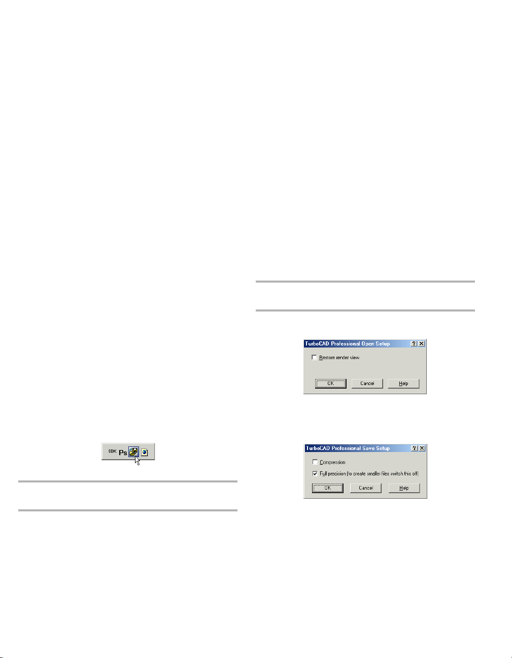
TurboCAD Reference Manual
Importing and Exporting Files
You can import and export data from other TurboCAD
formats, as well as formats of other CAD systems.
To import from another file type:
1. Select File / Open or Ctrl+O.
2. Under Files of type, select the format you want to
import.
3. If you want to specify conversion parameters, click
Setup.
4. Browse to the file, and double-click it or click Open.
To export to another file type:
1. Select File / Save As.
2. Under Save as type, select the format to which you
want to export.
3. If you want to specify conversion parameters, click
Setup.
4. Browse to the folder and assign a file name.
To import or export only certain components of a file, use
File / Extract From or Extract To. For example, you can
choose to import a drawing’s layers and blocks, or export
only print styles.
To insert the contents of another file as a block, create an
external reference (xref). See "External References" on page
266.
Batch Conversion
Available in TurboCAD Professional only
Menu: AddOns / SDK Samples / Tools / File Converter
conversion format. Click Run to convert all files in the
selected folder, and place the converted files in the target
folder.
TurboCAD Formats
There are three TurboCAD file formats, TCW, TCT, and
TCX, that you can use for saving vector graphics from within
TurboCAD.
TCW: (TurboCAD for Windows) - a file format for saving
vector graphics from within TurboCAD.
TCT: (TurboCAD Template) - a file format for saving
TurboCAD drawings as templates. TurboCAD uses a
template for starting a new drawing. You can save any
drawing as a template.
TCX: A file format for saving a TurboCAD drawing as an
ASCII file.
NOTE: If you need to save a drawing that is to be opened by
an earlier version of TurboCAD, you can save as Version 8.
TCW, TCT, TCX Import Setup
Restore render view: Opens the drawing in render mode.
The file must have been saved in render mode.
TCW, TCT, TCX Export Setup
NOTE: Display the SDK Samples toolbar by right-clicking in
any toolbar area and selecting SDK Samples.
Opens the TurboCAD File Convertor window, in which
you can select a source and destination folder for batch
conversion. Use the Files of type field to select the
2 For updates and additional information,
Compression: Saves the file in the TCT compressed format.
If the speed of operation is more important than the file size,
leave this option disabled.
Full Precision: TurboCAD stores your objects with the
maximum possible accuracy. Full Precision enables the
maximum depth of mathematical calculations performed to
Page 21

Chapter 1 Getting Started
generate and save entities. When disabled, entities will be
calculated and saved using only to four decimal points of
precision. This results in faster execution and smaller files,
but may compromise accuracy.
NOTE: Less than full accuracy can affect the ability of the
program to correctly display and edit objects at extremely
small scales. Unless you are using a slow machine, and know
you do not need extreme accuracy, you should leave Full
Precision on.
Other CAD Formats
The following formats can be read by TurboCAD, either for
import, export, or both. Some formats have a Setup in which
you can set certain parameters for conversion. If you do not
specify conversion parameters, the defaults will be used. (If
no Setup is indicated, the conversion requires no additional
input.)
NOTE: Some of these formats are available in TurboCAD
Professional only.
3DS: AutoDesk 3D Studio format. See "3DS File Import
Setup" on page 4 or "3DS File Export Setup" on page 4.
3DV: VRML Worlds (import only)
BMF: FloorPlan format (import only).
BMP: Bitmap format, TurboCAD for Windows (export
only). A bitmap is a representation of a graphic image
consisting of rows and columns of dots. See "BMP Export
Setup" on page 4.
CGM: Computer Graphics Metafile (import only)
DC, DCD: DesignCAD (import only)
DGN: Intergraph Standard file format. See "DGN Import
Setup" on page 5 or "DGN Export Setup" on page 5.
DWF: Drawing Web format. See "DWF Export Setup" on
page 5.
DWG: AutoCAD native format for vector graphics. See
"DXF (DWG) Import Setup" on page 6 or "DXF (DWG)
Export Setup" on page 6.
DXF: Drawing eXchange format, used by AutoCAD to
interact with other applications.
EPS: Encapsulated Post Script format. See "EPS Import
Setup" on page 6 or "EPS Export Setup" on page 7
FCD: FastCAD DOS format (import only)
FCW: FastCAD Windows format (import only). See "FCW
Import Setup" on page 7.
FP3: FloorPlan format (import only). See "FP3 Import
Setup" on page 7.
GEO: VRML Worlds (import only)
IGS: IGES format. See "IGS Import Setup" on page 7.
NOTE: IGS is a file format for a public domain called IGES
which is actually a neutral file format intended as an
international standard for the exchange of data between
different CAD/CAM systems. IGES is an ANSI standard
maintained by the IGES/PDES Organization (IPO), under the
direction of the National Institute of Standards and Technology
(NIST). The National Computer Graphics Association (NCGA)
acts as the administrator of the standard.
JPG: JPEG image compression standard, full 24-color.
TurboCAD for Windows (export only). See "JPG Export
Setup" on page 7.
JPG: JPEG format, SDK sample filter (export only)
MTX: MetaStream format. This format enables the creation,
delivery, and viewing of scalable 3D graphics. It enables you
to view images with Web browsers equipped with 3D plug-in
software, and to interact with 3D Web graphics in real time
by zooming, panning, or rotating objects within a Web
browser. It also scales objects in real time to match the
performance of your system. MetaStream compresses 3D
geometry and texture information, so that files can be
delivered quickly to your machine.
PLT: Hewlett-Packard Graphics Language. See "PLT Import
Setup" on page 8 or "PLT Export Setup" on page 8.
SAT: ACIS solid modeling file format for storing graphics
as ASCII (SAT - Save As Text) files. See "SAT Import
Setup" on page 8 or "SAT Export Setup" on page 8.
contact us at www.turbocad.com 3
Page 22
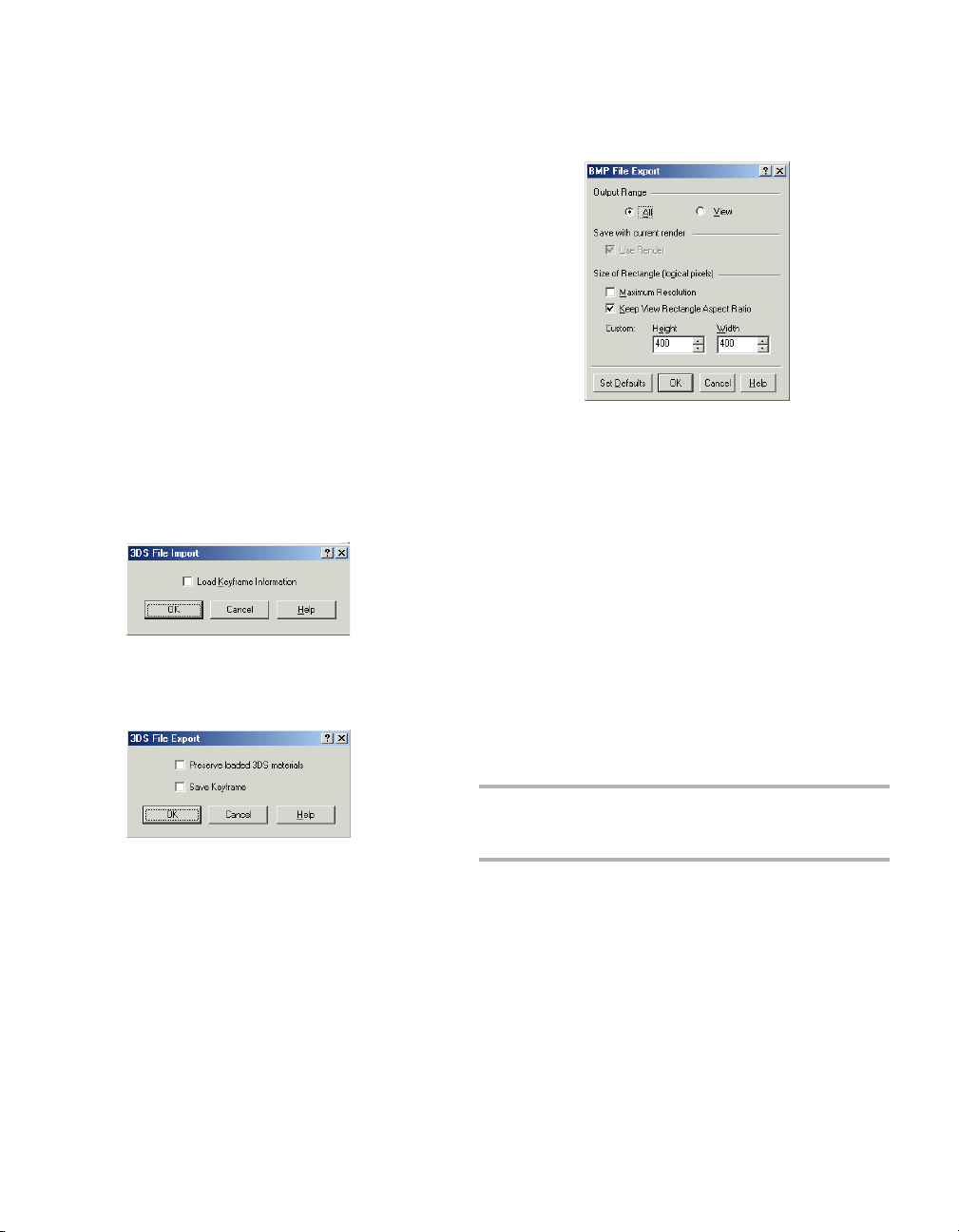
TurboCAD Reference Manual
SHX: Format that saves selected entities as a single shape,
that can be used in a line style (export only). This is not the
same as *.shx font format. See "SHX Export Setup" on page
9.
STL: Stereo Lithograpy format. See "STL File Export
Setup" on page 9.
STP: Step format.
WMF: Windows MetaFile format, saves graphics as a series
of records that correspond to graphics function calls, such as
drawing straight lines, curves, filled areas, and text. "WMF
Import Setup" on page 9 or "WMF Export Setup" on page 10
WRL: Format for saving graphics as a Virtual Reality Model
Language (VRML) description. See "WRL Export Setup" on
page 10.
WRZ: VRML Worlds
3DS File Import Setup
Load Keyframe Information: Accepts or ignores the
keyframe 3DS file data.
3DS File Export Setup
BMP Export Setup
Output Range: Creates an export file either out of the entire
drawing (All) or only the part that is currently in view
(View).
Use Render: Available only when Render or Hidden Line
mode is active. If checked, the exported image will show the
render displayed on the screen.
Size of Rectangle: Sets up the resolution for the exported
graphics. By default, these values are 400 x 400 but you can
customize the height and width
• Maximum resolution: The drawing will be defined
by a rectangular matrix of 2000 x 2000 logical pixels.
If there is at least one image object, this is set to 1000
x 1000.
• Keep View Rectangle Aspect Ratio: Keeps the same
ratio of length to width.
NOTE: You can determine an object’s type by using the
Selection Info Palette. See "Selection Info Palette" on page
Preserve loaded 3DS materials: Saves unique materials
162.
from a 3DS file. If not checked, saves TurboCAD materials.
Save Keyframe: Saves the hierarchical structure of entities
in a file. Do not check this option for 3DS files that you want
to use as 3DS symbols in FloorPlan.
4 For updates and additional information,
Page 23

Chapter 1 Getting Started
DGN Import Setup
View Number: By default, the view number is 1.
Line Widths: You customize a set of drawing line widths
identified by the indexes (0, 1, 2, etc.). To do this, use the
two-column Line Width control ,where the Index column
provides a reference to a particular line width, and the Width
column is a data entry field. You can scale the line width
values, using the Width Scale data entry field.
Fonts: As with the drawing line widths, the import file's
fonts are indexed. For every index in the Index column, you
can select a font from the corresponding drop-down list in
the Font column. In addition to the options of the Fonts
control, there is the Default Font entry field whose
drop-down list lets you select a common font for the ones
you haven't changed.
Set Defaults: Instead of customizing the imported file
options, you can apply the default settings for the DGN file
import. To do this, click Set Defaults.
Default font index to export: The DGN format requires the
export file's fonts to be indexed. For every listed font, you
can select an index. In addition to the options of the Fonts
control, there is the Default Index entry field whose
drop-down list lets you select a common index for the fonts
you have not changed.
DWF Export Setup
Output Format: If Readable is selected, you can later open
the exported file to view and/or edit via a text editor.
Skip Invisible Layers: Invisible layers will not be included
in the export file. See "Setting Up Layers" on page 99.
Precision: Sets the export precision between 16 and 32 bits.
For simple drawings there is little visual difference. More
complex drawings and fine details require higher precision,
but increasing the precision increases the file size.
DGN Export Setup
Ve rs io n : Choose between Versions 7 and 8.
contact us at www.turbocad.com 5
Page 24
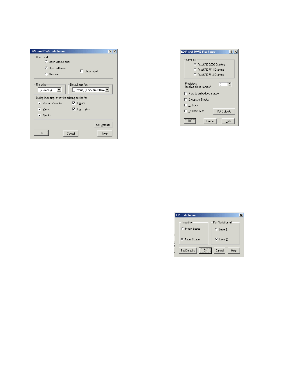
TurboCAD Reference Manual
DXF (DWG) Import Setup
Open mode:
• Open without audit: Opens the file without checking
it. If the file has errors, it will not be opened.
• Open with audit: Opens the file and corrects errors
when possible. The report is displayed only if errors
are found. The file is checked is after it is loaded into
memory, though if the file is very corrupt it may not be
able to be loaded into memory.
• Recover: Opens the file and corrects errors. The report
is automatically displayed, regardless of errors. The
file is checked before loading it into memory.
File Units: Replaces the units of an imported file with the
selected units.
Default text font: Sets a default import font.
Overwrite existing entries for: AutoCAD stores the
settings (or values) for its operating environment and some
of its commands in system variables. Checking this box
overwrites these settings. In TurboCAD, these settings
include World units, the numerical display format, the
angular system, etc.
You can overwrite system variables for objects under the
following conditions: the DXF/DWG drawing is inserted
into an open file, and both files (the imported file and the
receiving file), have system variables (views, blocks, layers
and/or line styles) of the same names.
DXF (DWG) Export Setup
Save As: Select the AutoCAD version.
Precision: The number of decimal places for numerical
values of the exported file.
Rewrite embedded images: Relevant for files that contain
image objects. Choose whether to replace images.
Groups as Blocks: Displays objects included in groups as
blocks when imported into AutoCAD.
Unblock: Explodes blocks into its constituent objects.
Explode Text: Explodes any text into its constituent parts.
EPS Import Setup
Import to: Choose whether the imported file will open in
Model Space or Paper Space.
PostScript Level: Level 2 is a more sophisticated version of
PostScript. It provides color extensions, support for fonts
with many characters, filters (for compression, etc.) and
improved image handling (inclusion of JPEG files, etc).
6 For updates and additional information,
Page 25
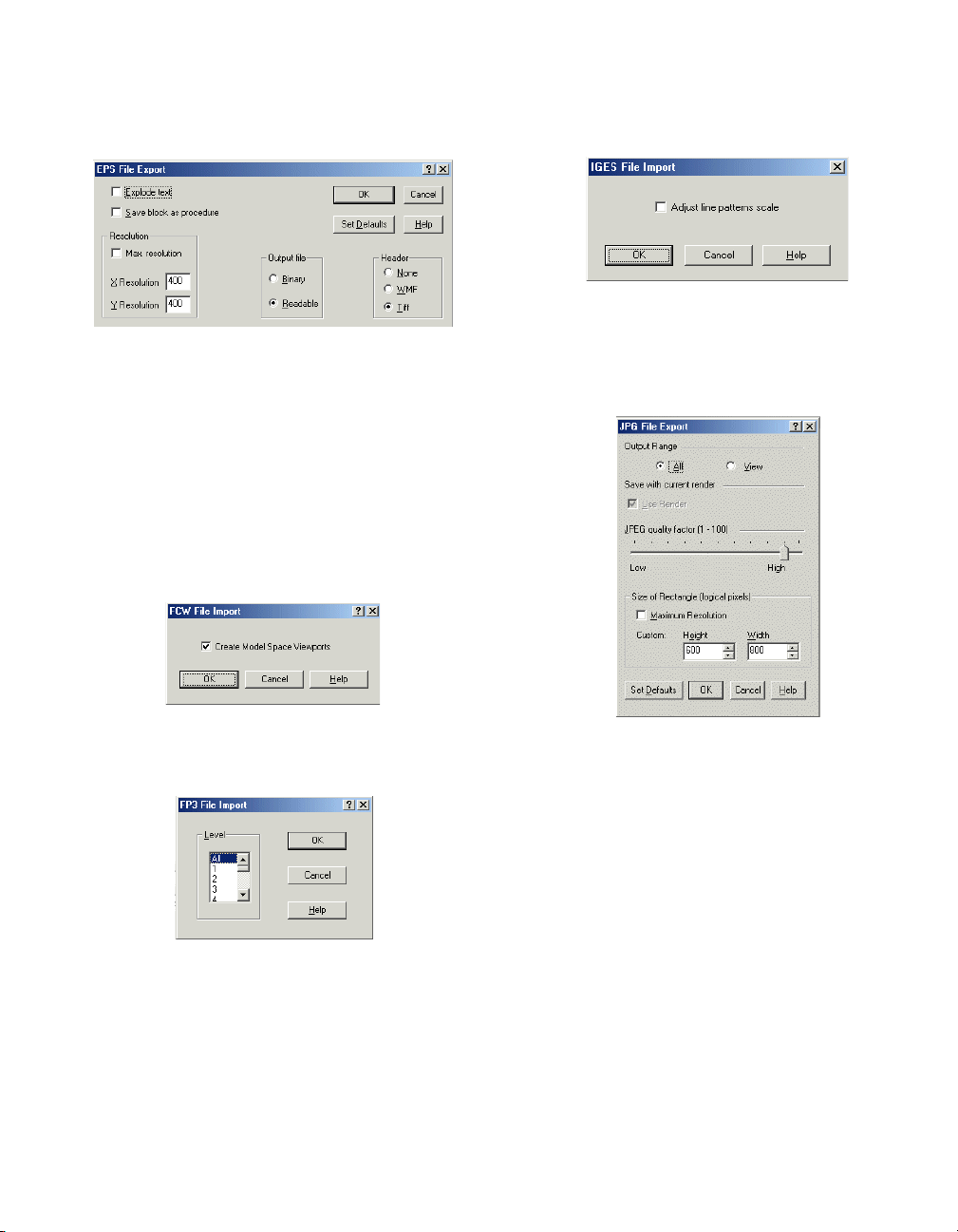
Chapter 1 Getting Started
EPS Export Setup
Explode Text: Explodes any text into its constituent parts.
Save block as procedure: Saves the drawing's blocks as
procedures in the PostScript language.
Resolution: Sets the horizontal and vertical resolutions for
the two-dimensional presentation of your drawing. Check
Max Resolution to set the maximum 1600x1600 resolution.
Output file: Exports to a binary or readable format.
Header: Specify whether to include a preview image, and in
what format.
FCW Import Setup
IGS Import Setup
Adjust line pattern scale: Line style for improving line
display. Because IGS files can be created in a variety of
ways, either option (on or off) may work to improve
precision during import.
JPG Export Setup
Create Model Space Viewports: Specify whether to create
viewports for the Model Space presentation of your drawing.
FP3 Import Setup
Level: Choose to import all levels of the floor plan, or to
import only a selected level.
In FloorPlan, each story is a level. Within each level,
drawing objects are automatically organized into layers.
TurboCAD supports the FP3 layer structure.
contact us at www.turbocad.com 7
Output Range: Creates an export file either out of the entire
drawing (All) or only the part that is currently in view
(View).
Use Render: Available only when Render or Hidden Line
mode is active. If checked, the exported image will show the
render displayed on the screen.
JPEG quality factor: Your goal is generally to pick the
lowest quality setting, or smallest file size, that
decompresses into an image indistinguishable from the
original. This setting can vary, but here are some rules of
thumb. For good-quality, full-color source images, the
default quality setting (Q 75) is very often the best choice.
This setting is about the lowest you can go without expecting
to see defects in a typical image. Try Q 75 first; if you see
defects, then increase. If the image was less than perfect
Page 26
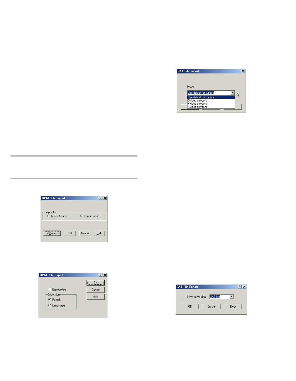
TurboCAD Reference Manual
quality to begin with, you might be able to drop down to Q
50 without objectionable degradation. On the other hand,
you might need a higher quality setting to avoid further loss.
This is often necessary if the image contains dithering or
moire patterns. Except for experimental purposes, avoid
values above Q 95; Q 100 will produce a file two or three
times as large as Q 95, but with negligible quality
improvement.
Size of Rectangle: Sets the resolution for the exported
graphics. By default, these values are 600 x 800 but you can
customize the height and width
• Maximum resolution: The drawing will be defined
by a rectangular matrix of 2000 x 2000 logical pixels.
If there is at least one image object, this is set to 1000
x 1000.
NOTE: You can determine an object’s type by using the
Selection Info Palette. See "Selection Info Palette" on page
162.
PLT Import Setup
Import to: Choose whether to open the imported file in
Model or Paper Space.
PLT Export Setup
Orientation: Sets the paper orientation to Portrait (vertical)
or Landscape (horizontal).
SAT Import Setup
Mode: Choose one of the modes for representing SAT
objects.
Default: The choice of the polygon type is determined by the
surface type in the solid object model (planar, cylindrical,
spherical, toroidal, etc.)
3, 4, n-sided polygons: The number of sides of polygons
used for object representation.
If you wish to check what type of polygon is used for the
object presentation in an imported SAT file, do the
following.
1. Once the SAT file has been imported, select an object
in the drawing, make a block of it, and bring this block
onto the paper of the TurboCAD desktop.
2. Open the Properties window for this block, open the
Block Insertion page, and assign non-zero values to
the rotation coordinates.
3. When a 3D view of your object is displayed, select the
object and explode it.
4. After this you can display individual elements
(polygons) of the object by selecting the different parts
of objects.
SAT Export Setup
Explode text: Explodes any text into its constituent parts.
8 For updates and additional information,
Select the SAT version for export.
Page 27
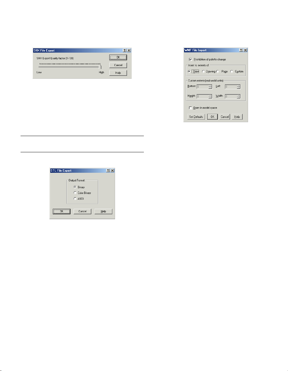
Chapter 1 Getting Started
SHX Export Setup
SHX Export Quality Factor: A high value creates shapes
that more accurately represent the selected geometry.
However, large values tend to create shapes that contain
more coordinate data and can be a processing burden during
regeneration. Low values create less accurate shapes that are
more quickly processed. You may need to experiment with
different values.
NOTE: SHX export does not create an *shx font file. Once
created, the results cannot be edited.
STL File Export Setup
Binary: Saves to a binary file.
Color Binary: Saves to a color binary file.
ASCII: Saves to an ASCII text file.
WMF Import Setup
Prohibition of palette change: Prevents TurboCAD from
changing the color palette.
Insert to extents of: Sets the size of the imported drawing.
• View: The size is based on the current view.
• Drawing: The size is based on the entire drawing.
• Page: The size is based on the paper sheet.
• Custom: Define your own size.
Custom extents: Enter coordinates and dimensions of the
rectangle that encloses the drawing.
Open in Model Space: Opens the imported drawing in
Model Space. The drawing is placed on the default By
World workplane.
contact us at www.turbocad.com 9
Page 28
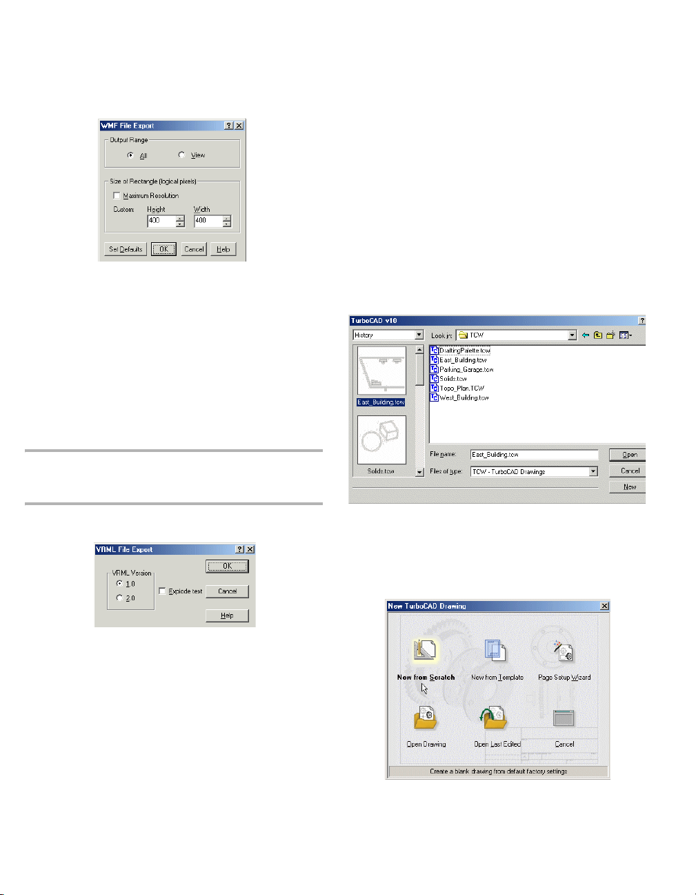
TurboCAD Reference Manual
WMF Export Setup
Output Range: Creates an export file either out of the entire
drawing (All) or only the part that is currently in view
(View).
Size of Rectangle: Sets the resolution for the exported
graphics. By default, these values are 400 x 400 but you can
customize the height and width
• Maximum resolution: The drawing will be defined
by a rectangular matrix of 8000 x 8000 logical pixels.
If there is at least one image object, this is set to 1000
x 1000.
NOTE: You can determine an object’s type by using the
Selection Info Palette. See "Selection Info Palette" on page
162.
Starting TurboCAD
If you accepted the default installation settings, TurboCAD
can be accessed via the Windows Start / Programs menu.
1. Click the Start button on the Windows taskbar.
2. Select Programs / IMSI, and select the version you
have installed.
You can also start TurboCAD by double-clicking the desktop
icon.
In the opening screen, you can view a History of drawings
previously opened, browse to folders containing drawings
you want to open, or open a Template. You can also use this
window to import files of other types.
WRL Export Setup
Select a version of VRML file to save. You can also explode
the drawing text while creating the file for export.
10 For updates and additional information,
If you want to create a new drawing, click New.
You can also close this window by clicking Cancel. You can
then select File / New within TurboCAD to create a new
drawing. The New TurboCAD Drawing window appears,
in which you specify what type of file you want to open.
Page 29
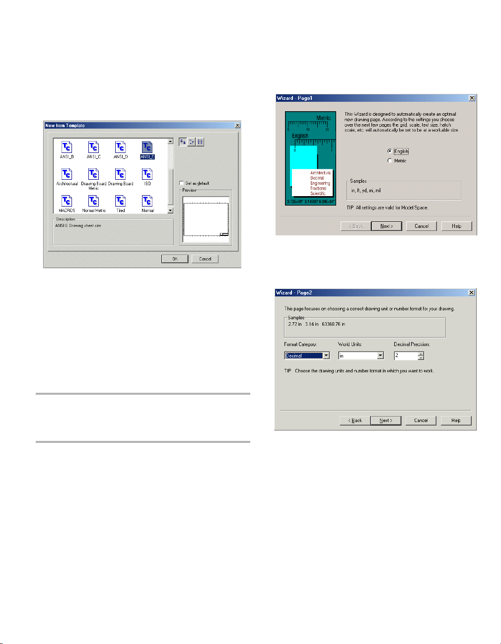
Chapter 1 Getting Started
New from Scratch: Creates a new blank drawing with the
default settings.
New from Template: Enables you to select a predefined
template, which has size, units, and layout defined.
Page Setup Wizard: Opens the step-by-step guide for
setting page size and scale.
Open Drawing: Opens an existing drawing. Browse to the
desired folder to locate the file. For acceptable file types, see
"Importing and Exporting Files" on page 2.
Open Last Edited: Opens the last file you worked on.
In the first page you can choose between English and Metric
units.
On the second page you can set the type of unit you want to
use - architectural (1’-3”), decimal (3.75 ft.), scientific, etc.
You can also specify the main unit (inches, feet, yards) and
the precision of the units.
Page Setup Wizard
A step-by-step guide to setting page size and drawing scale.
NOTE: This is not exactly the same as the Page Setup used
for printing, but any relevant parameters you set in this wizard
will appear in the Page Setup. See "Page Setup" on page
451.
If you selected Page Setup Wizard in the New TurboCAD
Drawing window, the wizard opens automatically. You can
also access it via File / Page Setup Wizard.
contact us at www.turbocad.com 11
Page 30
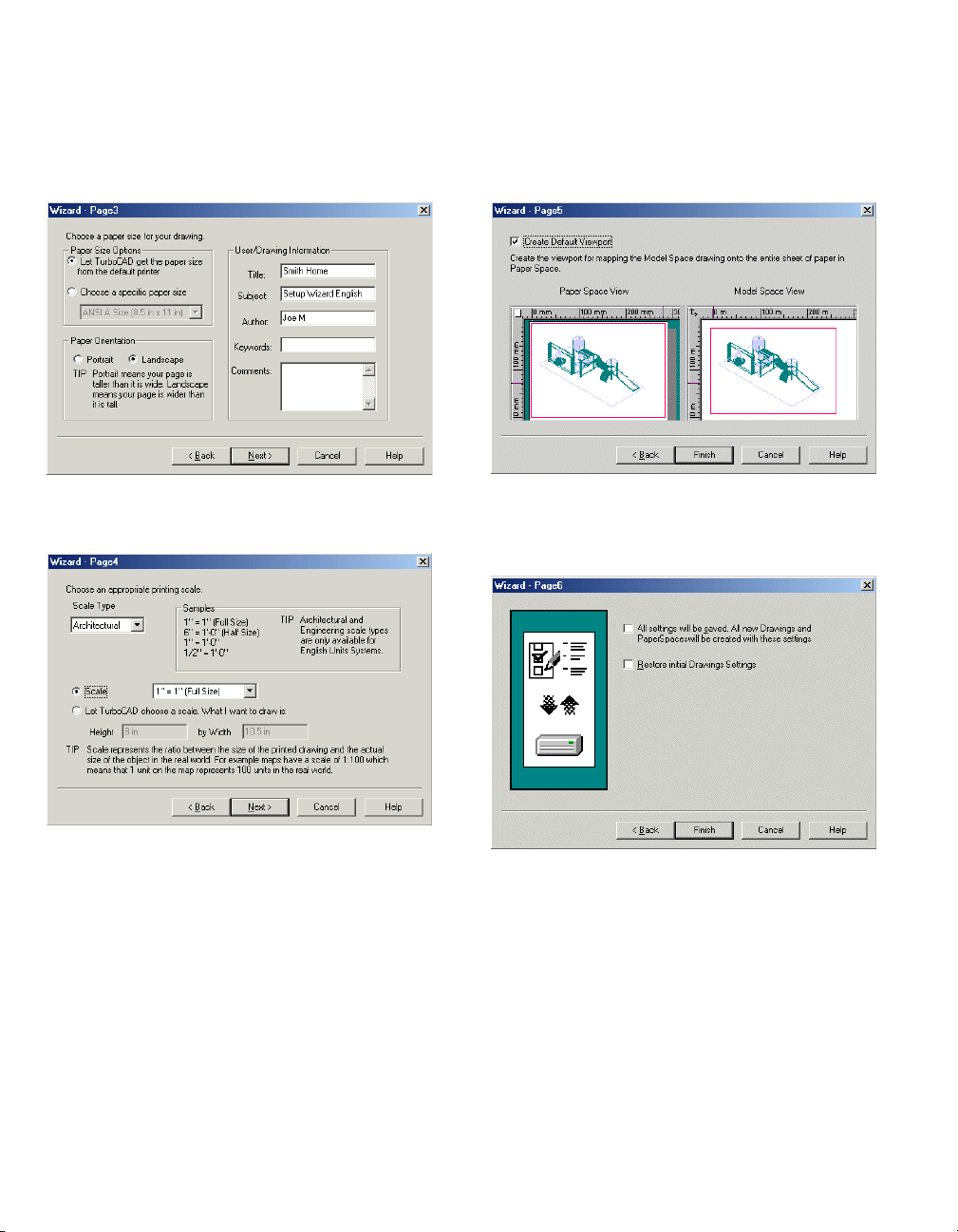
TurboCAD Reference Manual
The third page contains options for paper size and orientation
- these are used when printing. You can also enter drawing
information such as title, author, and comments.
The fourth page enables you to set the printing scale. This is
the size of the objects when printed, relative to their actual
size specified in the drawing.
from Paper Space, you get a hard copy of the Plan view of
the current drawing because the Plan view is the default view
for Model Space.
The sixth and final page enables you to save the settings for
future drawing or to restore the initial settings. Settings can
be edited in the the TC Explorer Palette (see "TC Explorer
Palette" on page 74.).
The fifth page enables you to create a default viewport for
mapping the Model Space drawings onto the paper sheet as
defined in Paper Space. When printing the default viewport
12 For updates and additional information,
Page 31

Chapter 1 Getting Started
Opening and Saving Files
Within TurboCAD you can choose to open a saved file or
start a new file. You can also open new and saved files from
within TurboCAD, and there are several options for saving
files.
NOTE: The General page of the Program Setup contains
several settings for opening and saving files. See "General
Setup" on page 39.
Opening Files
Menu: File / Open
Hotkey: Ctrl+O
Files of type: By default, you will open a *.tcw file. Use this
list if you want to open a file of a different format. See "Other
CAD Formats" on page 3.
Open as read-only: A read-only file can be viewed only; it
cannot be edited.
Description: Displays text entered in the Subject field of the
Summary Info window. See "Summary Info" on page 14.
Show Preview: Displays a thumbnail of the drawing. Only
TurboCAD files (*.tcw and *.tct) can display previews.
Setup: When importing files of other formats, provides
access to conversion options.
Saving Files
Menu: File / Save, Save As
Hotkey: Ctrl+S
Saves the current drawing to disk. If the file was not
previously saved, the Save As window will appear.
Save as type: By default, you will save the file as a *.tcw
file. Use this list if you want to save (export) the file to a
different format. See "Other CAD Formats" on page 3.
Setup: Enables you to set parameters for the saved *.tcs file
(see "TCW, TCT, TCX Export Setup" on page 2). When
exporting to another file format, provides access to
conversion options.
Save:
• Drawing: Saves the entire drawing.
• Selection: Saves the selected objects only.
If Prompt for Summary Info is checked in the General
page of the Program Setup (Options / General), the
Summary Info window will appear before saving.
contact us at www.turbocad.com 13
Page 32

TurboCAD Reference Manual
Summary Info
Menu: File / Summary Info
Records general information to be saved with the drawing.
If Prompt for Summary Info is checked in the General
page of the Program Setup (Options / General), the
Summary Info window will appear when you save the
drawing.
File Name and Directory: Information for files that have
already been saved.
Keywords: Text used when searching for this file.
Subject: Descriptive text that appears in the Open and Save
windows. This text can also potentially be used by Windows
file search utilities.
• Metafile: Suitable for small files because it displays
more detail. Symbol previews are generally stored
using this option.
Create Preview by: Saves the preview as the plan view or
by the current view and render mode.
Getting Help
There are several ways to get help on any TurboCAD topic.
Online Help
The Help menu provides access to the online help, which
basically contains the same content as this book.
The help is also context-sensitive, which can be accessed in
several ways:
• Click the Help button (question mark icon), then click
on the tool button, menu item, tab, or palette in
question.
• Place the cursor over a button, menu item, or palette, or
highlight a menu item, and press F1.
• Press F1 while using a tool or window.
• Press the Help button on a window.
To see a tool tip for an icon, hold the cursor over the button
for a second or two. The tool tip will appear, showing the
name of the tool.
TIP: Select Help / Keyboard to see a list of keyboard
shortcuts.
TIP: If a drawing is being saved as a symbol, the Title should
be a short description of the symbol, and Subject contain a
more detailed description. See "Symbols" on page 266.
Save Preview Graphics with Drawing: Sets the type of
graphic image that will be stored with the drawing, so that it
can be previewed in TurboCAD and in other Windows
programs.
• None: No preview graphics will be saved.
• Bitmap: Suitable for large files because the bitmap
will use the same amount of space no matter how
complex the drawing is.
14 For updates and additional information,
Select Help / Tip of the Day for helpful hints.
Web Tutorials
There are several online demo tutorials that can be accessed
from the page that appears in the Internet Palette (View /
Internet Palette). You need the Macromedia Flash plug-in
to view these tutorials.
These short, animated demos demonstrate some basic
concepts about the user interface, and show you how to use
some of the TurboCAD tools.
Page 33

Chapter 1 Getting Started
Help on the Internet
Select Help / TurboCAD on the Web. Each item in the
submenu opens the Internet Palette to the selected web site.
Forums
Go to www.turbocad.com and click User Forums. Choose
the forum for the version of TurboCAD you have.
The first time you enter the forums, you will be asked to
register. Registration helps maintain your preference
settings, and your real name and email address help us all
interact with you better.
The TurboCAD Forums are the place to get the absolute best
technical support. All the support comes from other users,
including professional experts (architects, engineers, and
drafters) from all over the world, some using TurboCAD
full-time. There are also a few IMSI employees and
programmers participating. Ours are perhaps the most active
forums in the CAD industry. It's free, and everyone is quite
eager to help. In fact, forum users help IMSI develop and
improve the software!
Feel free to reply to a message, post a new message, or create
your own new thread. Introduce yourself. Formalities are
waived, and you are welcome regardless of skill level. This
is where we get our questions answered and our struggles
resolved on a regular basis.
Technical Support
Go to the support section of http://www.turbocad.com for
detailed support options.
Paid technical support is available by calling 877-827-8776.
Technical Support will work closely with you to solve any
problems related to our software. Please give our support
technicians as much information as possible. Remember that
they are not in front of your computer and that they need your
help to diagnose the problem.
On occasion, a problem can be traced to hardware, or to
another software application. Our technician will supply as
much support as possible in these cases, but they are not
authorized to support products manufactured or published by
another company.
You might find that e-mail is a more convenient way to get
technical support. If you do send e-mail, provide as much
information as you can about your system and about the
problem.
Technical Support CheckList
You may already have the information you are looking for.
Before calling, check this manual thoroughly. To receive the
fastest response to your technical questions, please be in
front of your computer with TurboCAD running, and be
prepared to provide the following information before you
call or send e-mail:
• The type of computer and Windows version you are
using.
• The name, version number, and other information
about your specific version of the product. (To find this
information, select Help / About TurboCAD from the
TurboCAD menu.)
• The exact sequence of events that created the problem.
Verify that you can reproduce the problem by
following the same series of steps.
• The exact wording of any error messages.
• Steps you've taken to find the answer to your question,
including resources used.
• The results of any steps you have undertaken to resolve
the problem.
contact us at www.turbocad.com 15
Page 34

TurboCAD Reference Manual
16 For updates and additional information,
Page 35

2 User Interface
This section provides information on your working
environment in TurboCAD. In addition to descriptions of the
UI and its components, information is provided about
program and drawing setup, customization, and windows.
Object properties, and the various means of setting and
changing properties, are also covered.
Components of the UI
The main area of the TurboCAD screen is the drawing area.
When creating and inserting 2D and 3D objects, you
typically work in Model Space, and when putting your
model on paper, Paper Space is used.
By default, the background color is white, but you can
change that by selecting Options / Background Color and
choosing another color.
Nearly all components of the screen can be customized. See
"Customizing the UI" on page 33.
Drawing Area: Model Space and Paper
Space
Menu: Workspace / Model Space, Paper Space
For creating and laying out your drawing, TurboCAD
provides you with two drawing environments: Model Space
and Paper Space.
• Model Space is the environment in which you create
your drawing, usually called a model. In this area you
do drafting and design work, creating two-dimensional
drawings or three-dimensional models.
• Paper Space is the environment in which you create the
final layout of your drawing for printing or plotting it
on paper. In Paper Space you usually arrange the
drawing's elements on a sheet of paper.
You can use the small button at the top left corner, at the
intersection of the rulers, to toggle between Model and Paper
Spaces.
NOTE: If the rulers are turned off, this button will not appear.
Use Workspace / Rulers to toggle the ruler display.
You can also use the icons on the Standard toolbar to switch
between spaces.
There are also workspace tabs at the lower left corner of the
screen. By default, each file starts with one tab for Paper
Space. Click the tabs to switch spaces.
NOTE: If scroll bars are turned off, these tabs will not appear.
Use Workspace / Scroll Bars to toggle the scroll bar display.
NOTE: Floating Model Space enables you to use Model Space
tools within a viewport in Paper Space. See "Floating Model
Space" on page 449.
contact us at www.turbocad.com 17
Page 36

TurboCAD Reference Manual
Menu Bar
All tools and options are available by selecting them from
the menus at the top of the screen - File, Edit, View, etc.
(Most tools are available in toolbar icons as well).
For details on all menu options, see "Menus" on page 22.
Toolbars
Menu: Vie w / Tool bars
Toolbars are groups of related icons. They can be located on
top and below the screen, and to either side of the screen.
You can also create tabbed toolbars and popup toolbars that
appear when you open the local menu. You can modify a
toolbar’s icons and create your own toolbars. See
"Customize Toolbars" on page 34.
In addition to the default toolbars you see when you first start
TurboCAD, there are numerous other toolbars you can
display. There are two ways to access additional toolbars:
• Open the Toolbars and Menus page of the Program
Setup (Options / Toolbars and Menus). This
window contains a list of all available toolbars; check
the ones you want to see.
• Right-click in any toolbar area. The local menu that
appears contains the list of all available toolbars; select
a toolbar to add or remove from the screen.
NOTE: If you want to use preset toolbar configurations for 2D
and 3D work, you can click Show Configuration Button in
the Toolbars and Menu window (View / Toolbars). Full
removes the toolbar, and 2D and 3D are optimized for work in
the two modes.
By default, the Stand ard toolbar appears at the top of the
screen, and the Property toolbar (see "Property Toolbar" on
page 59) appears just below it. Drawing tools appear along
the left side.
Icons that have a small yellow triangle in the corner are
fly-outs; if you click one and hold the mouse button, the
entire toolbar will “fly out,” and you can select the desired
icon.
18 For updates and additional information,
Page 37

Chapter 2 User Interface
Docking Toolbars
By default, some toolbars are docked along the sides of the
screen, and when you display another toolbar it appears
“floating” on the screen. You can dock and undock all
toolbars, and the same applies for palettes as well.
You can drag a toolbar by picking it on its top or bottom edge
(for vertical toolbars) or either side edge (for horizontal
toolbars).
For palettes, pick the horizontal edge near the top.
Moving a toolbar to any edge of the screen will dock it to that
edge. Docking to either side creates a vertical toolbar,
docking to the top or bottom of the screen creates a
horizontal toolbar. You can also move a toolbar onto the
drawing area, where it will “float” on the screen.
Status Bar
Menu: Workspace / Status Bar
Located at the lower left corner of the screen, the Status Bar
lets you know the current status of the model.
For example, if you have just activated the Line tool, the
Status Bar will contain the prompt “Define the start point of
the line.”
Inspector Bar
Menu: Workspace / Inspector Bar
Enables you to create objects by defining some or all of its
numerical parameters.
By default, the Inspector Bar is located immediately below
the drawing window.
NOTE: You can customize the Inspector Bar appearance, by
choosing Classic or Custom in the Desktop page of the
Program Setup (Options / Desktop). You can also display or
hide the Inspector Bar on this page.
If you want to prevent a toolbar or palette from being
dockable, click its magnet symbol on its top right corner.
When the magnet is deactivated (grayed out), the toolbar or
palette can only float and will not dock to any sides.
Click the “X” symbol to close the toolbar.
contact us at www.turbocad.com 19
For most tools, the Inspector Bar is divided into three parts.
On the left side are two icons, Cancel and Properties.
• Cancel: Ends an operation without completing it. For
some tools, once the operation is complete the tool
remains active. You must click Cancel, or activate
another tools, to exit the tool. The hotkey for Cancel is
the Esc key.
Page 38

TurboCAD Reference Manual
• Properties: Opens the Properties window for the
object you are creating. See "Object Properties" on
page 59.
The middle section of the Inspector Bar contains the numeric
fields. For example, when creating a line segment in the
Polyline tool, you can set the Length, Angle, and Start and
End Widths. For a circle, the fields would be Radius,
Diameter and Circumference. When moving the cursor to
position or size an object, the values in the fields update
dynamically.
You can access the numeric fields via the cursor, or by
pressing Tab or Ctrl+E. You can also press Tab to scroll
forward to the next field. Return to the drawing by pressing
Esc or clicking in the drawing.
TIP: If you want to jump from the Coordinate Fields to the
Inspector Bar, first press Esc, then Ctrl+E.
If you enter a value and press Enter, Any Ortho or snap
modes are ignored. You can also enter the results of
mathematic expressions from the Calculator. See
"Calculator Palette" on page 30 and "Using Expressions in
Data Fields" on page 31.
Locking: For some fields you can lock their values by
clicking the lock symbol. This means that no matter where
you place the cursor, the value will remain fixed.
There are two common local menu options that appear for
many functions: Finish and One Step Back.
• Finish: Completes the operation and exits the tool. For
instance, when creating a polyline, you can click
Finish after creating the last segment. The hotkey for
Finish is Alt+F.
NOTE: For many tools, double-clicking when creating the last
component of an object is equivalent to clicking Finish.
• One Step Back: For tools that require multiple steps,
this enables you to scroll backward through the steps
already completed until you reach the desired start
point, then continue working.
When in Select Edit mode, the Inspector Bar has a different
appearance. The numeric fields enable you to change the
size, scale, and rotation of the selected objects, while the
local menu options include Make Copy, Selector properties,
etc. Size and Position fields for 3D objects are turned off by
default. See "Select Edit" on page 166.
NOTE: The options that appear on the Inspector Bar in Select
Edit mode depend on whether you are in 2D or 3D Selector
mode, and can be changed. See "2D / 3D Selector" on page
155.
Customizing the Inspector Bar
The right side of the Inspector Bar contains options relevant
for the tool or mode.
NOTE: All options on this section of the Inspector Bar can also
be accessed from the local menu, opened by right-clicking.
20 For updates and additional information,
You can remove any of the fields or local menu option icons
by right-clicking anywhere on the Inspector Bar (except the
numeric fields). This opens a local menu in which you can
deselect any of the controls.
You can also change the width of any of the numeric fields
by dragging either side with the mouse.
Page 39

Chapter 2 User Interface
Coordinate Fields
When creating or sizing objects, you can define points by
entering them directly into the Coordinate Fields. By default,
this toolbar is located at the lower right corner of the screen.
When moving the cursor, the values in the fields update
dynamically.
The type of coordinates depends on the coordinate system
you are using. In the absolute and relative coordinate
systems you use X, Y coordinates. In the polar coordinate
system you enter an angle and distance. See "Coordinate
Systems" on page 87.
You can access the numeric fields via the cursor, or by
pressing Shift+Tab or Ctrl+R. You can also press Tab to
scroll between Coordinate fields.
TIP: If you want to jump from the Inspector Bar to the
Coordinate Fields, first press Esc, then Ctrl+R.
If you enter a value and press Enter, Any Ortho or snap
modes are ignored. You can also enter the results of
mathematic expressions from the Calculator. See
"Calculator Palette" on page 30 and "Using Expressions in
Data Fields" on page 31.
Locking: You can lock a coordinate by clicking the lock
box. This means that no matter where you place the cursor,
the value will remain fixed.
The Coordinate Field also provides access to snap modes.
Disable the SNAP button to temporarily turn off any running
snaps, and disable the GEO button to temporarily turn off
any running geometric aids Right-clicking on either the
SNAP or GEO fields opens the Drawing Aids window. See
"Snaps" on page 91.
Palette Area
Menu: View
Located by default on the right side of the screen, the tabbed
palettes provide convenient access to many features, such as
Blocks, the Internet, Properties, etc.
For details on each palette, see "Palettes" on page 28.
You can also lock coordinates by using the Lock options in
the Modes menu.
TIP: The Coordinate Field locks are particularly useful when
you lock just one field. If you use a locked value in one field,
you can then set the second coordinate using the mouse. This
makes it easy to define a series of points along a specific
horizontal or vertical line.
contact us at www.turbocad.com 21
Page 40

TurboCAD Reference Manual
Rulers
Menu: Workspace / Rulers
You can work with rulers to have a visual representation of
the current dimensions.
Rulers are only displayed for orthographic views (top, left,
right, etc.) and display the current Model Space or Paper
Space units (see "Space Units" on page 49).
TIP: Another handy visual aid, which can be used in tandem
with rulers, is the grid. See "Grid" on page 89.
Scroll Bars
Menu: Workspace / Scroll Bars
Menus
The menu bar, located at the top of the screen, provides
access to all commands, tools, and functions.
NOTE: You can customize the contents of the all menus, and
add new menus via Tools / Customize. See "Customize
Menus" on page 37.
This section lists the contents of each main menu, and refers
you to the information on each menu item.
File Menu
New: Starts a new TurboCAD drawing.
Open: Opens a drawing or converts from another format.
See "Opening and Saving Files" on page 13.
Extract From: Extracts selected components (layers, UCS,
blocks, etc.) from another drawing into the current drawing.
Close: Closes the current drawing.
Save: Saves the current drawing to disk.
Save As: Saves the current drawing under a new name, or
exports to another format. See "Opening and Saving Files"
on page 13.
Save All: Saves all open drawings.
Extract To: Extracts selected components (layers, UCS,
blocks, etc.) from the current drawing to other drawings.
Publish to HTML: Exports the current drawing to an
HTML file. See "Publish as HTML" on page 455.
Store Thumbnail: A thumbnail of the file will be created,
which can be seen in the Open and Save windows.
Your drawing can be larger (much larger!) than what you see
on the screen. The scroll bars can be used to pan to a different
area of your drawing. Click on the arrows at the ends of the
scroll bars to move a small amount. Drag the scroll box itself
to move faster.
22 For updates and additional information,
TIP: Another way to create thumbnails is to go to Windows
Start menu / All Programs / TurboCAD / Thumbnails
Setup. Check the file types for which you want to generate
thumbnails.
Page Setup Wizard: Step-by-step guide to setting up the
page size and drawing scale. See "Page Setup Wizard" on
page 11.
Page 41

Chapter 2 User Interface
Summary Info: View or edit document information about
the current drawing. See "Summary Info" on page 14.
Print Preview: Displays a preview before printing.
Page Setup: Options for printing your drawing. See "Page
Setup" on page 451.
Print: Prints the current drawing. See "Printing" on page
449.
Send: Sends the current drawing as an email attachment,
using Microsoft Mail or Outlook.
Recent File: Reopens one of the most recently used files.
Exit: Exits TurboCAD.
Edit Menu
Undo: Reverses the previous action (Ctrl+Z). You can set
undo options in Options / Preference (see "Preference" on
page 41).
Redo: Reverses the effect of the previous Undo command.
Cut: Removes selected objects and places them on the
Windows clipboard (Ctrl+C).
Copy: Copies selected objects to the Windows clipboard.
Paste: Pastes objects into the drawing from the Windows
clipboard. You can paste drawing objects, text, images, or
Windows metafile data (Ctrl+V).
Paste Special: Pastes objects from the clipboard as data or
as OLE objects. See "Paste Special" on page 150.
NOTE: When using Paste and Paste Special when Script
Blocking in Norton AntiVirus is enabled, you may have
problems with pasted objects. For example, *.doc files can
become uneditable pictures.
Clear: Removes the selection, all objects, a single
construction, or all constructions from the drawing.
Relocate Block Reference Point: See "Relocating a Block
Reference Point" on page 261.
Finish to Edit Block: Ends the editing of a block. See
"Editing a Block" on page 261.
Edit Group Content: Edit the content of the selected group.
See "Editing a Group" on page 256.
Finish to Edit Group: Ends the editing of a group. See
"Editing a Group" on page 256.
Select: Activates the Select tool. See "Selecting Objects" on
page 155.
Edit Tool: Activates node editing. See "Edit Tool" on page
193.
Select All: Selects all objects in the active drawing (Ctrl+A).
Select By: Selects objects that meet specified criteria See
"Selecting Objects" on page 155.
Copy Entities: Create single or multiple copies of objects.
See "Copying Objects" on page 174.
Transform: Quickly move, rotate, or scale objects. See
"Transforming" on page 185.
Transform Recorder: Record transformations to apply to
other objects. See "Transform Recorder" on page 190.
Links: Changes OLE object links. See "Editing Links to
OLE Objects" on page 151.
Object: Edits OLE objects in its source application. See
"Editing Inserted OLE Objects" on page 151.
Hyperlink: Jumps to a specified file or URL. See
"Hyperlinks" on page 151.
Facet Edit: Moves or rotates individual facets of a solid
object. See "Facet Edit" on page 371.
Imprint: Modifies a facet of a solid by imprinting a closed
2D profile object. See "Imprint" on page 384.
Update Compound Profile: Enables you to modify a
compound profile used to create a 3D object, thereby
updating the 3D object as well. See "Updating Compound
Profiles" on page 352.
Facet Deform: Applied pressure load or point deformations
to existing surfaces, resulting in NURBS surfaces. See
"Facet Deform" on page 373.
Offset: Creates one offset copy of a single object. See
"Offset" on page 180.
contact us at www.turbocad.com 23
Page 42

TurboCAD Reference Manual
View Menu
Redraw: Refreshes a drawing that has changed.
Zoom: Options for enlarging or shrinking the view. See
"Zooming" on page 81.
Aerial View: Navigates zoomed views by use of a small
overall view. See "Aerial View" on page 83.
Pan to Point: Pick a point in the drawing and move it to the
center of the screen.
Vec t o r Pa n : Pick a point in the drawing and move it to a
particular location on the screen.
Named View: Saves your current view, or displays a
previously saved view. See "Named View" on page 84.
Create View: Uses a selection rectangle to define the area to
save as a named view. See "Creating a View" on page 85.
Previous View: Returns to the previous view of the drawing.
Layer Set: Select the available sets of layers to display. See
"Layer Sets" on page 102.
Lights: Opens the Lights Properties window, enabling you
to control lights. See "Controlling Lights" on page 399.
Cameras: Select the saved camera view to display. See
"Camera Object Views" on page 345.
Camera: Options for orienting the camera (your eye as you
view the current scene) in world space.
Walk Through: Tools for dynamically moving the camera
in Model Space. See "Walk Through Tools" on page 343.
Toolbars: Displays the Toolbars and Menu window in
which you can display or hide toolbars. See "Toolbars and
Menu" on page 42.
Palettes: Displays the various TurboCAD palettes. See
"Palettes" on page 28.
Workspace Menu
Display WorkPlane: Displays the red dashed indicator for
the current workplane. See "Workplanes" on page 303.
WorkPlane: Options for creating workplanes. See
"Workplanes" on page 303.
Display Horizon: Displays the horizon line when working
in Perspective View mode. See "Camera Properties" on page
342.
Model Space: Opens the Model Space drawing environment
for design work.
Model Space (Floating): Enables you to use Model Space
tools in Paper Space, within a viewport. See "Floating Model
Space" on page 449.
Update Viewport Boundary: Replaces a viewport’s
boundary with a closed 2D object. See "Update Viewport
Boundary" on page 448.
Paper Space: Opens the environment for creating the layout
of your drawing for printing or plotting. See "Paper Space"
on page 431.
Grid: Options to display, reorient and resize the grid. See
"Grid" on page 89.
Cursor: Sets cursor style and aperture display.
Margins: Displays or hides the dotted-line margins in Paper
Space.
Background: Displays or hides the background in Paper
Space.
Scroll Bars: Displays or hides the scroll bars. See "Scroll
Bars" on page 22.
Rulers: Displays or hides the rulers. See "Rulers" on page
22.
Status Ba r: Displays or hides the Status Bar. See "Status
Bar" on page 19.
Inspector Bar: Displays or hides the Inspector Bar. See
"Inspector Bar" on page 19.
Coordinate Systems: Displays or hides the WCS and/or
UCS indicator.
Insert Menu
Construction: Temporary geometry. See "Construction
Geometry" on page 103.
Point: See "Point" on page 111.
Line: See "Line" on page 112.
Double Line: See "Double Line" on page 121.
24 For updates and additional information,
Page 43

Chapter 2 User Interface
Multi Line: See "Multi Line" on page 123.
Circle / Ellipse: See "Circle / Ellipse" on page 128.
Arc: See "Arc" on page 133.
Curve: Splines, Bezier curves, sketches, and revision
clouds. See "Curves" on page 142.
Text: See "Text" on page 271.
Multi Text: See "Multi Text" on page 274.
Block Attribute Definition: Inserts AutoCAD-style
informational text associated with a block. See "Block
Attributes" on page 264.
Dimension: See "Dimensions" on page 277.
Viewport: See "Viewports" on page 445.
3D Object: See "Creating 3D Objects" on page 311.
Section: See "Sectioning Solids" on page 368.
Projection: See "Projection" on page 341.
Intersection: See "Intersection" on page 340.
Wall: See "Inserting Walls" on page 415.
Camera: Camera objects are used to create and save views
with specific parameters. See "Camera Objects" on page
345.
Light: Adds lights to the drawing, which can be seen while
rendering. See "Lights" on page 397.
Path Hatching: Defines a closed boundary for hatching. See
"Path Hatching" on page 297.
File: Inserts contents of another file into the current drawing.
"Inserting a File" on page 146.
Picture: See "Inserting a Picture" on page 147.
Object: See "Inserting an OLE Object" on page 150.
Format Menu
Properties: Displays the Properties window for selected
objects or the current tool. See "Object Properties" on page
59.
Create Hatch: Fills selected closed objects with a hatch
pattern. See "Hatch" on page 296.
Create Block: Defines all objects in the selection as a block
and saves it in the block library. See "Blocks" on page 257.
Create Group: Defines all objects in the selection as a
group. See "Groups" on page 255.
Create Region: Defines all objects in the selection as a
region. See "Regions" on page 221.
Create External Reference: Creates an external definition
similar to a block, but saved in a separate file. See "External
References" on page 266
Explode: Breaks up an object into its constituent parts. See
"Exploding Objects" on page 218.
Convert to Curve: Converts a 2D curve into a Bezier curve.
See "Convert to Curve" on page 221.
Create Surface: Creates surfaces from closed profiles, from
solids, or from solid faces. See "Surface and Solid
Conversion Operations" on page 379.
Create Solid: Creates solid objects from faces or surfaces.
See "Surface and Solid Conversion Operations" on page 379.
SAT Healing: For files imported from other CAD systems,
this tool heals gaps between faces and holes within faces.
Bring to Front: Brings selected objects to the front of the
object stack. See "Stacking Objects" on page 219.
Send To Back: Sends selected objects to the back of the
object stack.
Forward One: Brings selected objects one level up in the
object stack.
Back One: Sends selected objects one level back in the
object stack.
Place on WorkPlane: Enables you to place a 2D object on
the current workplane. See "Place on WorkPlane" on page
311.
Align: Aligns all selected objects on the left, right, top,
bottom, vertical center, horizontal center, or along a line that
you specify. See "Aligning Objects" on page 216.
Distribute: Evenly distributes selected objects. See
"Distributing Objects" on page 217.
Format Painter: Copies properties from one object to
another. See "Format Painter" on page 220.
contact us at www.turbocad.com 25
Page 44

TurboCAD Reference Manual
Pick Point and Hatch: Creates a hatch object from the
boundary enclosing the selected point. See "Pick Point and
Hatch" on page 297.
Constraint: Enables you to constrain objects to one another.
See "Constraining Geometry" on page 223.
Tools Menu
Spelling: Checks spelling of text. See "Spelling Check" on
page 273.
Spell Options: Customizes features of the spell checker.
Customize: Modifies or creates new toolbars, menus and
keyboard shortcuts. See "Customizing the UI" on page 33.
Database: Assign data to drawing objects and create reports
from the data. See "Custom Properties (Database
Management)" on page 70.
Measurement: Measures distance, angle, area and location
of coordinate points. See "Measuring" on page 244.
Wizards: Creates an organizational chart. See
"Organizational Chart" on page 153.
Tra ce : Creates a 2D tracing of an inserted picture or of 3D
objects. See "Tracing" on page 249.
Brush Styles: Edit hatch patterns and define bitmap and
gradient fill patterns. See "Brush Styles" on page 63.
Architecture: Create walls, roofs and openings.
Raster Image: Inserts images into the drawing. See
"Inserting a Picture" on page 147.
Print Style Manager: Sets color, line style, and brush of an
object when printing See "Print Styles" on page 454.
FloorPlan Print Space Maker: Converts FloorPlan
drawings into TurboCAD drawings. See "FloorPlan Print
Space Maker" on page 425.
Modify Menu
Object Trim: Trims objects by objects defined as the cutting
edge. See "Object Trim" on page 203.
Stretch: Stretches an object composed of line segments, by
moving a selected set of vertices. See "Stretch" on page 205.
Split: Splits an object into two objects. See "Split" on page
205.
Meet 2 Lines: Shrinks or extends two lines. See "Meet 2
Lines" on page 207.
Chamfer: Connects two line segments with a beveled
corner. See "Chamfer" on page 208.
Line Length: Changes the length of a line. See "Line
Length" on page 210.
Shrink/Extend Line: Extends or shrinks a line to meet
another object. See "Shrink / Extend Line" on page 211.
Multi Shrink/Extend Line: Extends or shrinks a group of
lines to meet another object. See "Multi Shrink / Extend
Line" on page 211.
Arc Complement: Reverses the start and end angles of an
arc. See "Arc Complement" on page 212.
Fillet: Connects two lines with a tangent arc. See "Fillet" on
page 212.
T-Meet 2 Double Lines: Forms a clean T intersection of two
double lines. See "T-Meet 2 Double Lines" on page 213.
Intersect 2 Double Lines: Forms a clean X intersection of
two double lines. See "Intersect 2 Double Lines" on page
214.
Assemble: Positions an object relative to another object. See
"Assembling" on page 181.
2D Boolean Operations: Adds, subtracts and intersects 2D
objects, resulting in a region. See "2D Boolean Operations"
on page 242.
3D Boolean Operations: Adds, subtracts, and intersects 3D
objects. See "3D Boolean Operations" on page 354.
Blend Edges: Rounds and chamfers 3D edges. See
"Blending Edges" on page 358.
Shell Solid: Creates a shell with a specified thickness from
a 3D object. See "Shelling Solids" on page 367.
Join Polyline: Combines line or arc objects to form a
polyline. See "Join Polyline" on page 214.
Chain Polyline: Joins intersecting objects or portions of
objects into a single polyline. See "Chain Polyline" on page
215
26 For updates and additional information,
Page 45

Chapter 2 User Interface
Modes Menu
Snaps: Sets the current snap mode. See "Snaps" on page 91.
Coord System: Sets the current coordinate system. See
"Coordinate Systems" on page 87.
Lock X, Y, Z Position: Locks the X, Y, or Z value as you
draw. See "Locking Coordinates" on page 89.
AddOns Menu
Available in TurboCAD Professional only
These are SDK tools that have been added for certain
specialized tasks. Special Tools do not have code provided.
The items in this menu are located in various places; check
the index.
Options Menu
Program Setup: Sets program options that are saved when
you exit TurboCAD. See "Program Setup" on page 39.
Materials: Options for controlling materials for 3D objects.
See "Materials" on page 406.
Environments: Options for render scene environments. See
"Environments" on page 409.
Luminance: Options for controlling lights assigned to 3D
objects. See "Luminance" on page 402.
Drawing Setup: Sets options that are saved with your
drawing. See "Drawing Setup" on page 46.
Window Menu
Options for working with multiple windows. See "Working
with Multiple Windows" on page 56.
New Window: Opens a new window of the existing
drawing.
Cascade: Arranges windows so that they overlap with title
bars visible.
Tile: Arranges windows so that they are all visible and of
equal size.
Arrange Icons: Lines up minimized windows along the
bottom of the drawing area.
Close All: Closes all open windows.
Open Layout Template: Sets a window layout for the
current display of the TurboCAD desktop
Save Layout as Template: Stores the current window
layout of the TurboCAD desktop as a *.twl file
Apply Layout Template: Resets a window layout for the
current display of the TurboCAD desktop.
Hide Caption: Displays or hides the window caption for all
drawing windows.
Auto Resize: Controls the way TurboCAD displays
windows in its working area when you change the size of the
overall window.
Auto Align: Controls the way TurboCAD displays windows
when you change the size of any drawing windows.
Active Window: Lists all open windows; select one window
to be active.
Help Menu
TurboCAD Help Topics: Opens the online help.
Keyboard: Provides a list of keyboard shortcuts. See
"Customize Keyboard" on page 38.
Tip of the Day: Provides helpful hints about general usage
of TurboCAD.
Tutorial: Opens the Internet Palette in which you can find
links to several web tutorials.
TurboCAD on the Web: Provides access to
TurboCAD-related websites.
About TurboCAD: Provides version information.
Local Menu
The local menu, sometimes called the context menu, popup
menu or context-sensitive menu, is opened by right-clicking
the mouse. The contents of this menu differ depending on
where you right-click, and in which tool you are working.
NOTE: You can customize the contents of the local menu via
Tools / Customize. See "Customize Menus" on page 37.
When working in a tool, options on the local menu also
appear in the Inspector Bar. See "Inspector Bar" on page 19.
contact us at www.turbocad.com 27
Page 46

TurboCAD Reference Manual
In addition to customizing local menu items, you can add
popup toolbars - icons that will appear each time you open
the local menu. See "Popup Toolbars" on page 36.
The following items are found on most local menus:
Cancel: Cancels the current operation, and exits without
completing.
Undo: Undoes the last operation and return to the previous
condition. The last operation is displayed here.
Redo: Reverses Undo.
Properties: Opens the Properties window. See "Object
Properties" on page 59.
Local Snap: Sets the snap mode for the next point only. See
"Snaps" on page 91 and "Snap Modes" on page 93.
Palettes
TurboCAD palettes are convenient screen areas used for
performing common tasks and for obtaining information. By
default, the palettes are displayed on the right side of the
screen, and contain tabs for easy display and switching.
The palettes commands are available on the View menu, and
can be accessed on the flyout toolbar on the Standard
toolbar.
Docking Palettes
Palettes can be docked just like toolbars (see "Docking
Toolbars" on page 19). In addition, palettes can be docked
onto other palettes to create palette groups.
Drag a palette onto the desktop by its named tab. Use the
magnet icon at the top right to make the palette Roll-up or
Dockable. A dockable palette can be docked to an edge of
the desktop by dragging its title bar. A roll-up palette cannot
be inadvertently docked.
To combine palettes into a group, drag more palettes onto a
docked palette.
To replace palettes, simply drag their tabs back to the palette
area.
The Desktop page of the Program Setup (Options /
Desktop) lists all palettes that are displayed.
You can also display the Palettes toolbar by right-clicking
on any toolbar area and selecting Palettes.
28 For updates and additional information,
Page 47

Chapter 2 User Interface
Symbols Palette
Menu: View / Symbols Palette
Symbols are groups of objects available for repeated use.
While groups and blocks are internal to a drawing, symbols
are external files. The Symbols palette is used to display and
insert symbols found in the various symbol libraries -both
those included with TurboCAD installation and those you
create yourself. You can also use the palette to save symbols.
See "Symbols" on page 266.
Blocks Palette
Menu: View / Blocks
A block is a collection of objects combined into a single
object. Blocks are useful for storing complex, common
drawing objects that you will use more than once. Blocks are
stored in the drawing's internal block library and a block
reference, and not the actual object, is inserted into the
drawing. When a block is edited, all instances of that block
in the drawing are updated.
See "Blocks" on page 257.
Selection Info
Menu: View / Selection Info
Measurement Info
Menu: View / Measurement Info
Displays measurements calculated by the Measure tools.
You can measure point coordinates, distance and perimeter,
angle, and area. See "Measuring" on page 244.
Internet Palette
Menu: View / Internet Palette
Provides access to the Internet from within the TurboCAD
screen. The Internet Palette launches Microsoft Internet
Explorer.
By default the TurboCAD home page is opened, but you can
enter any URL and use the toolbar icons at the top to navigate
the web. The features on this toolbar (Back, Forward, Stop,
Refresh, etc.) are identical to those used in your
conventional browser.
You can insert hyperlinks into your drawing that will open a
web page (or a file). See "Hyperlinks" on page 151.
Color Palette
Available in TurboCAD Professional only
Menu: View / Color Palette
Displays information about the currently selected object or
objects, such as entity type, measurements, location in the
drawing, and physical and engineering properties.
See "Selection Info Palette" on page 162.
contact us at www.turbocad.com 29
Displays all colors currently available. See "Colors" on page
44 for details on adding colors to the palette.
The palette toolbar has icons enabling you to open the Color
page of the Program Setup, and to sort the palette by hue or
brightness.
The color boxes at the bottom of the palette show the Pen
color (upper box) and the Brush color (lower box).
Page 48

TurboCAD Reference Manual
By default, the Brush color is set to By Pen. If you want to
change the pen color, click the desired color box in the Color
palette.
Use the dropper icons to select the color of an object on the
TurboCAD screen.
Calculator Palette
Available in TurboCAD Professional only
Menu: View / Calculator Palette
Hotkey: F2 (Ctrl+F2 to close)
Enables you to make numerical calculations within
TurboCAD, and to define variables.
You can also use this palette to assign constraints to
dimensions. See "Constraining Dimensions" on page 238.
Mathematical Calculations
To perform a calculation, enter the values in the top field of
the palette, using parentheses as needed to create inner
expressions. No spaces are allowed. The four mathematical
operators should be entered as +, -, * (multiply), and /
(divide).
You can also use these commonly-used values in place of
numbers:
• pi =3.1415926
• e =2.71828
The function (F) button enables you to perform a function on
the value in the parentheses. For example, select sin(x) to get
the sine of an angle.
sin(x) appears in the calculator field (you also could have
entered this expression yourself manually).
Sine is calculated for radians, so if you have a value in
degrees it must be converted. Look in the functions menu
under Units Conversion and select rad(a), which converts
degrees to radians.
To calculate the result, press Enter.
30 For updates and additional information,
Page 49

Chapter 2 User Interface
Arrange the expression so that the parentheses are in the
correct places, and include the angle in degrees (45 in this
case):
Press Enter to obtain the result.
Some functions require two values, such as exponentials.
pow(x, y) raises x to the y power.
Include the values and press Enter to get the result.
Defining and Using Variables
In addition to calculating numerical equations, you can use
the Calculator Palette to define variables. Subsequent values
and variables can then be based on variables you’ve already
created.
In the calculator field, enter the variable definition in the
format “variable name=value” (in this example, Length=5).
The value can be a number, function, or another variable.
Variables are case sensitive and cannot have spaces.
Press Enter, and the variable, value, and formula are listed in
the list below.
You can also enter a variable and variable or formula directly
in the fields of the list.
The next variable can be based on an existing variable. In the
calculator field, enter an equation that uses a variable name,
such as “Width=Length/2.”
Press Enter, and the new variable appears, with its calculated
value.
Using Expressions in Data Fields
Numbers or variables from the Calculator Palette can be used
as values in the Inspector Bar or Coordinate fields.
As an example, define Length and Width variables, and
draw a rectangle (see "Rectangle" on page 115). Select the
first corner point, but not the second point.
Press Tab to access the first field in the Inspector Bar. The
value is highlighted.
contact us at www.turbocad.com 31
Page 50

TurboCAD Reference Manual
Press F2 to access the Calculator Palette. In the calculator
field, type Length and press Enter.
NOTE: You could also enter a mathematical expression based
on numbers, or an expression that includes one or more
variables.
Back in the Inspector Bar, the first field contains the new
value.
For subsequent fields of the Inspector Bar or Coordinate
Fields, do not press Tab to scroll. Instead, place the cursor in
the desired field, then press F2 to access the Calculator
Palette.
Design Director
Available in TurboCAD Professional only
Menu: View / Design Director
Materials Palette
Menu: View / Materials Palette
Materials (see "Materials" on page 406) can be assigned to
3D objects in order to create more realistic rendering. See
"Materials Palette" on page 408.
Luminances Palette
Menu: View / Luminances Palette
Luminances (see "Luminance" on page 402) are light types
that are added to an object, as opposed to lights added to the
overall model. See "Luminances Palette" on page 405.
Environments Palette
Menu: View / Environments Palette
Render scene environments (see "Environments" on page
409) can be assigned to a drawing to enhance its rendering.
Options are available for the model background and
foreground. For details on using the palette, see
"Environments Palette" on page 411.
A convenient place to perform commands related to layers,
workplanes, views, cameras, and objects or object groups.
See "Design Director" on page 106.
MacroRecorder Palette
Available in TurboCAD Professional only
Menu: View / MacroRecorder Palette
Part Tree Palette
Available in TurboCAD Professional only
Menu: View / Part Tree Palette
Displays an editable history tree of 3D Boolean, Blend and
Shell operations on solid objects. See "Part Tree" on page
386.
32 For updates and additional information,
Creates and plays scripts - scenarios of creating and editing
objects and manipulating their properties. You can also
record object transformation - moving, copying, scaling, and
rotating. Scripts can be saved for future play. See "Macro
Recorder" on page 457.
Page 51

Chapter 2 User Interface
Drafting Palette
Available in TurboCAD Professional only
Menu: View / Drafting Palette
Enables you to place standard views of a model into Paper
Space. You can also create sectional views. See "Drafting
Palette - Creating Standard Views" on page 433.
TC Explorer Palette
Available in TurboCAD Professional only
Menu: View / TC Explorer Palette
A multi-purpose palette, enabling you to browse files, view
components (layers, blocks, etc.) of all open files, and copy
components from one file to another.
See "TC Explorer Palette" on page 74.
Customizing the UI
Menu: Tools / Customize
You can customize toolbars, menus, keyboard, and your
IntelliMouse (if you use one).
For all UI customization pages, you can load and save your
configurations. This enables you to work with different
configurations for different users or for different tasks.
Load From: Retrieves a previously saved configuration file.
There are several default configurations already created.
Select the desired file from the drop-down list, then click
Load From.
Save In: Saves the current settings as a unique
configuration. Click in the text box to assign a new name, or
select an existing file to replace. Then click Save In.
Customize Setup
Menu: Tools / Customize / Setup page
Enables you to manage the configuration files you create.
Before customizing, you should give thought to naming the
configuration files. For example, if you create customized
toolbars and menus for each screen resolution you use,
assign names according to the resolutions.
You can save all customizations in one file, or separate them
by function such as toolbar or menu. It is recommended to
keep Load All Sections and Save All Sections checked,
rather than segmenting the various customizations.
The key elements are the Load All Sections and Save All
Sections boxes. If these boxes are checked, then all
customization options will use the same configuration files.
If one of these boxes is not checked, then you will need to
individually select which customization options are active
when configuration files are loaded or saved. Configurations
are saved in the folder My Documents\TurboCAD
11.0\Config.
TIP: You can attach a bitmap to each configuration you create.
The bitmaps must be placed in My Documents / TurboCAD
11.0 / Config, saved with the same name as the configuration
itself.
Customize IntelliMouse
Menu: Tools / Customize / Intellimouse page
Relevant if you have an Intellimouse connected to your
computer.
Wheel assignment: Shows the command that will be
executed when you rotate the mouse wheel forward, back, or
click with it. To change it, highlight the desired command,
select Forward, Backward, or Click, and click Assign to
implement the change.
contact us at www.turbocad.com 33
Page 52

TurboCAD Reference Manual
Customize Toolbars
Menu: Tools / Customize / Toolbars page
The Toolbars page enables you to modify toolbars or create
new ones.
NOTE: If you want to use preset toolbar configurations for 2D
and 3D work, you can click Show Configuration Button in
the Toolbars and Menu window (View / Toolbars). Full
removes the toolbar, and 2D and 3D are optimized for work in
the two modes.
These bitmaps, and all customized configurations, are found
in My Documents\TurboCAD 11.0\Config.
Standard Toolbars
A standard toolbar is a “straight” toolbar, a line of icons that
does not use tabs or fly-outs.
To create a new toolbar:
1. Select the Standard option.
TIP: You can also simply drag the button onto the screen to
create the new toolbar.
To remove icons from a standard toolbar, make sure it
appears on the desktop first. Open the Customize / Toolbars
window, and drag icons from the toolbar into the Customize
window.
Tabbed Toolbars
A tabbed toolbar contains two more groups of icons, which
can be accessed by clicking a tab. This type of toolbar can
contain a larger number of icons than standard or flyout
toolbars.
To create a new tabbed toolbar:
1. Select the Ta bb ed option.
2. Drag the New button onto the desktop.
3. Assign a name to the new toolbar. It will appear,
floating on the desktop.
4. Locate the icon you want by first selecting the
Category, then selecting the icon. You can identify
each icon by clicking on it to see its description.
5. Drag the icon onto the new toolbar to add it. Repeat
until this tab of the toolbar has all the desired icons.
2. Drag the New button onto the desktop.
3. Assign a name to the new toolbar. It will appear,
floating on the desktop.
4. Locate the icon you want by first selecting the
Category, then selecting the icon. You can identify
TIP: You can also simply drag the button onto the screen to
create the new toolbar.
each icon by clicking on it to see its description.
5. Drag the icon onto the new toolbar to add it. Repeat
until the toolbar contains all the desired icons.
34 For updates and additional information,
Page 53

Chapter 2 User Interface
6. Create the remaining tabs the same way. At this point,
the tabs are all separate toolbars.
7. Drag the second tab onto the first.
8. The two toolbars are combined. Repeat for all toolbars
you want to combine.
To remove icons from a tabbed toolbar, make sure it is
appears on the desktop first. Open the Customize / Toolbars
window, and drag icons from the toolbar into the Customize
window.
To add icons to an existing icon, creating a flyout:
1. Make sure the toolbar you want to expand appears on
the desktop, then open the Customize / Toolbars
page.
2. Select the Fly-Out option.
3. Locate the icon you want by first selecting the
Category, then selecting the icon. You can identify
each icon by clicking on it to see its description.
4. Drag the icon on top of the icon you want to be the first
in the flyout group.
5. Drag additional icons to this new flyout toolbar.
Fly-Out Toolbars
A fly-out toolbar is a group of tools that share the same space
on a toolbar; the entire group of tools "fly out" of the toolbar
when you press and hold on the first tool. The use of fly-out
tools makes it possible to place a large number of tools in a
small toolbar, and to combine related tools in a small space.
A small yellow triangle in the lower right corner identifies
the first tool in a fly-out toolbar.
Fly-out toolbars must be added to existing standard or tabbed
toolbars.
Any tool in an existing toolbar can become the first tool in a
fly-out tool group, and a group of fly-out tools may be added
to an existing toolbar without changing any existing tools in
the toolbar.
contact us at www.turbocad.com 35
6. Click Close. Now the toolbar is a flyout, opened by
clicking the first icon.
Page 54

TurboCAD Reference Manual
To create a new flyout toolbar on an existing toolbar, drag
the icon you want to be first onto the toolbar, but do not place
it on top of any existing icons. The easiest place is the very
end or beginning of the toolbar.
Then you can drag additional icons on top of this new one.
Popup Toolbars
Available in TurboCAD Professional only
Popup toolbars are icons that appear with the local menu,
which is opened by right-clicking. This is useful if you use
certain icons frequently and want convenient access to them.
For instance, if you switch render modes often, you might
want the Render toolbar as a popup. If you work in 3D, you
might want the Workplanes toolbar.
1. Open the Program Setup to the Toolbars and Menu
page (Options / Toolbars and Menus).
2. In the Popup Toolbars area, click Show with Local
Menu and Customize.
3. All the defined toolbars are listed in the Popup
Toolbars window. Select the ones you want to appear
with the local menu.
4. Accept the changes. Now when you right-click to open
the local menu, the selected popup toolbars will
appear.
Mixed Toolbars
It is possible to create toolbars that mix standard, tabbed and
fly-out styles. Start with either a standard or tabbed toolbar,
then click the radio button for Ta bb ed or Fly-out. The new
tools you drag onto the toolbar will be display in the selected
style.
Changing an Icon Name
While customizing a toolbar, you can rename the toolbar
icon by right-clicking on the toolbar icon in the customized
toolbar and selecting Rename Button.
36 For updates and additional information,
Page 55

Chapter 2 User Interface
Customize Menus
Menu: Tools / Customize / Menus page
The Menu page enables you to modify the main menu and
local menus, and to add new menus.
Categories: An expandable list of all TurboCAD menus.
Commands: Lists the commands found on the menu
selected in Categories.
Change What Menu: Select a menu to modify, or select
Menu Bar to create a new menu. You can modify both main
menus and local menus.
Position on menu: When you have selected a menu to
modify, and have selected a command to add to it, you must
select a position within the menu for the new item. The
choices are:
• At Top, At Bottom: The new item will be first in the
menu. Select At To p or At Bottom, then click Add.
• Separator: Separates menu items into groups.
• Add Below: Select the item below which you want to
add the new item, and click Add Below.
• Auto: The items will be added in the order selected.
Select Auto, then click Add.
contact us at www.turbocad.com 37
Name: Enter a name for a menu item. To add an accelerator
key (underlined letter used as a keyboard shortcut), add an
ampersand (&) before the letter you want used as the
shortcut. Click Rename to change an existing menu item, or
Add to create a new item.
Page 56

TurboCAD Reference Manual
Creating a New Menu or Submenu
To add a new main menu, select Menu Bar in Change What
Menu. Then click Add Submenu and name the new menu.
To add a new submenu, select an exiting menu in Change
What Menu. Then click Add Submenu and name the new
menu.
Once you have created a new menu , you may add commands
to it, as follows:
1. Select the command to be added by first selecting its
original menu from the Category list, then select the
actual command.
2. In Change What Menu, select the menu which will
receive the new command.
3. Use the Position on Menu box to define the position
of each command.
Changes and additions to menus should be saved in separate
configuration files, so that the original desktop will not be
changed. Under Save In, assign a configuration name and
click Save In.
Customize Keyboard
Menu: Tools / Customize / Keyboard page
The Keyboard page enables you to view current keyboard
shortcuts (hotkeys), to modify them, or to create new ones.
TIP: Select Help / Keyboard for a list of all shortcuts.
1. Locate the Category and then the command for which
you want a shortcut.
2. If a shortcut already exists, it will be listed in the
Current Keys box.
You can click Remove to delete any unwanted
shortcuts.
3. To assign a shortcut, type it (for instance, press
Ctrl+E) and it will appear in the Press New Shortcut
Key box.
38 For updates and additional information,
Page 57

Chapter 2 User Interface
4. Click Assign to implement the shortcut.
Program Setup
Menu: Options / Program Setup
Contains pages in which you can control TurboCAD
program settings. You can access each page directly from the
Options menu.
The options that you set in this window are saved when you
exit TurboCAD, and will remain in effect the next time you
start the program.
The Program Setup pages can be accessed from the
Options menu, or from the flyout icon on the Standard
toolbar.
You can also display the Program Setup toolbar by
right-clicking in any toolbar area and selecting Program
Setup.
TIP: You can also use the System Defaults in the TC
Explorer Palette to set program setup options. See "Program
Defaults" on page 76.
General Setup
Menu: Options / General
Sets file opening and saving parameters, as well as user
information.
New document from: Select how files will be opened when
using File / New.
Default template for new files: If no template is specified
when creating a file, a default template will be used. This
option sets the default template.
Prompt for template name: You will be prompted for a
template each time you start a new file. If you want to use the
default template without being prompted, clear this box.
Open all files as read-only: If checked, files cannot be
edited.
Make backup copies: If checked, select On First Save or
On Every Save to determine how often backups will be
made. Backup files have the extension *.bak. By default,
backup files are saved in the same folder as your primary
drawing files, but you can change this on the File Locations
page.
Save drawings every: If checked, autosave copies (*.asv
files) will be made at the specified intervals. After a system
crash, TurboCAD will open the autosave version of your
contact us at www.turbocad.com 39
Page 58

TurboCAD Reference Manual
drawing as soon as you launch TurboCAD. Autosave files
are stored in the \AutoSave folder by default, but you can
change this on the File Locations page.
Prompt for summary information: The Summary
Information window enables you to record user information
connected to your drawing. If checked, this window will be
displayed the first time that you save any drawing to disk,
and whenever you use Save As to save a new copy of the file.
Healing of SAT insertions: For imported files, heals gaps
between faces and holes within faces.
Save desktop on exit: If checked, the desktop settings
(toolbars, etc.) will be saved when you exit the program.
Load at startup: You can choose to load the last working
file and the last window layout (see "Window Layout
Templates" on page 57) each time you start TurboCAD.
Desktop
Menu: Options / Desktop
Controls what appears on the screen.
• Inspector Bar: Displays or hides the Inspector Bar.
See "Inspector Bar" on page 19.
• Classic and Compact: Two methods of displaying the
Inspector Bar.
• Statu s Ba r: Displays or hides the Status Bar.
• Scroll bars: Displays or hides the scroll bars.
• Rulers: Displays or hides the rulers.
• Auto Activate palettes: When checked, the palette
relevant to the current tool will be activated. For
example, when selecting an object, the Selection Info
Palette will become active.
Desktop Scheme: Customizes the color of paper and
background, and floating palettes. Click Modify to change
an element’s color.
TIP: You can also click the different elements in the preview
window.
• Show margins: Displays page (printer) margins.
• Show background: If checked, the background
behind the paper will be displayed. If unchecked, the
background will be white.
TIP: You can switch off the paper until you're ready to print,
then use the Page Setup (see "Page Setup" on page 451) to
place your drawing on the page.
OpenGL Hardware Acceleration: Available if your video
card is equipped with an accelerator, take this characteristic
into account while performing a render.
Render new window: When you render your drawing, the
render view will open in a new drawing window.
Background Render: With this option, TurboCAD tools
work faster in Render mode; rendering will "interfere" less
with other tools. This setting can only be applied when
Workspace: Controls the display of the working area and
working with one window.
the structure of dockable palettes and tabbed toolbars. See
"Palettes" on page 28.
40 For updates and additional information,
Page 59

Chapter 2 User Interface
Preference
Menu: Options / Preference
General program options, such as cursor shape, axis color,
zoom factor, and display of coordinate system icons.
Coordinate system icon: You can choose to display the
UCS and/or WCS. For both, you can set the color of the axes
and size of the icon. For the WCS, select the corner of the
screen where it will be displayed.
Drawing cursor:
• Cursor Shape: Select one of the three shapes
provided.
• Show crosshairs: Overrides the normal cursor,
displaying a screenwide horizontal and vertical line
intersecting at the cursor position.
• Show Isometric: Overrides the normal cursor,
displaying all three axes.
• Show Snap Aperture: Displays a circular area around
the cursor whose radius is the Aperture Size. Aperture
is used while snapping, to detect objects.
Zoom factor: Controls how much you zoom in or out of the
drawing when you use View / Zoom In or Zoom Out. The
default zoom step setting is 2, meaning that zooming in
doubles the size. See "Zoom In and Zoom Out" on page 81.
Fixed relative origin: If checked, the relative origin will be
fixed while in relative or polar coordinates. If you need to
relocate the origin, it must be done manually. See "Relative
Coordinates" on page 88 and "Polar Coordinates" on page
88.
Geometric select edit: If checked, objects will be selected
by their geometric extents, rather than their cosmetic extents.
This permits geometrically accurate scaling of objects like
double lines and lines that have nonzero width. See
"Geometric and Cosmetic Select Modes" on page 166.
Use Choice if several entities in aperture while selection:
If more than object lies within the aperture area during a
selection, a small window appears from which you can select
the desired object.
Undo/Redo:
• Undo/Redo depth: Sets the number of operations
stored in the Undo buffer.
• Include Model / Paper space switch in Undo buffer:
If checked, switching between Model and Paper
spaces will be included in the Undo buffer.
NOTE: You can also use the Workspace / Cursor menu to
change the cursor display.
contact us at www.turbocad.com 41
Page 60

TurboCAD Reference Manual
Toolbars and Menu
Menu: Options / Toolbars and Menu, or View / Toolbars
Usage and appearance of toolbars and menus, plus access to
customization options for toolbars, menus, and keyboard
shortcuts.
Toolbars: Select the toolbars you want displayed. New
toolbars you select will appear floating on the desktop, and
you can drag them to any edge of the screen to dock them
(see "Docking Toolbars" on page 19). You can choose to
display toolbar icons as flat or large buttons.
Customize: Opens the Customize window in which you can
customize toolbars, menus, etc. See "Customizing the UI" on
page 33.
Show tooltips: Tooltips are the explanatory text that pops up
next to an icon when you hold your cursor over it.
Keyboard: Resets the keyboard shortcuts (hotkeys) to the
defaults, or you can customize. See "Customize Keyboard"
on page 38.
Toolbar Properties: Enables the Property toolbar to
change all styles for all tools.
Menus: Resets the menu items to the defaults, or you can
customize. See "Customize Menus" on page 37.
• Show Configuration Button: Displays icons in the
menu bar you can use to set up predefined toolbar and
menu configurations. Full removes the toolbar, and 2D
and 3D are optimized for work in the two modes.
NOTE: These bitmaps, and all customized configurations, are
found in My Documents\TurboCAD 11.0\Config.
Popup Toolbars: Sets popup toolbars that are displayed
every time you open the local menu. See "Popup Toolbars"
on page 36
NOTE: You can also display the toolbar list directly from the
drawing by right-clicking in any toolbar area.
New: Creates a new toolbar. Assign the toolbar name, then
determine the toolbar type and what icons it will contain. See
"Customize Keyboard" on page 38.
Rename: Select a toolbar, and click Rename to assign a new
name.
Delete: Deletes the selected toolbar.
Reset All: Resets all toolbars to the system defaults.
42 For updates and additional information,
Page 61

Chapter 2 User Interface
Auto-Naming
Menu: Options / Auto Naming
Controls how groups, blocks, and symbols are named. See
"Auto-Naming" on page 255.
Prompt for name: You will receive a prompt each time a
new item is created.
Generate names: Names will be automatically assigned.
Prefix: If names are automatically generated, you can enter
a string that appears before the item name. The "@"
character is a placeholder for the automatic number.
Insert blocks when creating: Each block will be inserted
into the drawing once it is created.
Prompt for library location: If not checked, all saved
symbols will be stored in the default folder. See "Saving a
Symbol" on page 269.
NOTE: If you turn off both the Prompt for name and Generate
names options, names will not be assigned to groups. Names
will be assigned to blocks and symbols, however.
File Locations
Menu: Options / File Locations
Enables you to specify the folders where TurboCAD places
several types of program files.
• Templates (*.tct) - Files in which you save settings as
well as block libraries, symbol libraries, and scripts,
that you can use to start a new drawing.
• Backups (*.bak) - Backups that are created if you
check Make Backup Copies option in the General
page.
• AutoSave Files (*.asv) - Files that are saved
automatically, if this option is turned on in the
General page. These files allow you to restore work
after a system crash.
• Symbol Library Files (*.slw) - Sets of related
symbols, saved to one common *.slw file, or a set of
drawing files saved to a specified folder.
• Drawings (*.tcw) - Drawings and models you create
in TurboCAD.
• Publish to HTML Files - Files created using File /
Publish to HTML.
• Print Styles: See "Print Styles" on page 454.
contact us at www.turbocad.com 43
Page 62

TurboCAD Reference Manual
• Shapes (*.shx): Shape files (*.shx) used in the
creating of line styles. (This is not the same as *.shx
font files.) See "Line Style Editor" on page 54.
TIP: If you have two disk drives (or access to a network drive),
it is wise to have your backup files automatically saved to a
second drive.
Symbol Libraries
Menu: Options / Symbol Libraries
Displays the folders containing symbols, as well as all *.slw
files.
Colors
Menu: Options / Color Palette
Enables you to add, modify, or delete colors from the
TurboCAD palette.
To add a new color, type the name and click New. You will
then be prompted to select a color from the color wheel.
You can modify a color by selecting it from the list and
clicking Modify. Delete a color by selecting it and clicking
Delete.
NOTE: The Color palette can display all stored colors, sorted
Use this palette to select the active symbol library, to modify
by hue or brightness. See "Color Palette" on page 29.
the name of a library folder or file, and to delete or modify
symbol library files and/or folders. You can also access the
symbol libraries from the Symbols palette. See "Symbol
Libraries" on page 267
44 For updates and additional information,
Page 63

Chapter 2 User Interface
The Color Wheel
You can set colors by RGB values, or by Hue, Saturation,
and Value numbers.
Red, Green, Blue: Sets the amount of each color in the light.
Values can be a maximum of 255.
Hue: The color value, where 0 is red, 60 is yellow, 120 is
green, 180 is cyan, 200 is magenta, and 240 is blue. If you
change the hue, the values for red, green, and blue will be
changed to match.
Sat: The saturation level for the color (amount of color), up
to a maximum of 240.
Lum: The luminosity (brightness) of the color.
Warning Dialogs
Menu: Options / Warning Dialogs
Controls the display of TurboCAD warning messages. If you
received a warning message with the “Don't show this
message again” checkbox, the warning message will appear
in this table. Use the Show column to show or hide
messages.
Constraints
Menu: Options / Constraints
Settings and controls for geometric and dimensional
constraints. See "Constraining Geometry" on page 223.
Auto Add Constraints: If checked, the Auto Add
Constraints tool is enabled. See "Constraining Dimensions"
on page 238.
Update Connected Objects while Dragging: Dynamically
updates the position, shape and size of constrained objects as
you drag them within the Edit tool.
Connected Objects Editing:
• DCM Default: Changes to any part of a set of
constrained objects can affect all objects equally.
• Use Priority Level: Constraint changes to any part of
a set of objects will affect that part first, with minimal
changes to the remaining objects.
• Incremental Evaluation: Constraint changes are
constantly checked and changes are being made. If
disabled, the results will be checked only after changes
are made. For large scale changes, this option should
be enabled.
contact us at www.turbocad.com 45
Page 64

TurboCAD Reference Manual
Constraint Markers and Dimensions:
• Place marker to the same layer with object:
Constraint markers are placed on the same layer as the
object that is constrained. Otherwise they are placed
on their own layer.
• Show variable name in dimension text: Displays the
variable name in parentheses after the dimension
value.
Printing: Choose whether constraint markers and
constrained dimensions will be included when printing.
Drawing Setup
Menu: Options / Drawing Setup
Sets properties related to the current drawing.
The Drawing Setup pages can be accessed from the
Options menu, or from the flyout icon on the Standard
toolbar.
You can also display the Drawing Setup toolbar by
right-clicking in any toolbar area and selecting Drawing
Setup.
TIP: You can also use the Defaults for a drawing in the TC
Explorer Palette to set drawing setup options. See "Drawing
Defaults" on page 77.
Display Options
Menu: Options / Display
Options for adjusting the quality and redraw speed of the
display, and options for displaying block attribute values.
Performance: When working with large files or a slow
computer, you may be able to increase your display speed by
selecting one or more of these options. The display speed can
sometimes be slowed by heavy text, styled lines, and fill
patterns.
• Quick text: Displays all text as small boxes.
• Quick line styles: Simplifies the display of line styles.
• Quick vector brushes: Simplifies the display of hatch
and fill patterns.
Display:
• Solid Fill: A line of a specified width will be drawn as
solid.
• Draw form-building edges: Draws form-building
edges of 3D surfaces. See "Display" on page 299.
• Associative hatch: When you modify a hatched
object, the hatch pattern will update to fit the new
shape.
46 For updates and additional information,
Page 65

Chapter 2 User Interface
Block Attribute: Options relevant for blocks that contain
block attribute definitions.
• Force invisible: Hides all attribute values.
• Normal: Shows the attribute values as they were
defined while creating.
• Force visible: Shows all attribute values, even those
defined as invisible.
Suppress display of objects smaller than: Sets the size at
which TurboCAD will draw a simplified representation of
objects. This size is measured in device units (the "device"
being your computer's display), so that one inch will be equal
to approximately one inch of space on your screen. At
smaller sizes, TurboCAD will display objects using a
simplified representation, increasing display speed. As you
zoom in, you get the detail required for precise editing; as
you zoom out, you get faster redraw.
Device pen width when zero value is used: Controls the
printed width of lines set to zero width.
Grid Options
Menu: Options / Grid
Show grid: Equivalent to displaying the grid using the
Workspace / Grid menu or Grid toolbar.
Hide grid when finer than: This value applies to distances
on your screen which are not related to World or Paper units.
Typ e: These grid types are based, by default, on a horizontal
baseline. This can be changed on the Advanced Grid page.
• Ortho: Orthogonal grid.
• Isometric: Aligned along lines measured 30º and 150º
from the horizontal axis. This type of grid is used in
isometric drawing, which uses perspective drawing
techniques to represent 3D objects.
• Polar: Points in the polar grid radiate from the origin,
and are aligned by their radial distance from the origin
and their angular distance from the horizontal axis.
Style : Select Points (dots at each grid point), Crosses
(crosses at each main grid point), or Lines (graph paper).
Spacing: Sets the distance between all grid lines, major and
minor, without respect to frequency. Select X and Y spacing,
or angular and radial values for a polar grid.
Controls the grid type, size, and display. You can set up
different grid properties for Model Space and Paper Space.
See "Grid" on page 89.
contact us at www.turbocad.com 47
Page 66

TurboCAD Reference Manual
Advanced Grid Options
Not listed in the Options menu; you must select it from
within the Drawing Setup.
Advanced controls for the frequency and locations of grid
lines. See "Grid" on page 89.
Frequency: Enables you to alternate visible grid lines with
invisible grid lines. For example, if you set the frequency to
4, every fourth grid line will be displayed. You will still be
able to snap to invisible grid lines.
Minor: Controls for the intermittent (lighter by default) grid
lines.
NOTE: Set Grid Origin is also accessible from the Grid
toolbar.
Perspective grid: Relevant when the grid is displayed and
you are working in Perspective mode (select View /
Camera / Properties, and check Perspective View).
• By Drawing: An infinite grid will be displayed.
• By Size: The size of the displayed grid is determined
by Perspective grid extents. This value sets the grid
extents in both directions from the WCS origin, i.e. a
value of 3 inches will produce a 6 x 6 grid.
• None: No minor grid lines will be displayed.
• Divisions: Establishes the number of minor grid lines
by setting the number of divisions between each major
grid point.
• Offset: Creates minor grid points at a fixed distance
from each major grid point. Negative values can be
used.
Origin: Enables you to use a "local" grid. By default, the
grid origin is located at the origin of the coordinate system,
at (0,0). You can reset the origin point of the grid and change
the base angle, aligning the grid to a non-orthogonal object.
For example, you can orient the grid of a house to its lot.
48 For updates and additional information,
Page 67

Chapter 2 User Interface
Space Units
Menu: Options / Space Units
Controls for setting units in Model and Paper Space.
NOTE: Templates generally have units built in, but you can
change units, or create custom units.
Precision: The number of decimal digits. For Fractional or
Architectural units, Precision determines the accuracy of
the denominator, in powers of two (1=1/2”, 2=1/4”, 3=1/8”,
etc.).
Text units: Unit for setting and displaying the size of text.
Format: Controls the display of numbers:
• Decimal - 3.25
• Scientific - 1E+01
• Fractional - 3 3/16
• Architectural 1’-5 11/16”
• Engineering (scale): 1"= 200'
Text height specified by: Two methods to adjust text height
when the current font is changed:
• Text box height (default): In specifying the height
value for the text, you in fact define the height of the
text bounding box. In this case, changing the font does
not affect the height of the bounding box.
• Character height above the font base line: The text
height value will be used as the actual height of the
text. This method preserves the text height (but not the
height of the text box) when you change the font.
Workspace name: Available in Paper Space only.
System: Selecting English or Metric will affect controls on
the rest of the page.
Scale: The ratio of measurements on the page (Paper units)
to measurements in the object being modeled (World units).
• Architectural: 3/16" = 1'-0"
• Engineering: 1"= 200'
• Absolute: 1:500
Units: The unit of measure.
Show all units: Displays all available units, regardless of
whether English or Metric is used.
Line width units: The unit for setting and displaying the line
width in the Pen page of the Properties window.
contact us at www.turbocad.com 49
Page 68

TurboCAD Reference Manual
NOTE: The value of text height is determined by the vertical
size of the uppercase letter "A" in the currently selected font.
This value is the sum of four components: External Leading
is the amount of space that the designer of the font suggests
should be added between character rows. Internal Leading
is the amount of space allowed for an accent mark above a
character. Ascent is the amount of space allowed for the
characters that have neither an accent mark above the
character nor a character part below the font base line.
Descent is the amount of space allowed for the character part
below base line. (Lowercase letters such as "g", "p", and "q”
have a character part occupying some space below the font
base line.)
Convert units after alteration: Forces unit recalculation
after changing the units.
• Example 1 - Converting a drawing from feet to inches:
if unchecked, 1 foot will become 1 inch. If checked, 1
foot becomes 12 inches.
• Example 2 - Converting a drawing from inches to mm:
if unchecked, 1 inch will become 1 mm. If checked , 1
inch will become 25.4mm.
Angle Options
Menu: Options / Angle
Controls the measurement and display of angles, as well as
control over the Ortho angle.
Angular System: Select degrees, degrees-minutes-seconds,
grads, radians, or the surveyor system.
• Base angle: The default base angle is 0 degrees (right
quadrant point). You can change this value to start
angle measurement from another base angle.
• Precision: The number of decimal digits.
Direction: Choose whether to measure angles clockwise or
counterclockwise.
Ortho Angle: By default, Ortho lines are 0 and 90 degrees.
You can change this by entering new values here.
• Base angle: Sets the angle from which the Ortho angle
is measured.
• Step angle: The angle to which Ortho constrains lines.
If you set the step angle to 15, for example, the line
will be constrained to angles 15 degrees apart. The
default step angle is 90 degrees.
50 For updates and additional information,
Page 69

Chapter 2 User Interface
Layers
Menu: Options / Layers
Enables you to create new layers, set the current drawing
layer, set the properties of layers, and delete layers.
For descriptions of the options and tools in this window, see
"Layers" on page 98.
ACIS Options
Available in TurboCAD Professional only
Menu: Options / ACIS
The options on this page are relevant to 3D objects. See
"ACIS" on page 300.
contact us at www.turbocad.com 51
Page 70

TurboCAD Reference Manual
Render Scene Environment
Available in TurboCAD Professional only
Menu: Options / Render Scene Environment
The options on this page are relevant while rendering. You
can specify a background and/or foreground for the model.
See "Rendering" on page 391 and "Environments" on page
409.
Render Scene Luminance
Available in TurboCAD Professional
Menu: Options / Render Scene Luminance
The options on this page are relevant while rendering. You
can specify one or more lights to the overall drawing render.
Luminance uses the LightWorks rendering engine, and
provides a wider range of effects than standard lights. You
can also specify luminance for individual objects (as
opposed to the overall drawing) by opening the Luminance
page of the object’s Properties.
See "Luminance" on page 402.
Drawing luminance can be applied to the WCS (World
Coordinate System) or UCS (User Coordinate System). See
"WCS and UCS" on page 87.
52 For updates and additional information,
Page 71

Chapter 2 User Interface
Line Styles
Menu: Options / Line Styles
View predefined line styles, modify or delete them, and
create new ones.
An object’s line style can be set in the Property toolbar (see
"Property Toolbar" on page 59) or in the Pen page of its
Properties (see "Pen Properties" on page 61).
If you click New or Modify, you will access the Line Style
Editor.
Add to Defaults: New line styles will be saved so that they
can be used in future drawings. Otherwise the line styles will
be used only in the current drawing.
TIP: You can use the TC Explorer Palette to view line styles
defined for any open drawing. See "Line Styles" on page 79.
Applying a Line Style
To apply the line style, you can use the Property toolbar.
You can also set the line style, and adjust its scale, in the Pen
page of the object’s Properties. See "Pen Properties" on
page 61.
1. Create the object, which appears in the default line
style.
2. Select the desired line style from the Property toolbar.
The line style is applied.
TIP: You can use the TC Explorer Palette to view line styles
defined for any open drawing, and to import line styles from
one drawing to another. See "Line Styles" on page 79.
contact us at www.turbocad.com 53
Page 72

TurboCAD Reference Manual
Line Style Editor
Available in TurboCAD Professional only
Enables you to edit an existing line style or define a new one.
The example shown above (line style “Utility”) has four
components: one dash, one text, and two shapes (hexagons).
You can also add dots and spaces. Either click Add Item to
add another component, or click the relevant button (Dash,
Dot, etc.)
For each type of line style component you can set various
parameters. For Shape you can choose the actual shape and
its size and spacing. For Tex t , you can choose the font and
angle. The Preview window helps you see how the line style
will look; use it as a guide when adjusting the parameters.
NOTE: Shapes are read from *.shx files (not to be confused
with *.shx font files), found in TurboCAD’s Shapes folder.
Once the line style has been created, it appears in the Line
Style s page of the Drawing Setup.
The new style also appears on the Property toolbar.
54 For updates and additional information,
Page 73

Chapter 2 User Interface
Background Color
Menu: Options / Background Color
Changes the background color, which is white by default.
Click in the rectangle on this page to invoke the Background
Color window, from which you can select the new
background color.
Print Style Table
Menu: Options / Print Styles
Select the print styles you want in your drawing.
Print styles are specific pen and brush settings you can apply
to objects when printing. See "Print Styles" on page 454.
contact us at www.turbocad.com 55
Page 74

TurboCAD Reference Manual
Working with Multiple Windows
TurboCAD uses a multiple document interface (MDI). This
means that the TurboCAD application window can contain
multiple windows, each of which contains a TurboCAD
drawing. Whenever you open a drawing or start a new
drawing, the drawing will appear in its own window within
the TurboCAD application window. You can also use
multiple windows to display varying views of the same
drawing.
One advantage of the multiple document interface is that it
allows you to intuitively move and copy objects from one
drawing to another.
The window commands can be accessed from Window
menu or from the Window toolbar, opened by right-clicking
on any toolbar and selecting Window.
Creating and Displaying Windows
These commands apply to all open windows, whether or not
they belong to one drawing or multiple drawings.
New Window
Menu: Window / New Window
Cascade
Menu: Window / Cascade
Resizes and arranges all windows so they overlap, with their
title bars showing.
Tile
Menu: Window / Tile
Opens another window for the currently active drawing. The
contents of this window are identical to those of the active
window, but are displayed in Zoom All (zoomed so that all
objects are visible in the window).
If the current window is maximized, the new window will
also be maximized.
56 For updates and additional information,
Resizes and arranges all windows so that they are all visible,
do not overlap, and are laid out to fill the screen area.
Page 75

Chapter 2 User Interface
Arrange Icons
Menu: Window / Arrange Icons
When you minimize a drawing window, Windows shrinks it
to an icon. Use Arrange Icons to line up these minimized
drawing windows along the bottom of the TurboCAD
window. (The command does not affect windows that have
not been minimized.)
Close All
Menu: Window / Close All
Closes all open windows. You will receive a warning if any
file has unsaved changes.
Hide Caption
Menu: Window / Hide Caption
Removes the title bars from open windows.
not. Occupying the same side of the line of alignment,
windows may overlap each other or be separated by space.
In all these cases, whenever you catch the side of a window
"belonging" to the line of alignment and then drag the
window to change its size in the direction perpendicular to
the line of alignment, all the windows "belonging" to the
same line of alignment will change their size accordingly.
Multiple Windows of the Same File
When working on a large and complicated drawing, it is
often useful to have simultaneous close-up views of more
than one part of the drawing. Not only can you have multiple
windows open on the same drawing, you can also start an
operation in one window and finish in another.
For example: You may need to draw a line connecting two
widely separated objects. Open a second window and tile the
windows (Window / Tile). Adjust the zoom value in each
window to get a close-up of each item. Then start the line in
the first window, and finish it by clicking at the correct
location in the second window.
Window Layout Templates
Menu: Window / Open Layout Template
Enables you to customize the layout of multiple windows of
the same drawing.
Auto Resize
Menu: Window / Auto Resize
Preserves the relative proportion of windows when the
TurboCAD window is resized.
Auto Align
Menu: Window / Auto Align
You can resize a group of windows if the following is valid
for every window: one side of the window lies on a line
common to the entire group. This is the line of alignment.
The aligned windows can be on the same side of the line of
alignment or occupy both sides of it. When placed on
opposite sides, the aligned windows may touch each other or
contact us at www.turbocad.com 57
Page 76

TurboCAD Reference Manual
Several predefined layouts can be selected from the bottom
of the window. If you previously saved a template (using
Save Layout Template), you can browse to select the layout
template file.
The Hide Caption, Auto Resize, and Auto Align options
can be used to customize some of the window layout
properties. These options are also available on the Window
menu.
You can also start a new session with the last window layout
from the last session. Check Last Window Layout in the
General page of the Program Setup (Options / General).
See "General Setup" on page 39.
Saving a Layout to a Template
Menu: Window / Save Layout Template
Saves the current layout as a template you can use for other
files. The files are saved with the *.twl extension.
Applying a Layout Template
Menu: Window / Apply Layout Template
Applies the last template used.
Moving and Copying Between
Different Files
There are two basic methods for copying and moving objects
between drawings: copy and paste (or cut and paste), and
OLE drag and drop.
Cut and Paste
You can use the Windows clipboard to transfer objects
between drawings.
1. Select the objects in the source document that you
want to copy or move.
2. Select Edit / Copy (Ctrl+C), or Edit / Cut (Ctrl+X).
This places a copy of the objects on the Windows
clipboard. Copy leaves the source objects in place,
while Cut removes them.
3. Activate the target document by clicking in its window
or on its title bar, or by choosing it from the Window
menu.
4. Select Edit / Paste (Ctrl+V). The objects will be
pasted from the Windows clipboard into the target
document. The pasted objects will appear at the center
of the target document window.
Drag and Drop
OLE drag and drop provides a simple and intuitive way to
copy objects between drawings. You can drag objects from
one drawing window into another, and you can drag objects
stored in block and symbol libraries from their palette into
another drawing.
1. Select the objects that you want to drag into another
drawing.
2. Place the cursor over the reference point of the
selection, and it becomes a double arrow.
3. Drag the selected objects into the window of the target
document. An outline of the selection will follow the
mouse cursor as you drag. Release the mouse button to
place the objects.
58 For updates and additional information,
Page 77

Chapter 2 User Interface
WARNING: The behavior of snap modes is slightly unusual
when you are moving an object using OLE drag and drop. It is
therefore not a recommended method for moving objects that
require precise placement.
To drag blocks and symbols, simply drag them from their
palette into the target drawing window.
Object Properties
Menu: Format / Properties
You can set an object’s properties before or after it is created.
Setting properties for a group of tools (setting properties
before creating an object):
Right-click on the tool icon to open the Properties window.
Or activate a tool, then select Format / Properties.
Whatever properties you set here will be applied not only to
the selected tool, but to all tools on the same toolbar. For
example, if you set Line to be drawn in red, the Polygon and
Rectangle tools will also share this color.
NOTE: If you change properties of a tool, the new properties
will be assigned to all future objects created with the entire set
of tools. However, objects already created will not be affected.
Setting properties after creating an object:
You can set certain basic properties, such as color and layer,
directly on the Property toolbar. For more options, there are
several ways to set the remaining parameters:
• With the Select tool active, double-click the object.
• Right-click anywhere in the drawing and select
Properties from the local menu.
• Click the Properties icon on the Inspector Bar.
TIP: You can take properties from one object and assign them
to other objects. See "Format Painter" on page 220.
Property Toolbar
Provides a quick and convenient way of setting some basic
properties of a selected object or group of objects, or for
setting the default properties of a drawing tool. If the
Property toolbar is not visible, you can display it using the
View / Toolbars window.
If no objects are currently selected, the settings on the
Property toolbar apply to the active drawing tool. For
example, if you activate a Line tool and then change the
settings on the Property toolbar, the settings will apply to all
objects drawn with any Line tool.
If there are objects selected, settings in the Property toolbar
apply to the selected objects.
TIP: For properties to appear, the number of selected objects
must be less than or equal to Maximum Multiple Entity
Property Count, which is set in the Program Defaults page
of the TC Explorer Palette.
Entity Style: Applies predefined property settings to a
drawing tool. You can save styles in the Properties window.
This control can be used only to set the properties of a
drawing tool; it is unavailable if you are setting the
properties of selected objects.
Layer: Set the layer on which objects are drawn, or move
selected objects to a layer. See "Layers" on page 98.
• Open the Selection Info Palette. You can set properties
within the table that appears in the palette, or access
the object’s Properties window from within the
palette. See "Selection Info Palette" on page 162.
contact us at www.turbocad.com 59
Page 78

TurboCAD Reference Manual
Color: Sets the pen color. You can select a predefined color,
or define your own using RGB or HSL values. The last three
icons in the color thumbnail rows enable you to set the color
by layer, by block or open a menu in which you can change
how the colors are sorted.
For more on colors, see "Colors" on page 44.
Pen Style: Sets the line style of the line. See "Line Styles" on
page 53.
Brush Pattern: Sets the fill pattern for closed objects. See
"Brush Properties" on page 61.
Pen Width: Sets the line width.
Font: Available for text objects.
Text Height: Available for text objects.
Properties Window
An object’s Properties window consists of a series of
categories, each on its own page. There are categories that
are common to all objects: General, Pen, 3D, Luminance,
Brush (for 2D objects) and Custom - these are all described
in this section.
General Properties
These are properties generally not related to geometry or
other physical characteristics.
Attribute: For text and dimension objects, contains the text
string. For groups, contains the group name.
Hyperlink: Specifies the location of a desired file on your
hard disk or on a company's network,or specifies a URL.
You can type in the field or browse your system or the web
to find the desired path.
Layer: Set the object’s layer by selecting from the
drop-down box. See "Layers" on page 98.
Print Styles: Select the print style you want to use when
printing. See "Print Styles" on page 454.
Style : A group of properties defined for a group of tools. See
"Styles" on page 63.
Other categories depend on the selected object. For instance,
a sphere has a Sphere category, and text objects have a Te xt
category.
60 For updates and additional information,
Page 79

Chapter 2 User Interface
Pen Properties
Properties of the pen and line style.
TIP: You can also use the Design Director to quickly set the
color of an object or group of objects. For single objects, see
"Design Director: Graphics" on page 110. For groups of
objects, see "Design Director: Categories" on page 110.
Pattern: Select a continuous line or one of many
dot-and-dash patterns. If By Layer or By Block is used, the
pattern will depend on the layer or block. There are several
predefined line styles to choose from, or you can create your
own. See "Line Styles" on page 53.
Dash Scale: Scale of the dot-and-dash pattern.
Alignment: Align the pattern so that the corners of
rectangles and polygons are always solid.
Width:
• Va lu e: Pen width. A zero width uses one screen pixel,
and will print at one unit of the printer's available
resolution (a 300 dots-per-inch printer will print a zero
width line at 1/300".)
• Geometry: Used only when World is selected for the
Scaling. If checked, TurboCAD creates external and
internal "walls" for the object obtained by applying a
thickness method to a 2D object. You can render your
drawing to see the effects of this option.
Brush Properties
Fill and hatch properties of objects. A brush pattern can be
applied to fill any closed 2D object. Several patterns are
provided, but you can use Brush Styles (see "Brush Styles"
on page 63) to create new hatch patterns, and to also create
gradient or bitmap patterns.
TIP: You can use the TC Explorer Palette to view brush
patterns of all open drawings, and to apply brushes. See
"Brush" on page 79.
Setting the Brush pattern for the group of Hatch tools
establishes the hatch pattern that will be applied. See
"Hatching" on page 296.
These settings are relevant for closed objects such as circles
and polygons, and for flexible text.
• Scaling: Determines whether the width of the line will
be scaled, or remain the same size, when you zoom in
and out of the drawing. With Device, the width will be
scaled relative to your computer screen, and will
remain the same size at any magnification. With
World, the width will be scaled with your drawing and
will change size as you zoom. This setting also applies
to the size of the elements in the dot-and-dash pattern.
contact us at www.turbocad.com 61
Page 80

TurboCAD Reference Manual
Pattern: Select solid fill, or one of the predefined hatch
patterns. To define your own hatch, bitmap, or gradient
pattern, see "Brush Styles" on page 63. In the Preview
window, the red diagonal line is to help visualize
transparency, in the case of a solid or gradient fill.
• Color: Set the color of the brush.
• Scale: Sets the scale of the hatch pattern. A scale of 2
doubles the size.
• Angle: Sets the angle of the pattern.
• Crossed: The pattern will be drawn a second time,
perpendicular to the first pattern.
Origin: By default, hatch patterns use the origin as a point of
reference. If you want to modify the placement of hatches
without changing their angle, you can modify the point of
origin used to place the hatch. Wor ld uses the WCS, and
Entity uses the lower left corner of the object being hatched.
Use the Offset fields to change the reference origin.
Draw Mode: Options for how hatch patterns are drawing
over overlapping objects.
• Winding: The same hatch pattern will cover areas
where filled objects overlap
• Alternate: The hatch pattern to be drawn on every
other overlapping layer, creating an alternating
pattern.
• Transparency (%): For solid or gradient fills. A
percentage of 0 means the fill is opaque, and 100
means the fill is invisible.
Gradient Fill: Relevant for gradient brush styles, which
must be defined using Brush Styles (see "Gradient Patterns"
on page 67). The parameters in this section are the same as
the ones already set for the gradient pattern. For Fit Mode
and Center Point mode, use By Brush Style to keep the
parameters as defined for the pattern. Changing either setting
overrides the pattern’s settings. For Focus Scale, a value of
-1 keeps the focus scale the same as the pattern definition.
Use a value between 0 and 1 to override it.
3D Properties
Properties relating to 3D, either for a standard 3D object such
as a sphere or box, or for a 2D object made into 3D by
assigning it a thickness.
See "3D Properties" on page 311.
Luminance Properties
Light properties of objects, which is different than the lights
contained in the overall model.
See "Luminance" on page 402.
62 For updates and additional information,
Page 81

Chapter 2 User Interface
Custom Properties
Available in TurboCAD Professional only
Attributes you can add to objects via the database.
See "Custom Properties (Database Management)" on page
70.
Styles
A style is a group of properties (Pen, Brush, etc.) defined for
a group of tools. For example, you can one style to create
blue, dashed lines on Layer 5, and use another style to create
red thick lines on Layer 2. Styles provide a convenient way
to quickly assign a set of properties to objects.
Styles can be accessed on the General page of an active
tool’s Properties window. Styles are only applicable to
tools, not objects. You cannot apply a style to selected
objects, nor can you define a style based on the properties of
selected objects.
To create a new style:
1. Right-click on an icon for a group of tools to open the
tool’s Properties window. The tool must be active for
the Styles field to be editable.
2. On the General page, enter a new style name and click
New.
3. Make any changes to the other properties (Pen, Brush,
etc.). The available properties depend on the type of
object (for example, the Properties window for Te xt
tools contains a Tex t page). These properties will be
saved to the new style.
To edit an existing style, select it from the Style menu and
make any property changes.
Brush Styles
Menu: Tools / Brush Styles
Also available from the icon on the Standard toolbar:
The Brush Styles palette appears by default in the palette
area, on the right side of the screen. This tool enables you to
modify existing hatch patterns and create new ones You can
also define and edit bitmap and gradient patterns. Brush
styles can be used to fill a closed 2D object, either by using
an object’s Brush Properties (see "Brush Properties" on
page 61or by Hatching (see "Hatching" on page 296).
NOTE: You can use this tool to update existing patterns. Select
the hatch, bitmap, or gradient pattern, make the changes, and
click Update Style. Return to the drawing, and the fill will
update in each object where it appears. If the update is not
immediate, click the object in Select mode.
NOTE: Properties set for a tool affect all other tools in its group.
For instance, setting Line properties affects Rectangle,
Polygon, etc. Styles are separate for different sets of tools.
contact us at www.turbocad.com 63
Page 82

TurboCAD Reference Manual
Hatch Patterns
You can use Brush Styles to edit existing hatch patterns and
create new ones.
As an example, select Hatch Patterns for Brush Style
Mode and set the Brush Style to ANSI35.
This style consists of two Patterns - each pattern is a line that
repeats at constant offsets. Highlight each pattern number to
see the line highlight in red below, in the Preview area.
In this case, Pattern 1 is the dashed line and Pattern 2 is the
unbroken line.
Highlight Pattern 1 (the dashed line), and you can see that it
consists of four Pattern dashes.
Dashes are always defined in pairs; odd numbers represent
the line segments and the even numbers represent the dashes.
The length value for dashes is always negative.
Specify Dashes is used to create a dashed pattern from an
unbroken line. Use Add Dashes and Delete Dashes to
modify the dash pattern. You can update pattern lengths
manually or use the 3-dot icon to define length on-screen.
The following example shows how to define a new hatch
pattern.
1. At the top of the palette, click New and enter a new
name for the hatch pattern.
To edit a Pattern line, you can change its Origin Point
manually, or click the 3-dot icon to select an origin
on-screen. You can set the Angle and Offset values the same
way. If you click Specify Angles and Offset by Vector, you
2. The new pattern will be based on whatever pattern was
active when the new pattern was created (ANSI35 in
this case). Click Delete Pattern so that only one
pattern line remains.
can define two vectors on-screen: the first defines the angle
of the line, and the second defines the spacing between
repeating lines.
64 For updates and additional information,
Page 83

Chapter 2 User Interface
3. Click Specify Angle and Offset by Vector.
4. Draw a line on-screen that has the angle you want in
the pattern. You can snap to existing points or draw a
free-form line.
5. Next, draw a line on-screen that defines the offset
between repeating lines.
7. The first line on-screen defines the length of the line
segment of the dashed pattern. Be sure to define this
length in the same direction you used to create the
original pattern line.
8. The next vector defines the length of the dash,
resulting in two dash patterns. If you want more dash
patterns, always in pairs, continue defining vectors in
the same direction.
9. Create more patterns and dashes as needed to get the
entire pattern.
When the style is defined, click Update Style to use it in the
current drawing, or Add to Defaults to be able to use it in
future drawings.
6. To make this a dashes line, click Specify Dashes.
contact us at www.turbocad.com 65
Page 84

TurboCAD Reference Manual
Bitmap Patterns
To create a brush style from an image, select Bitmap for
Brush Style Mode and then click New. Enter the name of the
style at the top of the palette.
In the middle section, use the browser to locate the image file
you want to use. A preview of the image appears in the lower
section. The size of the repeating image is controlled by the
Width and Height values. You can change these values
manually, or click Advanced for more control.
When you click Advanced, the following window appears.
In the left window, use the dotted border to set the section of
the image that will repeat. The tiled pattern updates
dynamically under Pattern Preview. You can also set the
border by entering values for Left, Top , Width, and Height.
• Smooth edges up to n pixels: Smooths the transition
between bitmap repetitions by blending adjacent
edges.
• Output bit depth: The number of bit used for the
bitmap.
• Calculate adaptive palette: Forces the color
down-sampling to match the original color palette as
closely as possible. Available only if the Output bit
depth is lower than the value which the original
bitmap used.
When the style is defined, click Update Style to use it in the
current drawing, or Add to Defaults to be able to use it in
future drawings.
66 For updates and additional information,
Page 85

Chapter 2 User Interface
Now when you open the Properties (see "Properties
Window" on page 60) for a 2D closed object, the bitmap
style appears in the Brush page (see "Brush Properties" on
page 61). The style also can be used in the Hatching tools
(see "Hatching" on page 296)
Gradient Patterns
To create a gradient style, in which the fill changes gradually
from one color to another, select Gradient Fill for Brush
Style Mod e and then click New. Enter the name of the style
at the top of the palette.
There are four types of gradient fills: Linear, Radial,
Diamond, and Custom. Each type is explained later in this
section.
Mode (called Fit Mode in the Brush Properties):
• Exact Fit: The gradient completely fills the object
itself. In this example, the fill completely reaches the
second gradient color at the boundary of the circle.
• Fit to Extents: The gradient completely fills the
extents rectangle that encloses the object. In this
example, the second gradient color is only reached at
the boundary of the extents rectangle, which is larger
than the circle itself. This is why the color at the circle
boundary is lighter than in the example above.
contact us at www.turbocad.com 67
Page 86

TurboCAD Reference Manual
Center Point:
• Modes: Select Extents center to center the fill at the
center of the object’s extents rectangle. Reference
point centers the fill at the object’s reference point (see
"Components of Select Edit Mode" on page 167).
• Focus Scale: This must be a value between 0 and 1.
Zero means the color interpolation start from the
center (left image below). A value of 0.5 will start the
interpolation halfway between the center and the edge
(right image below).
NOTE: Settings for Fit Mode, Center Point, and Focus Scale
are set here as the fill defaults. These values can be
overridden for filled objects by modifying the object’s Brush
Properties (see "Brush Properties" on page 61).
Linear Gradient
Linear fill moves from one color to the other along a straight
vector. Under Control Points, highlight First and set the
Color. Do the same for Second.
By default, the First color runs vertically along the left side
and changes to the Second color along a left-to-right vector.
To change this vector, click the icon with the three dots.
Define the new vector on the screen. The first point of the
vector controls where the First color appears.
68 For updates and additional information,
Page 87

Chapter 2 User Interface
Radial Gradient
Radial fill moves from one color to the other along a radial
path. Under Control Points, highlight Center and set the
center color. Highlight Radius and set the outer color.
Set the radius manually, or click the 3-dots icon and set the
radius on-screen.
Diamond Gradient
Diamond fill moves from from the center outward in four
directions, each separated by 90 degrees. Under Control
Points, highlight Center and set the color of the center and
linear patterns. Highlight Radius-Vector and set that
appears in between the Center color lines.
By default, the Center color runs vertically and horizontally
to either side. To change this vector, click the icon with the
three dots.
Define the new vector on the screen. The first point of the
vector controls where the Center color appears. The second
point of the vector controls the angle of the four lines.
contact us at www.turbocad.com 69
Page 88

TurboCAD Reference Manual
Custom Gradient
Use this type to create a custom polyline and apply colors to
each polyline point. The results will resemble a Diamond
Gradient, but can have numerous points, each with its own
color.
Color 1 runs from the center outward to each point. By
default there are three other points (triangular polyline). To
change the polyline, click the icon with the three dots.
Define the polyline on the screen, proceeding in the order of
Color 2, Color 3, and so on. The polyline automatically
closes, and cannot intersect itself. Select Finish from the
local menu to complete the polyline. You can also select an
existing polyline from the drawing; click the arrow icon in
the Inspector Bar to do this.
If the polyline has more than three points, the number of
Control Points increases, and you can set a color for each
point.
When the style is defined, click Update Style to use it in the
current drawing, or Add to Defaults to be able to use it in
future drawings.
Custom Properties (Database
Management)
Available in TurboCAD Professional only
Menu: Tools / Database
All properties of an objects are elements of a database.
Standard database property items include line width, color,
coordinates of points that comprise the object, etc.
The database management feature enables you to add
information to objects and to create reports using this
information. For example, you can add custom fields to
provide information on suppliers, manufacturers, price, etc.
Is most productive to plan in advance how you manage the
database.
70 For updates and additional information,
Page 89

Chapter 2 User Interface
Custom property fields can be seen and manipulated in the
Custom page of an object’s Properties window. You can
also access database tools from this page.
NOTE: Currency fields will not appear in the Custom page.
Defining Database Fields
Menu: Tools / Database / Define Fields
The first step in creating a database is to define the types of
information to be recorded. The Define Fields window,
which initially contains all standard fields (layer, pen color,
etc.) is used to create new fields.
• Double: Decimal numbers.
• Currency: Dollar amounts. This type will not appear
in an object’s Custom page of the Properties window.
Visible: If checked, the field will be visible and available for
use in the Edit Object Data and Report windows.
TIP: If you know you will not be using certain fields in reports,
it is helpful to turn off visibility.
Editable: If checked, the field can be edited in the other
database dialogs. Auto fields are always non-editable.
NOTE: The first six automatic fields (ObjectID, Layer, Type,
Attribute, Pen Color, and Brush Color) are not editable; they
represent data elements that must be changed as properties.
Object ID cannot be changed.
Description: An optional field for notes or other comments.
To delete a record, click the square at the beginning of the
row, and click Delete.
To add a field to the database, click in the first empty field
under Field Name, and type the new field name, such as
Manufacturer or Cost. Then continue to fill in the other
fields.
Data Type:
• Text: Alphanumeric information which does not have
to be calculated.
• Integer: Whole numbers.
contact us at www.turbocad.com 71
Page 90

TurboCAD Reference Manual
Edit Object Data
Menu: Tools / Database / Edit Object Data.
Once field names and data types have been established, the
next step is to add information about each item into the
database. Select one or more objects in the drawing, then
select Tools / Database / Edit Object Data.
In this window you can enter values for any editable fields
and for new fields you created in the Define Fields window.
Show All: Changes the view to a table listing all selected
items and their properties. Click Collapse to return the
summary view.
Example: Saving a symbol with database information
1. Create the symbol and save it as a *.tcw file.
2. In the symbol file, define database fields and set the
values.
3. Resave the symbol file.
Future uses of the symbol will contain the database
information.
Reports
Menu: Tools / Database / Report
After fields have been created, and data entered, the database
can be used to generate reports.
To create a report, click Create in the Reports window.
The Report Edit window appears, which has two tabs:
Report and Advanced Report.
Report Tab:
Regenerate
Menu: Tools / Database / Regenerate
If new drawing elements have been created, and new data
entered into the database, select use Regenerate to update
the database to account for all new objects and data.
72 For updates and additional information,
Report Type:
• Detail: Only values from editable fields may be edited
before printing.
• Summary: All values may be edited before printing,
even if they come from a non-editable field.
Page 91

Chapter 2 User Interface
Available Fields: All fields previously marked as visible in
the Define Fields window will appear in this list. Select the
fields you want to add to the report one by one, or add them
all.
Report Fields: All fields that will appear in the report.
Query Criteria: Shows any query created to sort data. To
create a query, click Edit. See "Select by Query" on page
161.
Advanced Report Tab:
Once you have setup the report, close the Report Edit
window, and click Report in the Reports window.
The Summary Report window contains the following tools:
Export: Saves the report as a Microsoft Excel Spreadsheet
(XLS), Microsoft Access Database (MDB), a Comma
Separated Value (CSV), or a Tabbed Text File (TXT).
Page Setup: Sets the format of a printed version of the
report.
The appearance of this tab depends on whether you are
creating a Detail or Summary report. For a Detail report,
Print: Prints the report using the Print Setup options.
Field Names can be edited. For a Summary report, Report
Header Names may be edited, and one of five math
functions may be added to a field:
• SUM: Calculates the total sum of all values.
Copy: Places all report data on the Windows clipboard, so
that it can be pasted into another Windows application.
• AV G : Calculates the average of all values.
• MIN: Displays the smallest amount among all values.
• MAX: which displays the largest amount among all
values.
• COUNT: Calculates the number of values (not the
Sort Ascending / Descending: Click a column header, then
use these buttons to sort the column,
sum of values).
contact us at www.turbocad.com 73
Page 92

TurboCAD Reference Manual
Grand Total: Click a blank field at the bottom of any
column, then click this button. If the field has a data type of
Currency, Integer or Double, the total will be calculated for
the column. If the data type is Text, the total number of items
will be calculated.
If new data has been added to the database since the last time
the report was generated, click Update (at the bottom of the
window) to regenerate the report. This is equivalent to using
Tools / Database / Regenerate.
Report Page Setup
Header / Footer tab: Enables you to add the page number,
number of total pages, date, and/or time to the header or
footer of each report page.
Layout tab: Enables you to set the margins, alignment, page
order, and scale of the report pages, and whether grid lines,
row headings, and column headings will be printed.
TC Explorer Palette
Available in TurboCAD Professional only
Menu: View / TC Explorer Palette
This palette enables you to perform many operations in one
place. It serves as a file browser with previews, and displays
components and editable parameters for all open drawings.
Level Up: Moves up to the higher folder in the explorer tree.
View: Determines how the contents of the folder are
displayed: icons, thumbnails, detailed list, etc.
Sort: Arranges the contents of the folder by date, size, etc.
Palette Options: Sets the palette display and file filters.
• The Panel tab contains choices for panel appearance,
and enables you to select what components of the
palette are visible.
TC Explorer Toolbar
File filter: Enables you to select which files will be listed for
a selected folder of the explorer tree. You can define your
own file filters in the Palette Options (last icon).
Back and Forward: Scrolls backward or forward in the
explorer tree.
74 For updates and additional information,
Page 93

Chapter 2 User Interface
• The Thumbnails tab enables you to control the size,
shadows, and borders of thumbnails.
Image Size and Space are both measured in pixels.
Space refers to pixels around the icon plus its name.
• The Filters tab enables you to add, delete, or edit file
filters. Filters control which files appear in a folder’s
contents, and are set according to file extensions.
General Settings
All branches of the explorer tree except the last one
(Drawings) enable you to set parameters for the program as
a whole.
Files
This branch acts just like Windows Explorer. The files that
are listed for a highlighted folder depend on what Filters are
set. You can list all files, only TurboCAD files, only image
files, or you can define your own filter for files of specific
extensions.
You can expand a folder by clicking the “+” icon, or by
pressing the * on the numeric keypad.
If you highlight a TurboCAD file (*.tcw) or an image file, a
preview of the file will appear.
contact us at www.turbocad.com 75
Page 94

TurboCAD Reference Manual
Program Defaults
Here you can control default program settings - parameters
that are active for all files. For example, you can change the
aperture size and toggle Auto Add Constraints on and off.
Most of these parameters can also be set in Options /
Program Setup.
Symbol Libraries
Enables you to change the path for user-defined symbols.
You can also drag symbols as you would from the Symbols
palette.
Drawing Settings
The Drawings branch of the tree enables you to view
components of all open drawings. Click the Drawings
header to see a list of all open drawings.
For each drawing there are six components you can view,
edit and/or share between drawings.
See "Symbol Libraries" on page 267.
76 For updates and additional information,
Page 95

Chapter 2 User Interface
Drawing Defaults
Here you can control default drawing settings - parameters
that apply onto to the relevant drawing. For example, you
can change the colors of the major and minor grid lines.
Nearly all of these parameters can also be set in Options /
Drawing Setup.
Print Spaces
Lists all paper spaces in the drawing. (See "Paper Space" on
page 431.)
If you highlight a Paper Space, you can edit its properties.
Blocks
Displays all blocks defined in the drawing (see "Blocks" on
page 257). Highlight a block’s icon or thumbnail to see a
preview of the block’s contents.
You can use the palette to insert blocks from one open
drawing into another open drawing. For example, the
West_Building.tcw file contains two blocks. If you open
East_Building.tcw, drag the Desk_Large block’s icon into
contact us at www.turbocad.com 77
Page 96

TurboCAD Reference Manual
the drawing. The block will then be listed under
East_Building’s blocks. It will also appear in that drawing’s
Blocks palette.
Layers
Displays all layers defined in the drawing (see "Layers" on
page 98).
For example, the West_Building.tcw file contains four
layers. If you open East_Building.tcw, drag the Electrical
layer’s icon into the drawing. The layer will then be listed
under East_Building’s layers, and will appear in Options /
Layers as well.
To change an object’s layer, select the object and then
double-click the desired layer’s icon. If you double-click a
layer belonging to another drawing, that layer will
automatically be imported into the current drawing. The
active drawing tool will automatically be placed on the
double-clicked layer.
You can use the palette to import layers from one open
drawing into another open drawing. This imports a layer’s
name, color, style, width, etc., but does not import a layer’s
objects.
78 For updates and additional information,
Page 97

Chapter 2 User Interface
Line Styles
Displays all line styles defined in the drawing (see "Line
Styles" on page 53). Highlight a line styles’ icon or
thumbnail to view it.
To import a line style from one open drawing into the current
drawing, drag and drop or double-click its icon.
To change an object’s line style, select the object and then
double-click the desired layer’s icon. If you double-click a
line style belonging to another drawing, that line style will
automatically be imported into the current drawing.
You can also make any line style active by double-clicking
its icon. All new objects will be created in the current line
style. You can also change line styles while creating objects;
for example, you can select one corner point of a rectangle,
change the line style, and complete the rectangle.
Brush
Displays all brush (hatch) styles defined in the drawing (see
"Brush Properties" on page 61). Highlight a line styles’ icon
or thumbnail to see how the line style appears.
To change an object’s brush, select the object and then
double-click the desired brush’s icon.
You can also make any brush active by double-clicking its
icon. All new objects will be created in the current brush.
You can also change brushes while creating objects; for
example, you can select one corner point of a rectangle,
change the brush, and complete the rectangle.
contact us at www.turbocad.com 79
Page 98

TurboCAD Reference Manual
Settings
Lists parameters such as units, fonts, and tables currently
defined in the drawing.
80 For updates and additional information,
Page 99

3 Manipulating the 2D Display
This section covers ways to obtain the desired view of your
model, and how to save views for future use.
Views
The view is the area of the drawing space that appears on
your screen. As your drawing becomes larger and more
complex, it's important to find views that let you work at the
right location in your drawing, at an appropriate level of
detail.
Tip: Layers are a useful way to change how objects. You can
place objects on various layers and then manipulate layer
visibility. See "Layers" on page 98.
This section covers views in 2D. When working in 3D, there
are additional viewing tools and other ways to examine your
model. See "3D Views" on page 301 and "Examining the 3D
Model" on page 342.
Zooming
Zooming means to move “closer to” or “farther from” the
drawing space, viewing the drawing at a greater or smaller
level of detail.
You can always check the current zoom percentage via the
zoom indicator, located, by default, at the lower right corner
of the screen.
Some wheel mice are set up by default to scroll instead of
zoom. If you would like your wheel to zoom, select Tools /
Customize and open the Intellimouse page. You will be
able to assign commands to the wheel functions. This feature
works with other wheel mice as well.
Zoom In and Zoom Out
Menu: View / Zoom / Zoom In / Out
Hotkey: <+> or <-> (on numeric keypad)
Magnifies or shrinks the current view. The zoom factor is
equal to two by default, but you can change this in the
Preference page of the Program Setup (Options /
Preference).
TIP: Change the zoom factor to 1.4 to double the view every
two zoom steps.
If you zoom using the <+> and <-> keys of the numeric
keypad, the view centers on the cursor. If you use the View
menu commands or icons, the zoom will center on the
current view, regardless of the position of the cursor.
NOTE: As you zoom out, the representation of small objects is
Using a Wheel Mouse
Zooming with a wheel mouse is a particularly handy way to
get around in a drawing. Move the cursor to where you want
to work, and move the wheel backward to zoom out or
forward to zoom in.
Some wheel mouse setups require that the scroll bars be
turned off for zooming to work (Workspace / Scroll Bars).
contact us at www.turbocad.com 81
simplified, thereby increasing redraw speed. You can set the
size at which this occurs using the Suppress display field on
the Display page of the Drawing Setup (Options / Display).
Page 100

TurboCAD Reference Manual
Zoom Window
Menu: View / Zoom / Zoom Window
Hotkey: Ctrl+Home
Zooms to an area defined by a rectangle. The rectangle is
defined by selecting its two opposite corners, or by dragging
the mouse from one corner to the other.
NOTE: Because the dimensions of the zoom rectangle will
probably not be exactly proportional to the screen, the closest
view that includes the entire rectangle will be used.
Zoom Extents
Menu: View / Zoom / Extents
Hotkey: Ctrl+Backspace
Zooms to an area that completely contains all visible objects
(including lights and camera objects). This is the same area
enclosed by the selection rectangle if you select all the
objects.
Any objects on an invisible layer will not be taken into
consideration.
Zoom Selection
Menu: View / Zoom / Selection
Hotkey: Alt+Backspace
Zooms to an area that completely contains all currently
selected objects.
TIP: You can also use the Design Director to quickly zoom on
an object or group of objects. For a single object, see "Design
Director: Graphics" on page 110. For a group of objects, see
"Design Director: Categories" on page 110.
Printed Size
Menu: View / Zoom / Printed Size
Zooms at approximately the size the drawing will be when
printed. In this view, one inch of screen space is
approximately equal to one inch on paper. The exact ratio of
screen space to Paper Space will vary, depending on your
graphics display and screen resolution.
Uniform for All Views
Menu: View / Zoom / Uniform for all views
Used for multiple windows of the same drawing, enables you
to zoom all windows simultaneously.
Zoom Full View
Menu: View / Zoom / Full View
Hotkey: Shift+Backspace
Only available in Paper Space, displays the entire drawing
sheet. The drawing sheet may consist of multiple printer
paper sheets, indicated by dashed lines.
82 For updates and additional information,
 Loading...