

Imsai IKB-1 User Manual
IMSAIIKB-1
INTELLIGENT KEYBOARD
IMSAI Manufacturing Corporation
San
Copyright 1977
14860 Wicks Boulevard
Leandro. California 94577
Madeinthe
All
rights reserved worldwide.
U. S. A.
January. 1978
CAUTION
FAI LURE TO OBSERVE THESE IMPORTANT PRECAUTIONS
1.
Read
all material before beginning construction.
2.
UseONLY electronic
Use
3.
4.
5.
6. Do NOT insert chips in socket before all soldering on the board
7.
8.
9.
10. Prevent
11.
extreme
chips
are
Do
NOT plugorunplug boards while powerison.
Do NOT apply powertoany boardorcircuit before checking
each
trace.
Do
NOT
Do NOT
Use
only specified AC power.
current.
Clean
unit
components.
care
inserted in black conductive foam material in
use
nonstandard parts
leave
out
flat
cable
with
quality
with
static-sensitive chipstoprevent static discharge
any construction step.
end
soap
and
rosin core solder.
suchasfusesofa higher current rating.
from touching
waterorisopropyl alcohol
areas
your
of
the system
onlytoprevent
WI
LL
kit.)
is
that
VOID
each
WARRANTY
damage.
component
completed.
may
be
damagetoplastic
(These
and
carrying
12.
13.
14. Do NOT perform any solder work on a board while powerisapplied.
15. Do NOT plug
16. Check power supply voltages BEFORE inserting any boards
17.
18.
Some
levelofskilltoprevent
Use
For
To
IMSAI. Kits
repair operations are quite demanding. Do not
ONL
Y a 25
all
assembled
register
watt
or
unplug a chip from a socket while powerisapplied.
units,
your
kit
without
damage
electronic soldering iron
read
for
warranty cards on file
to the boardorthe components.
USER GUIDE section
warranty protection,
attempt
for
assemblyofyour
into
chassis.
for
jumpering instructions.
fill
out
warranty cards
are
NOT covered by warranty.
repairs beyond your
IMSAI
kit.
and
mail
to
KEYBOARD FUNCTIONAL DESCRIPTION
The
IMSA
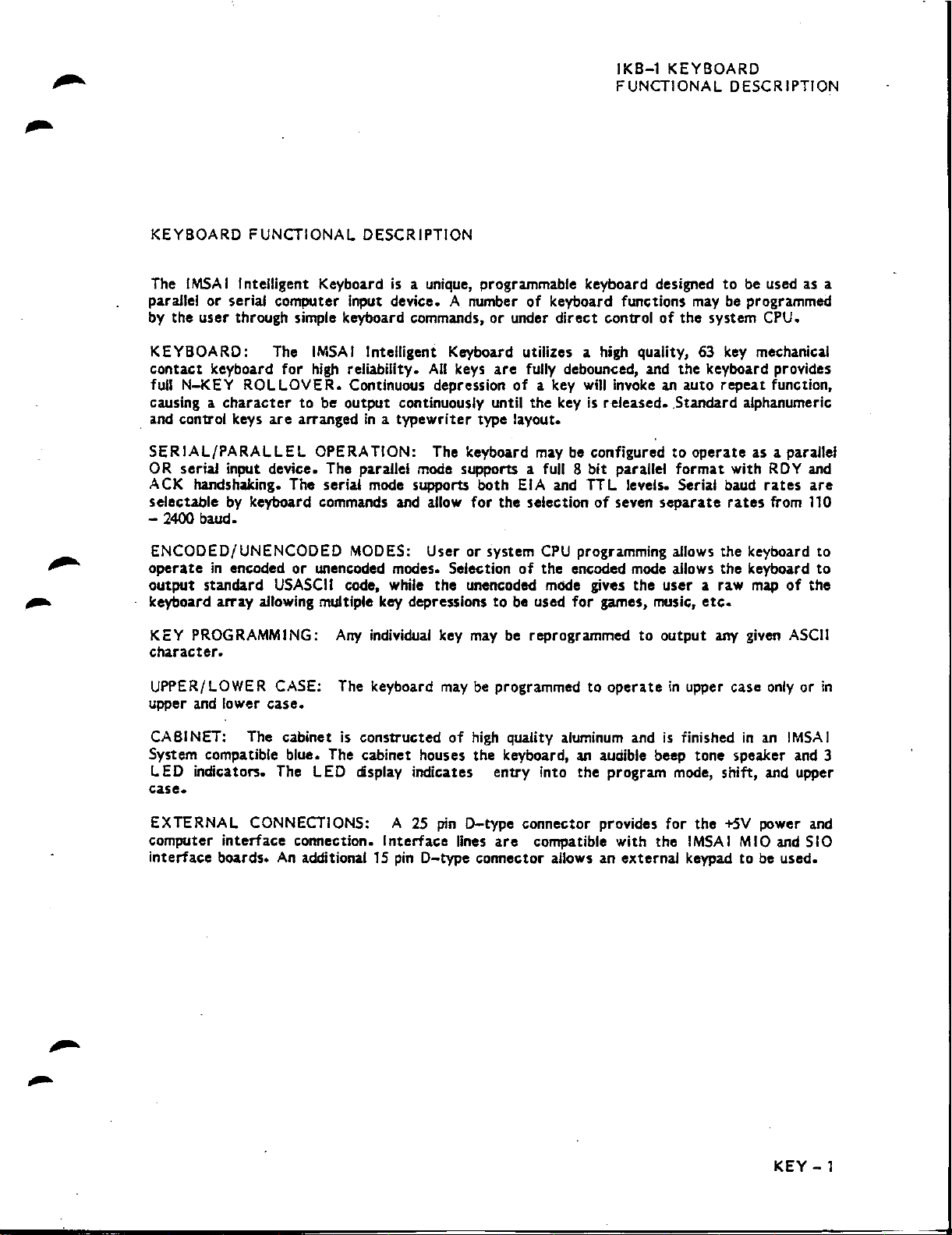
I Intelligent Keyboardisa unique, programmable keyboard designed
parallel or serial computer input device. A number
by
the
user
through simple keyboard commands, or under
IKB-1 KEYBOARD
FUNCTIONAL DESCRIPTION
of
keyboard functions
direct
controlofthe
to
be used as a
may
be programmed
system CPU.
KEYBOARD: The
contact
full N-KEY
causing a
. and control keys
SERIAL/PARALLEL
OR serial input device. The parallel
ACK
selectable
- 2400 baud.
ENCODED/UNENCODED MODES: User
operateinencodedorunencoded modes. Selectionofthe encoded
output
keyboard array
KEY PROGRAMMING:
character.
UPPER/LOWER CASE: The keyboard
upper and lower
CABINET: The cabinet is constructedofhigh
System compatible blue. The cabinet houses the keyboard,anaudible beep tone speaker and 3
ED
L
keyboard
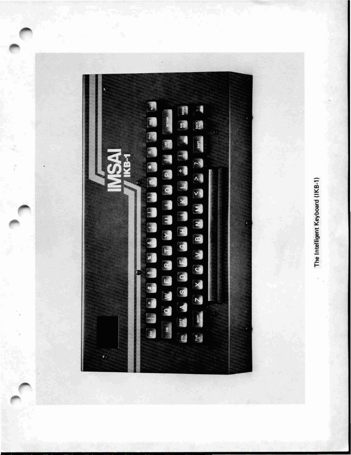
ROLLOVER.
character
handshaking. The serial
by
keyboard commands and allow
standard
allowing multiple key depressionstobe used
indicators. The L
IMSAI
for
high
to
are
arrangedina
USASCII
case.
Intelligent Keyboard utilizes a high quality, 63
reliability.
Continuous depressionofa key
be
output
OPERATION: The keyboard
mode
code, while
Arty
individual key
ED
display indicates entry into the program mode, shift, and upper
All
keys
are
fully debounced, and
will
invokeanauto
continuously until the keyisreleased•.Standard alphanumeric
typewriter
mode
supports both EIA and
type layout.
may
be configuredtooperate
supports a full 8 bit parallel
TIL
levels. Serial baud
for
the
selectionofseven
or
system
the
unencoded mode gives the
may
may
be programmedtooperateinupper case
CPU
programming allows the keyboard to
for
games, music,
be reprogrammedtooutput
quality aluminum andisfinishedinan
separate
mode
user
format
allows the keyboard
key
the
keyboard provides
repeat
with
rates
a raw
etc.
arty
mechanical
function,
as a parallel
RDY
rates
from 110
mapofthe
given
ASCII
onlyorin
IMSAI
case.
and
are
to
-
EXTERNAL CONNECTIONS: A
computer
interface boards.
interface
connection.
An
additional 1
Interface
Spin
2S
pin
D-type connector provides
lines
are
compatible with the
D-type connector allows an external keypad to be used.
for
the
IMSAI
+5V
,1,110
power and
and SIO
KEY
-1

LTR
REVISIONS
DESCRIPTION
o
ORIGINAL
REV. 1
APPROVED
I
"00
•
),....
~f*fJ.
~
~<~
(((Il~\
.....
....
.
~r?
Jj
~11
:[1~,~~e:::
1
--
.=
.~~
'!fJjI~J
•
J J
11.0
"
..
liillrr:
lrrr~lJ~111
•
Ii
I.
I"
1
:'/JI
I'
I~/
\
';1,'1
'"
-c;
,~https://manualmachine.com/
..
11:1
~'II'
~I''~JJl
it'
/'
~
I
L
_
..
~'i
\6'·t
:'~,~
/e~
1((
i /
l~l
l6·-
6>\
/"
f:>
B"',~~
f\1:..
II
jt./
1
:
'.:
-
1
J.
I.
--=:::::..,
~
i
e·(
le·~
",
e-(
e-~
/
"/"
__
B-'_
)I~jl
. .
~'...
----0
:=::.r~-----
e-r
B·~
B"-J'-S"
.~o-'l.
(r;':
1'1:1
';:.:
.'1:'
-
".-
~
~(
B'or)
".'"
i
Ii
I
•
••
II:·
t-.
/'
(M
JJrV(i
~~}jl
@)
- "
e-r
6-T
),
f> _
6'o(
o
(
e
'./
6-(
eor)
e<t·
..B
-,
J]
,J::?':-
:s
:s.~
~"
~i~111
l
'" i
\.""
f
.~--
e
• !
~
-
-~
~o(
u
){
~
6·(
e"(!1-
/,/
e/
e·~
••
---,
__
e·(
e·,
~-~
"-
II
'1'1'1
,I
I,
-,
,
I
I '
I
,~
"",
,
e-tl
e
JJ
/ / !
Ir""6
\,J
,
~·:01
soco,"
"".-J
TOLER~NCES
UNLESS
OTHERWISE SPECIFIED
FRACTIONS DEC. ANGLES MADE
± ± ±
/'
r'
APPROVALSIDATE
DR""
"
HECKEl;>
@
1977
IMSAI
MFG.
CORP
ALL
RIGHTS RESERVED WORLDWIDE
IN
f--=====---------------j
SCALE
U.S.A.
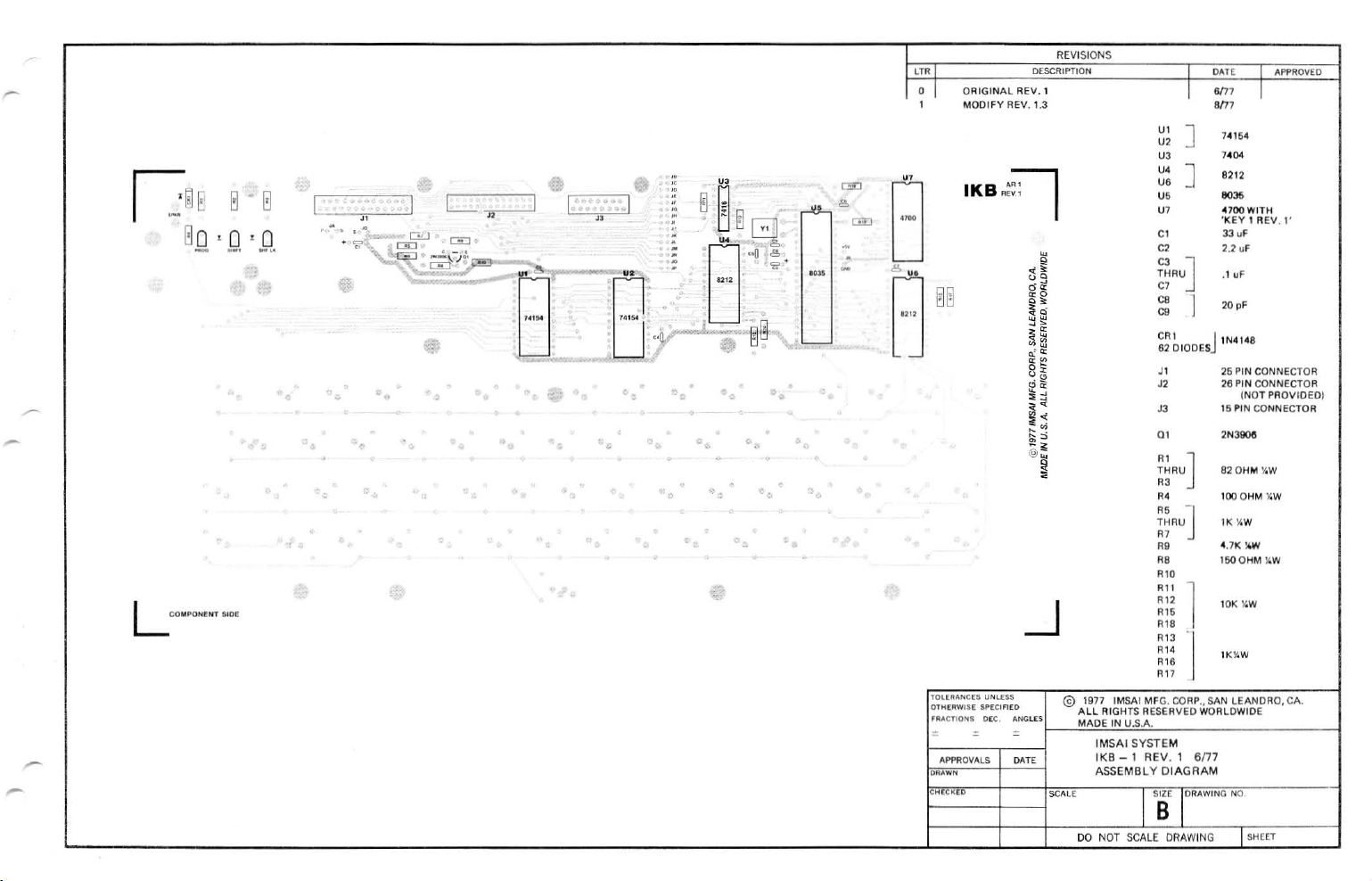
IMSAI SYSTEM
IKB-l
REV.l
DIODE PLACEMENT DIAGRAM
J
DO
NOT
SCALE
.•
SSE
lDRAWING
DRAWINGISHEET1OF
SAN
LEANDRO,
NO
CA.
1
r-
-
,...
REVISIONS
'"
ORIGINAL
o
,
MODIFY
"'
GQ
o. 0
•9,•
.Q.
~~E
~
c--:c-n~
"
"",<"2
•
"
ow
L
eEl
,
-,,------J
'
".
,
.. ..
Ceo':.1
"
-B"~'
"
.'''.y, i
"
.....
•
,
..
.,~
, ,
t.
o
~
,r-;;-l
·m
'B"q
;.m
:,0,
.•
"@8
@ • ,-,
•
.
,
.,
.
.,
v
'i:.
'.
-,-
•
.
•
"
'"
c:EJ 4
~
~
B
."
B
IKB~~
Ii
'.
L
CO"POH~NT
SlOE
lOW'
...
NC(S
OTH(RWIS(
~"'CTlONS::
.-
APPROVALS
DRAWN
ICN~CHD
D£SCRIPTION
REV, 1
REV. 1.3
UI
U,
U3
U'
U6
U'
U7
CI
C,
q~
00
oci.
"0
o.
;~
~~
."
lia:
0%
".
~12
,"
."
••
~.q
~"
~i
@;;;
~
-.J
C3
THRU
C7
C6
eg
CAl J
62 DIODES
JI
J'
J3
0'
THRU
"'
OJ
"'
.,
THRU
R7
R9
R9
'"
'"
."
,,,
."
."
."
."
."
UNlUS @ 1977 IMSAI MFG. CORP.,
$P(Clfl£O
O£C.
:NGl[Sf-
"""
ALL
RIGHTS
__
M"",A,O,'~'"N~UOS,A""
AESERVED
IMSAI SYSTEM
IKB - 1 REV. 1
ASSEMBLY
DIAGRAM
]
J
]
J
]
J
1
I
SAN
WORLDWIDE
6n7
4.7K
1500HM
74154
740'
B212
"35
4700WITH
'KEY1REV,I'
3J
"
2.2
uF
.1
uF
20 "
IN4l"S
25
PIN
CONNECTOR
26
PIN
CONNECTOR
(NOT PROVIDED)
15
PIN
CONNECTOR
2N39Oe
820HM
%W
lOQOHM
%W
IK
%W
%W
lIiW
,OK
I4W
lK%W
LEANDRO, CA.
APPROVED
-;
I I I"'"
SHEET
REVISIONS
nR
o
ORIGINAL
,
REV. 1.3
DESCRIPTION
REV.!
APPROV(D
-
'""'
,..
~
"8---,
@-"
~.
± •
~·+·4"
,
L.....-"-j
L--~L~
L.....-'+
:.
:.--111
~
j
0"
••
0"
",
<.J
~
6_
j
lLq
y-'
__
~,
•
.:1.-;;"!'"
"dB~
~--
h
,"
:-"JJ-
.
7<f----L.,,]-
" ."
. -"
,
-"
~~~
old
r:
..
© 1977 IMSAI MFG.
ALL
RIGHTS RESERVED WORLDWIDE
UA"E
IN~U~.5~.A",-.
" .
APPROVALS
DRAWN
ICH(C~(O
"'"
sCALE
U'
U'
U3
U'
U'
U5
U7
e,
e,
e3
THAU
e7
e.
e,
CAl '11N4148
62
J'
J'
J3
0'
0'
THAU
03
O.
05
THRU
07
0'
O.
0"
0"
0"
0"
0"
0"
0
..
0"
0"
__
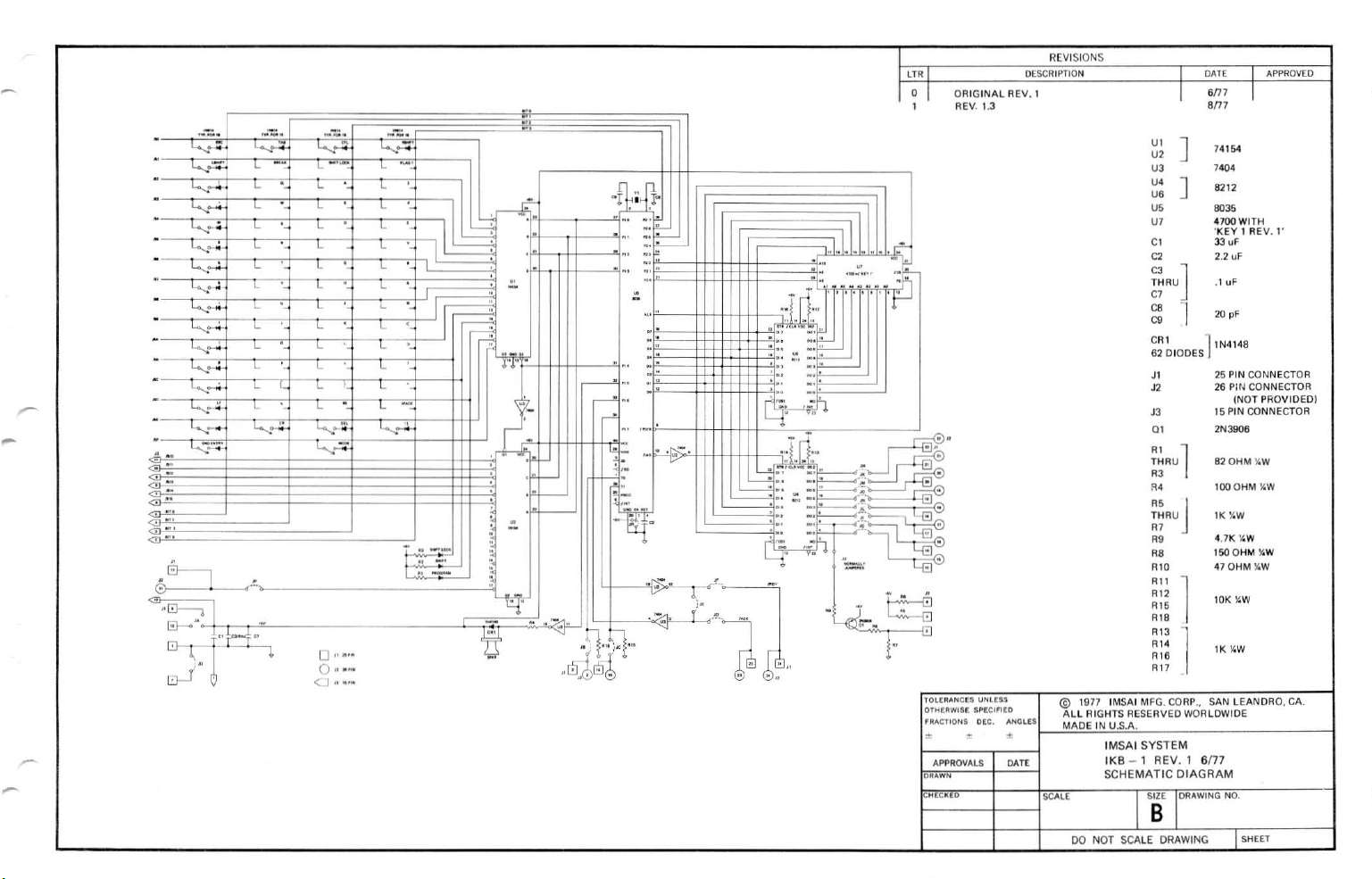
IMSAI SYSTEM
IKB
- 1 REV. 1 6/77
SCHEMATIC DIAGRAM
SIZE )ORAWING NO.
]
]
]
1
DIODES
1
J
-,
"I
CORP"
7.154
"04
8212
6031>
4700
WITH
'KEY 1
REV.l'
33 uF
2.2
uF
.1
uF
20
pF
25 PIN CONNECTOR
26 Pltj CONNECTOR
(NOT PROVIDEDI
15 PIN
CONNECTOR
'NJ906
BlOHM
:<oW
l000HM
%W
IK%W
4.7K
YOW
150QHM
%W
47
OHM
%W
10K
YOW
lK
YOW
SAN LEANDRO, CA.
B
DO
NOT
SCALE
DRAWINGISHEET
IKB-l
ASSEMBLY INSTRUCTIONS
"..
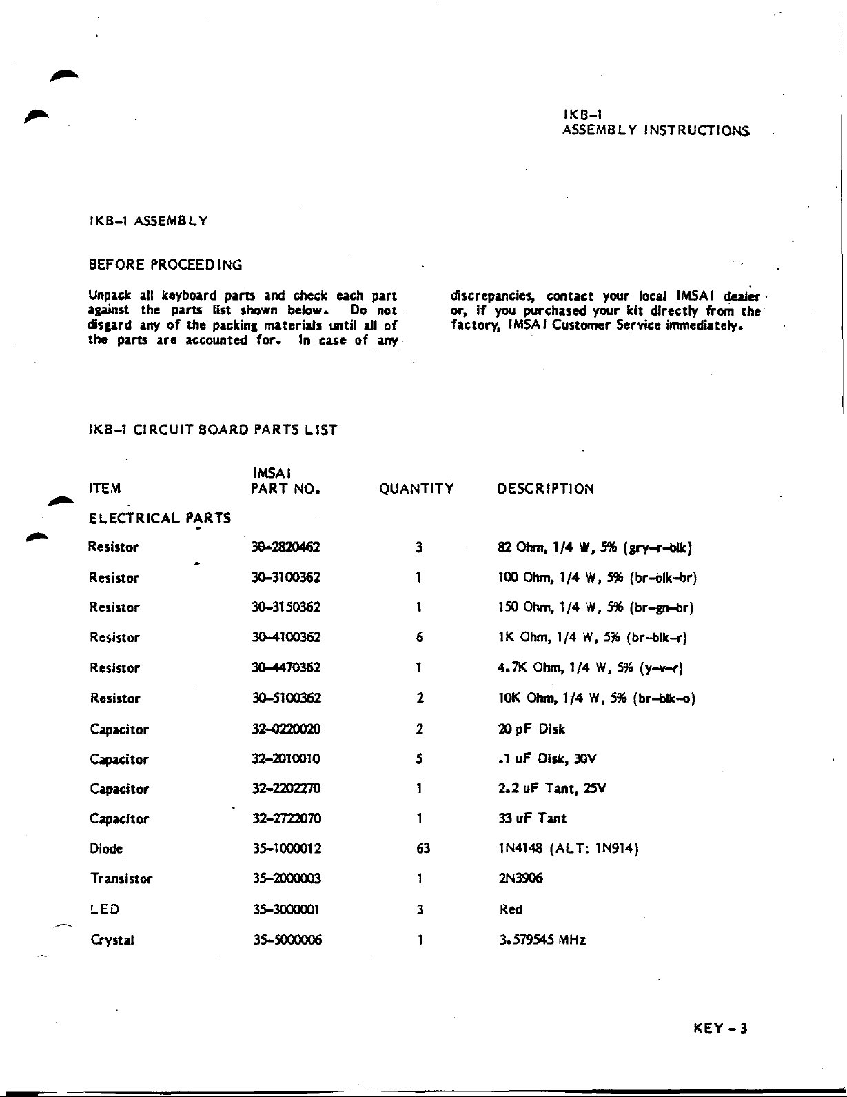
IKB-l
BEFORE PROCEEDING
Unpadc all keyboard parts and check each
against
disgard anyofthe
the
IKB-l
ITEM
.,.,..
ELECTRICAL PARTS
Resistor
Resistor
Resistor 30-3150362 1 150 Ohm,
ASSEMBLY
the
parts
list shown below.
packing
parts
are
accounted
CIRCUIT BOARD PARTS
IMSAI
PART
3&--2820462
30-3100362
materials
for.
In
LIST
NO.
until
case
part
Do
not
all
of
of
any
QUANTITY
discrepancies,
or,
factory,
3
1
conuct
if
you purchased your kit directly
IMSAI
DESCRIPTION
82
100
Customer Service
Ohm,
1/4
Otvn,
1/4
1/4
your local
W,
S%
W,
W,
(gry-r-bllc)
5%
(br-blk-br)
5%
(br-gn-br)
IMSAIdealer·
from
the'
immed~tely.
Resistor
Resistor 30-4470362 1
Resistor 30-5100362
Capacitor 32-0220020 2
Capacitor
Capacitor 32-2202270 1
Capacitor 32-2722070
Diode
Transistor 35-2000003 2N3906
LED
~
Crystal 35-5000006 1
30-4100362
32-2010010
35-1000012
35-?IJOOOOI
6
2
5
1
63
3
lK
Ohm,
1/4
W,
5%
4.71<
Ohm,
1/4
W,
5%
10K
Ohm,1f4
pF
Disk
20
.1 uF Disk,
2.2uFTant,
33uFTant
lN4148 (ALT: lN914)
Red
3.579545
?lJV
MHz
W,
2SV
5%
(br-blk-r)
(y-v-r)
(br-bik-o)
KEY
-3
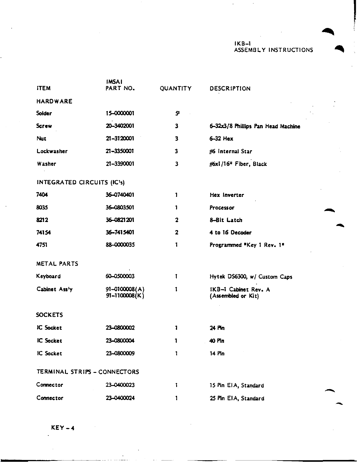
ITEM
HARDWARE
IMSAI
PART
NO.
QUANTITY
IKB-l
ASSEMBLY INSTRUCTIONS
DESCRIPTION
,
~
~
Solder
Screw
Nut
Lockwasher 21-3350001
Washer 21-3390001
INTEGRATED
7404
8035
8212
74154
4751
METAL PARTS
Keyboard
CIRCUITS
IS-OOOOOOl
20-3402001
21-3120001
(ICfs)
36-0740401
36-0803501 1
36-0821201
36-7415401
88-0000035 1
6O-OSOOOO3
5'
3
3
3
3
1
2
2 4to16
1
6-32x3/8 Phillips
6-32
Hex
tI6
Internal
t/6x1/16"
Inverter
Hex
Processor
8-8lt
Programmed "Key 1
Hytek 056300,
Fiber,
Latch
Decoder
Star
Pan
Head Machine
Black
Rev.
wI
Custom Caps
-
-
I"
Cabinet Ass'y
SOCKETS
IC
Socket
IC
Socket
IC
Socket
TERMINAL STRIPS - CONNECTORS
Connector
Connector
KEY
-4
91~100008(A)
91-1100008(K)
~
23-0800004
23-0800009 1 14
~23
23-0400024
1
(Assembled
1
1 40
1
24
15
2S
IKB-l
PIn
Pin
Pin
PinEIA,
PinEIA,
Cabinet Rev. A
orKit)
Standard
Standard
-
-

ITEM
MISCELLANEOUS
IMSAI
PART
NO.
QUANTITY
IKB-l
ASSEMBLY INSTRUCTIONS
DESCRIPTION
-
"
Spacer
Wire
Tape
Speaker
IKB-l
HARDWARE.
Screw
Screw
Hardware
Nut
Lockwasher
CABINET ASSEMBLY PARTS LIST
Set
21-3600002
22~122005
28-0600003
60-0000OO9
20-3200001
20-3916001
21-1100001
21-3120001
21-33SOOOI
3
3"
1
1
6
6
2
6 6-32 Hex, CAD
6
7/16"x1/4"
22AWG, Red
3M
Magic
2
1/2"
jl6-32x1/4" Allen, Button Head, BI. Oxide
jl6-32x1
tI6
Internal
Nylon
Tape,
dia. Quam 24AQ728
1/2"
Star
1/2"
Sq.
Allen, Button Head, BI. Oxide
-
"
METAL PARTS
Cover
Digibezet
Cabinet Bottom 93-4100002
Cabinet Cover 93-4100003
MISCELLANEOUS
Washer
Spacer
Allen Wrench
93-21d0008 1
93-2100007
21-3390001
21-3600005
27-0000001 1
IKB-l
1
1
1
6
9OS-6O
wi
IKB-l
IKB-l
tl6xl/16" Fiber, Black
tl6xl
5/64
Red Polarized
Silkscreen Legend
~ev.
C
Rev. H
1/161Round
Nylon
Filter
KEY
-5
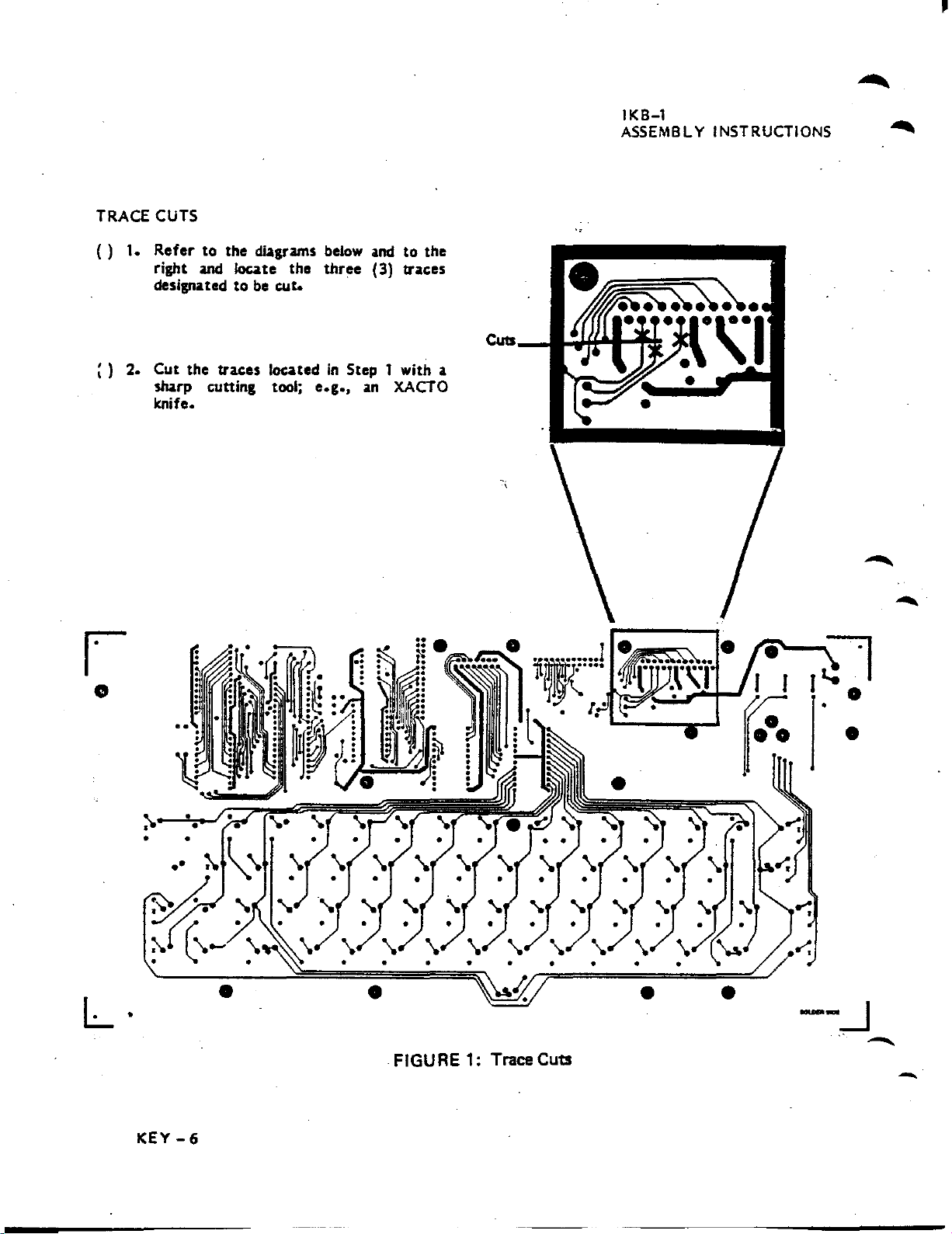
TRACE CUTS
()
1.
Refer
right
designated
;)
2.
Cut
sharp c:uttlng tool;
knife.
to the diagrams below
and
Joute
to
the
trac:es Ioc:atedinStep 1 with a
be
cut.
the
three
e.g.,
and
(3) trac:es
an
to
the
XACTO
IKB-l
ASSEMBLY
INSTRUCTIONS
~
o
L·
:-.
•
•
•
FIGURE 1: Trace Cuts
•
-
•
---.J
-
KEY
-
-6
IKB-I
ASSEMBLY
INSTRUCTIONS
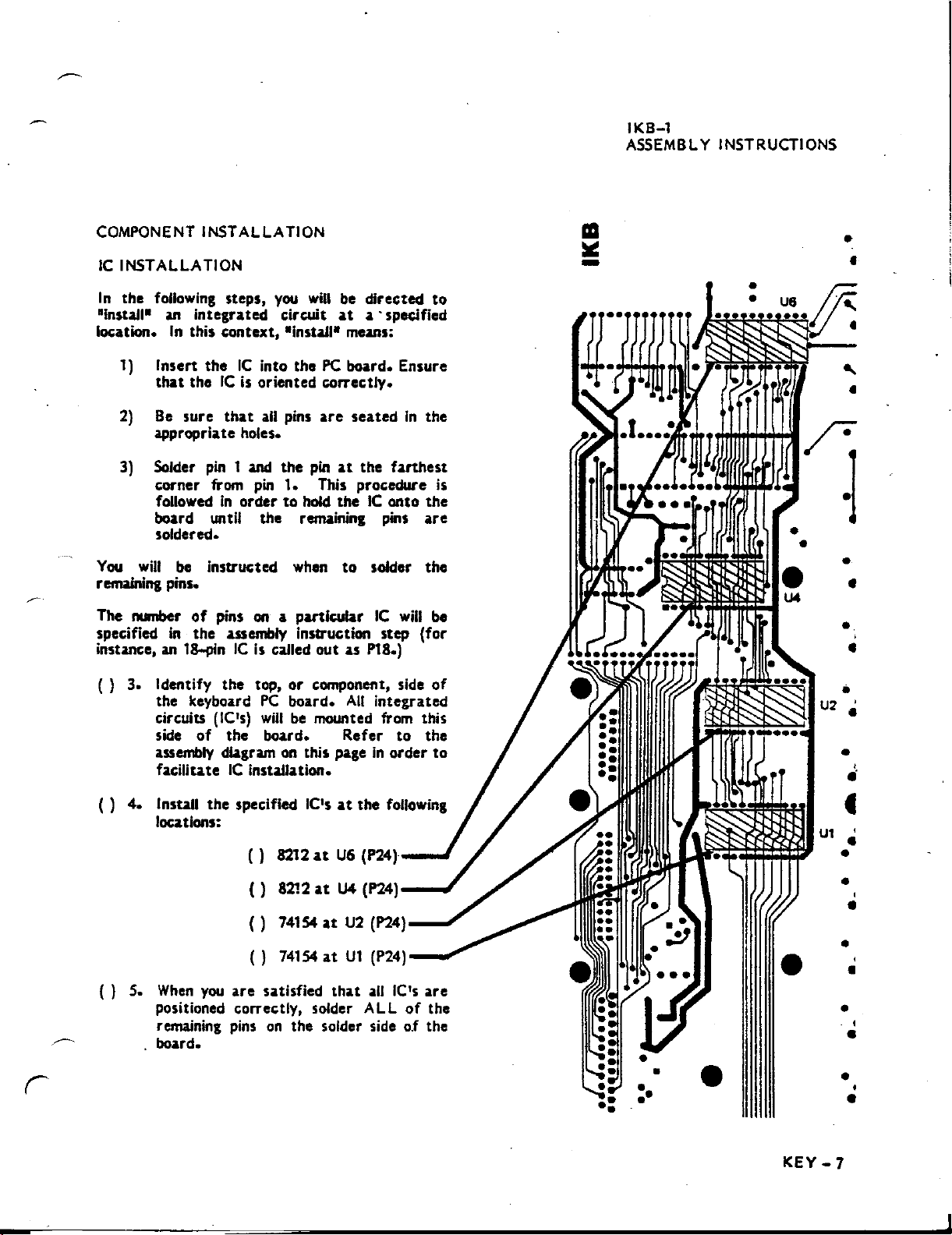
COMPONENT
IC
INSTALLATION
In
the following steps,
"Install"
location.
1)
2)
appropriate holes.
Solder
3)
corner from
board
You
will
remaining pins.
The number
specified
instance,an18-pinICIs
()
3.
()
4.
INSTALLATION
an
integrated circuit
In
this context, "Install" means:
Insen
that
Be
followedinorder
soldered.
Identify the top,
the keyboard
circuits (lC's)
side
assembly
facilitateICinstallation.
Install the specified IC'satthe
locations:
theICinto the
theICis
sure
that
pin
1 and
Wltll
be
instructed when
of
pins on a panlcular
in
the assembly instruction step (for
of
the board. Refer
diagramonthis pageInorder
you
will
be directed
at
a'
specified
PC
board. Ensure
oriented correctly.
all pins
pin
ttle remaining pins
called out as P18.)
PC
willbemounted from this
are
the
pinatthe
I.
This procedure
to
hold the
to
or
component, side
board.
All
seatedInthe
farthest
IC
onto
solder
IC
will
integrated
to
follOWing
to
the
are
the
be
of
the
to
III
~
-
•
•
•
•
-..
•
is
•
•
•
,
•
•
•
__
()
8212atU6
()
8212atU4
()
74154atU2
()
74154atUI
()
S.
When
you
are
satisfied
positioned correctly, solder ALL
pins
on
remaining
board.
the solder side
r
~
,---~~~
(P24)-_
(P24)-_
(P24)-~
(P24)--~
that
all
lC's
of
o.f
are
the
the
••
••
••
·l
••
•
••
•
•
,
•
•
,
•
•
•
KEY-7
•
•
,
•
•
•
•
J
 Loading...