

Page 1

Excellence in Motion
TM
FORCE
MICRO DRIVE
MOTION CONTROL
DRAFT COPY
Hardware
Reference
www.imshome.com
Page 2

TM
Motion Control MForce MicroDrive Hardware Reference Change Log
Date Revision Changes
11/27/2006 R112706 Initial release.
The information in this book has been carefully checked and is believed to be accurate; however, no responsibility is
assumed for inaccuracies.
Intelligent Motion Systems, Inc., reserves the right to make changes without further notice to any products herein to
improve reliability, function or design. Intelligent Motion Systems, Inc., does not assume any liability arising out of the
application or use of any product or circuit described herein; neither does it convey any license under its patent rights of
others. Intelligent Motion Systems and are trademarks of Intelligent Motion Systems, Inc.
Intelligent Motion Systems, Inc.’s general policy does not recommend the use of its products in life support or aircraft
applications wherein a failure or malfunction of the product may directly threaten life or injury. Per Intelligent Motion
Systems, Inc.’s terms and conditions of sales, the user of Intelligent Motion Systems, Inc., products in life support or
aircraft applications assumes all risks of such use and indemnies Intelligent Motion Systems, Inc., against all damages.
Copyright © 2006 Intelligent Motion Systems, Inc., All Rights Reserved
IMS PN MAN-MFIMicro
Revision R112706
Page 3

Table of Contents
Getting Started ..................................................................................................................................1-1
Before You Begin ....................................................................................................................... 1-1
Tools and Equipment Required ................................................................................................. 1-1
Connecting the Power Supply ...................................................................................................1-1
Connecting Communications ...................................................................................................1-1
Connecting the Motor .............................................................................................................. 1-1
Minimum Required Connections .............................................................................................. 1-1
Install IMS Terminal Software ................................................................................................... 1-2
Establishing Communications ................................................................................................... 1-3
Apply Power to the MForce ....................................................................................................... 1-4
Testing the MForce ................................................................................................................... 1-4
Make the MForce Move ............................................................................................................ 1-4
Motion Control Example Using Program Mode ........................................................................ 1-5
Programming Notes ..................................................................................................................1-5
Part 1: Hardware Specification
Section 1.1: Motion Control MForce MicroDrive Product Introduction ............................................1-9
Introduction .............................................................................................................................. 1-9
Feature Summary - Standard and Plus2 Expanded .....................................................................1-9
Section 1.2: Motion Control MForce MicroDrive Detailed Specifications ........................................1-11
Electrical Specifications ........................................................................................................... 1-11
Mechanical Specifications ........................................................................................................ 1-13
Pin/Wire Assignments and Description ................................................................................... 1-13
P1 Connector - I/O and Power Connections ...................................................................... 1-13
P1 Connector Options ....................................................................................................... 1-14
P2 Connector - RS-422/485 Communications................................................................... 1-14
P2 Connector Options ....................................................................................................... 1-15
P3 Connector - Motor Phase Connector ............................................................................ 1-15
P3 Connector ..................................................................................................................... 1-15
Options and Accessories ..........................................................................................................1-16
Section 1.3: MForce MicroDrive Plus2 Expanded Specifications ......................................................1-17
Electrical Specifications ........................................................................................................... 1-17
Mechanical Specifications ........................................................................................................ 1-19
Pin Assignment and Description ............................................................................................. 1-20
P1 Connector - Power and Expanded I/O Configuration ................................................... 1-20
P1 Connector - Power and I/O with Remote Encoder Configuration ................................. 1-20
P1 Connector Options ....................................................................................................... 1-21
P2 Connector - RS-422/485 Communications................................................................... 1-21
P2 Connector Options ....................................................................................................... 1-22
P3 Connector - Motor Phase Connector ............................................................................ 1-22
Options and Accessories ..........................................................................................................1-22
Part 2: Connections and Interface
Section 2.1: Mounting and Connection Recommendations ...............................................................2-3
Mounting Recommendations .................................................................................................... 2-3
DC Power Recommendations ................................................................................................... 2-3
Layout and Interface Guidelines ................................................................................................ 2-3
Recommended Wiring .........................................................................................................2-4
Recommended Mating Connectors and Pins ........................................................................ 2-4
Securing Power Leads and Logic Leads ................................................................................. 2-4
Power Supply Connection .........................................................................................................2-5
Aux-Logic Supply Connection .................................................................................................. 2-6
Section 2.2: Motor Sizing and Selection ............................................................................................2-7
Selecting a Motor ......................................................................................................................2-7
Types and Construction of Stepping Motors ........................................................................ 2-7
Sizing a Motor for Your System ............................................................................................2-7
Recommended IMS Motors ..................................................................................................... 2-8
i
Page 4

IMS Inside Out Stepper Motors ........................................................................................... 2-9
Motor Wiring.......................................................................................................................... 2-10
Connecting the Motor ............................................................................................................ 2-10
8 Lead Motors ................................................................................................................... 2-10
6 Lead Motors .................................................................................................................... 2-11
4 Lead Motors .................................................................................................................... 2-12
Section 2.3: Interfacing Communications .......................................................................................2-13
Available Communications Cables/Converters ........................................................................ 2-13
Interfacing Single Mode Communications .............................................................................. 2-13
Single Mode Communications Full Duplex (RS-422) ........................................................ 2-13
Single Mode Communications Half Duplex (RS-485) ....................................................... 2-14
Interfacing Party Mode Communications ................................................................................ 2-14
Data Cable Termination Resistors ....................................................................................... 2-14
MForce Communication Format ........................................................................................ 2-15
MForce Response to Echo Mode ........................................................................................ 2-15
Using Check Sum ............................................................................................................... 2-17
MForce Party Mode Sample Codes ..................................................................................... 2-18
MForce Immediate Party Mode Sample Codes ................................................................... 2-18
Section 2.4: Interfacing and Using the MFI I/O ...............................................................................2-20
The MForce Digital I/O .......................................................................................................... 2-20
Standard I/O Set ................................................................................................................ 2-20
Enhanced I/O Set - MForce Plus2 Version .......................................................................... 2-20
Uses of the Digital I/O ............................................................................................................ 2-20
MForce Digital Input Functions .............................................................................................. 2-21
Input Functions (I/O Points 1-4, 9-12) .............................................................................. 2-21
Input Functions (Points 7 & 8 — Clock Inputs and Point 13 — Capture) ........................ 2-22
Active States Defined .......................................................................................................... 2-22
MForce Digital Output Functions ........................................................................................... 2-22
Programmable Output Functions ....................................................................................... 2-22
Output Functions (Points 7 & 8 — Clock Outputs and Point 13 — Trip) ......................... 2-23
MForce I/O Ratings ................................................................................................................ 2-24
MForce Standard I/O Connections ......................................................................................... 2-24
MForce Expanded Plus2 I/O Connections ............................................................................... 2-25
I/O Usage Examples — MForce Standard I/O Set ..................................................................2-26
Input Interface Example - Switch Input Example (Sinking Input) ...................................... 2-26
Input Interface Example - Switch Input Example (Sourcing Input) ....................................2-27
Output Interface Example (Sinking Output) ...................................................................... 2-28
General Purpose I/O Usage Examples — Enhanced I/O Set ................................................... 2-29
Input Interface Example - Switch Input Example (Sinking Input) ...................................... 2-29
Input Interface Example - Switch Input Example (Sourcing Input) ....................................2-30
Output Interface Example (Sinking Output) ...................................................................... 2-31
Output Interface Example (Sourcing Output) .................................................................... 2-32
Dedicated Digital I/O - Enhanced I/O Set .............................................................................. 2-33
Step/Direction/Clock I/O ..................................................................................................2-33
Capture/Trip ...................................................................................................................... 2-34
Interfacing the Analog Input ................................................................................................... 2-35
Sample Usage ..................................................................................................................... 2-35
Appendices
Appendix A: Recommended Power and Cable Configurations .......................................................... A-3
Example A – Cabling Under 50 Feet, DC Power .......................................................................A-3
Example B – Cabling 50 Feet or Greater, AC Power to Full Wave Bridge ..................................A-3
Example C – Cabling 50 Feet or Greater, AC Power to Power Supply .......................................A-3
Recommended IMS Power Supplies .......................................................................................... A-4
Recommended Power Supply Cabling .......................................................................................A-4
Appendix B: I/O Application Guide .................................................................................................. A-5
Standard I/O Set Interfacing and Application ............................................................................A-5
NPN Sinking Input ..............................................................................................................A-5
PNP Sourcing Input .............................................................................................................A-6
Sinking Output ....................................................................................................................A-7
ii
Page 5

Mixed Input/Output Example ..............................................................................................A-7
Enhanced I/O Set Interfacing and Application ..........................................................................A-8
NPN Sinking Input ..............................................................................................................A-8
PNP Sourcing Input .............................................................................................................A-8
Sourcing Output ..................................................................................................................A-8
Mixed Input/Output Example ............................................................................................A-10
Interfacing Inputs as a Group Example....................................................................................A-10
Interfacing Outputs as a Group Example.................................................................................A-11
Appendix C: Encoder Options ......................................................................................................... A-12
MForce Motion Control Closed Loop Options .......................................................................A-12
Remote Differential Encoder - MForce MicroDrive Plus2 ..................................................A-12
Encoders Available from IMS ..................................................................................................A-12
General Specifications ........................................................................................................A-12
Encoder Signals .......................................................................................................................A-13
Differential Encoder ...........................................................................................................A-13
Characteristics ....................................................................................................................A-13
Encoder Cables ......................................................................................................................A-14
Recommended Encoder Mating Connectors ...........................................................................A-14
Appendix D: Optional Cables and Cordsets .................................................................................... A-15
Communications Converter Cables .........................................................................................A-15
USB to 10-Pin IDC (MD-CC400-000) .............................................................................A-15
Electrical Specifications ......................................................................................................A-15
Mechanical Specifications ...................................................................................................A-15
Installation Procedure for the MX-CC40x-000 .......................................................................A-16
Installing the Cable/VCP Drivers .......................................................................................A-16
Determining the Virtual COM Port (VCP) ........................................................................A-18
Prototype Development Cables ...............................................................................................A-18
PD16-1417-FL3 — Power and I/O....................................................................................A-19
Prototype Development Cable PD10-1434-FL3 (All MForce Plus Motion Control) ...............A-20
Setup Instructions — Cable #1 ..........................................................................................A-20
Setup Instructions — Cable #2 and Subsequent MDrives ..................................................A-20
Appendix E: IMS Enhanced Torque Stepping Motors ...................................................................... A-22
Size 14 Enhanced Torque Stepping Motor ...............................................................................A-22
General Specifications ........................................................................................................A-22
Wiring And Connection .....................................................................................................A-22
Mechanical Specifications ...................................................................................................A-22
Size 17 Enhanced Torque Stepping Motor ...............................................................................A-23
General Specifications ........................................................................................................A-23
Wiring And Connection .....................................................................................................A-23
Mechanical Specifications ...................................................................................................A-23
Size 23 Enhanced Torque Stepping Motor ...............................................................................A-24
General Specifications ........................................................................................................A-24
Wiring And Connection .....................................................................................................A-24
Figure GS.1: MForce MicroDrive Minumum Required Connections ........................................ 1-2
Figure GS.2: Product CD Entry and Installation Screens ..........................................................1-2
Figure GS.3: IMS Terminal Main Screen ................................................................................... 1-3
Figure GS.4: IMS Terminal Preferences Dialog .......................................................................... 1-3
Figure GS.5 MForce MicroDrive Sign-On Message................................................................... 1-4
Figure GS.6: Download the Program ........................................................................................ 1-5
Part 1: Hardware Specification
Figure 1.1.1: MForce MicroDrive with 7-Pin Terminal Strip ..................................................... 1-9
Figure 1.1.2: MForce MicroDrive Plus2 with Locking Wire Crimp ........................................... 1-9
Figure 1.2.1: Mechanical Specifications ................................................................................... 1-13
Figure 1.2.2: P1 Wire Color and Pin Assignment .................................................................... 1-14
Figure 1.2.3: P2 Pin Assignment ............................................................................................. 1-15
Figure 1.2.4: P3 — 4-Pin Locking Wire Crimp Motor Connector .......................................... 1-15
List of Figures
iii
Page 6

Figure 1.3.1: Mechanical Specifications ................................................................................... 1-19
Figure 1.3.2: 16-Pin Wire Crimp Connector P1 Pin Numbers ................................................ 1-21
Figure 1.3.3: P2 Pin Assignment ............................................................................................. 1-22
Figure 1.3.4: P3: 4-Pin Locking Wire Crimp Motor Connector .............................................. 1-22
Part 2: Connections and Interface
Figure 2.1.1: MForce MicroDrive Mounting Recommendations ............................................... 2-3
Figure 2.1.2: Grounding and Shielding for Logic Connections .................................................. 2-4
Figure 2.1.3: MForce MicroDrive Power Connections ..............................................................2-5
Figure 2.1.4: Aux-Logic Connection ......................................................................................... 2-6
Figure 2.2.1 A & B: Per Phase Winding Inductance .................................................................. 2-8
Figure 2.2.2: 8 Lead Motor Series Connections ....................................................................... 2-10
Figure 2.2.3: 8 Lead Motor Parallel Connections.................................................................... 2-11
Figure 2.2.4: 6 Lead Half Coil (Higher Speed) Motor Connections ....................................... 2-11
Figure 2.2.5: 6 Lead Full Coil (Higher Torque) Motor Connections ...................................... 2-12
Figure 2.2.6: 4 Lead Motor Connections ................................................................................. 2-12
Figure 2.3.1: Full Duplex Communications (RS-422) ............................................................. 2-13
Figure 2.3.2: Half Duplex 2 Wire Communications (RS-485) ................................................2-14
Figure 2.3.3: RS-485 Interface, Multiple MForce System ........................................................ 2-15
Figure 2.4.1: Uses for the Digital I/O ...................................................................................... 2-20
Figure 2.4.2: Flying Lead I/O Connections ............................................................................. 2-24
Figure 2.4.3: 7-Pin Pluggable Terminal I/O Connections ........................................................ 2-24
Figure 2.4.4: Plus 2 I/O Connections - Expanded I/O Configuration ..................................... 2-25
Figure 2.4.5: Plus 2 I/O Connections - Closed Loop Configuration ........................................ 2-25
Figure 2.4.6: Sinking Input Example using a Push Button Switch ........................................... 2-26
Figure 2.4.7: Sourcing Input Example using a Push Button Switch ......................................... 2-27
Figure 2.4.8: Sinking Output Example .................................................................................... 2-28
Figure 2.4.9: Switch Interface to Input, Sinking ...................................................................... 2-29
Figure 2.4.10 Sourcing Input Example using a Push Button Switch ........................................ 2-30
Figure 2.4.11: Sinking Output Example .................................................................................. 2-31
Figure 2.4.12: Sourcing Output Example ................................................................................2-32
Figure 2.4.13: MFI Clock Functions ....................................................................................... 2-33
Figure 2.4.14: Step Direction I/O Equivalent Circuit .............................................................. 2-33
Figure 2.4.15: Capture/Trip I/O Equivalent Circuit ................................................................ 2-34
Figure 2.4.16: Analog Input - Voltage Mode ........................................................................... 2-35
Figure 2.4.17: Analog Input - Current Mode .......................................................................... 2-36
iv
Appendices
Figure A.1: DC Cabling - Under 50 Feet...................................................................................A-3
Figure A.2: DC Cabling - 50 Feet or Greater - AC To Full Wave Bridge Rectifier ......................A-3
Figure A.3: AC Cabling - 50 Feet or Greater - AC To Power Supply ..........................................A-3
Figure B.1: NPN Interface to an MDI Sinking Input ................................................................A-5
Figure B.2: PNP Interface to a Sourcing Input ..........................................................................A-6
Figure B.3: Sinking Output to Relay .........................................................................................A-7
Figure B.4: Mixed Output Example- Standard I/O Set ..............................................................A-7
Figure B.5: NPN Sinking Input on an MForce Plus2 Motion Control .....................................A-8
Figure B.6: PNP Sourcing Input on an MForce Plus2 Motion Control .....................................A-8
Figure B.7: Sourcing Output to Sourcing Input ........................................................................A-9
Figure B.8: Mixed Input/Output Example - Enhanced I/O .....................................................A-10
Figure B.9: TTL Interface to an Input Group ..........................................................................A-10
Figure B.10: Outputs Interfaced to LED’s as a Group .............................................................A-11
Figure C.1: Connecting a Remote Encoder .............................................................................A-12
Figure C.2: Differential Encoder Signals ..................................................................................A-13
Figure D.1: MD-CC400-000 ..................................................................................................A-15
Figure D.2: MD-CC400-000 Mechanical Specifications .........................................................A-15
Figure D.3: Hardware Update Wizard ..................................................................................... A-16
Figure D.4: Hardware Update Wizard Screen 2 .......................................................................A-16
Figure D.5: Hardware Update Wizard Screen 3 .......................................................................A-17
Figure D.6: Windows Logo Compatibility Testing ..................................................................A-17
Figure D.7: Hardware Update Wizard Finish Installation ........................................................A-17
Figure D.8: Hardware Properties ............................................................................................. A-18
Figure D.9: Windows Device Manager .................................................................................... A-18
Figure D.10: PD16-1417-FL3 Prototype Development Cable ................................................A-19
Figure D.11: PD10-1434-FL3 ................................................................................................A-21
Figure E.1: Size 14 Wiring and Connection ............................................................................A-22
Figure E.2: Size 14 Mechanical Specifications ..........................................................................A-22
Page 7

Table GS.1: Minimum Required Connections .......................................................................... 1-1
Part 1: Hardware Specification
Table 1.2.1: P1 — Pin Assignment, Power and I/O ................................................................. 1-13
Table 1.2.2: P2 — Pin Assignment, RS-422/485 Communications......................................... 1-14
Table 1.2.3: P3 — Pin Assignment, Motor Phase Connections ............................................... 1-15
Table 1.3.1: P1 — Pin Assignment, Expanded I/O Configuration .......................................... 1-20
Table 1.3.2: P1 — Pin Assignment, Remote Encoder Configuration ....................................... 1-20
Table 1.3.3: P2 — Pin Assignment, RS-422/485 Communications......................................... 1-21
Table 1.3.4: P3 — Pin Assignment, Motor Phase Connections ............................................... 1-22
Part 2: Connections and Interface
Table 2.3.1: MForce Response to Echo Mode - Party and Check Sum are Zero (0) ................. 2-16
Table 2.3.2: MForce Response to Echo Mode - Party is One (1) and Check Sum is Zero (0) .. 2-16
Table 2.3.3: MForce Response to Echo Mode - Party is Zero (0) and Check Sum is One (1) .. 2-16
Table 2.3.4: MForce Response to Echo Mode - Party and Check Sum are One (1) ................. 2-17
Table 2.4.1: Programmable Input Functions............................................................................ 2-21
Table 2.4.2: Dedicated Input Functions ..................................................................................2-22
Table 2.4.3: Programmable Output Functions ........................................................................ 2-23
Table 2.4.4: Dedicated Output Functions ...............................................................................2-23
Table 2.3.5: MForce I/O and Protection Ratings ..................................................................... 2-24
Appendices
Table A.1: Recommended Supply Cables ..................................................................................A-4
Table B.1: Output Bit Weight Examples - Outputs set as a group ...........................................A-11
Table C.1: Available Encoder Line Counts, Part Numbers and Pin Configurations .................A-12
Table D.1: MD-CC400-000 Electrical Specifications ..............................................................A-15
Table D.2: PD16-1417-FL3 Wire Color Codes.......................................................................A-19
Table D.3: PD10-1434-FL3 Wire Color Codes.......................................................................A-20
Table E.1: Size 14 General Specifications .................................................................................A-22
Table E.2: Size 17 General Specifications .................................................................................A-23
Table E.3: Size 23 General Specifications .................................................................................A-24
List of Tables
v
Page 8

Page Intentionally Left Blank
vi
Page 9

Ge t ti n g S ta r te d
Getting Started
Before You Begin
A printed Quick Reference guide designed to help get you connected and communicating with the MForce is
shipped with your product. The following examples will help you get the motor turning for the first time and introduce you to Immediate and Program modes of operation.
Immediate Mode: In Immediate Mode, commands are issued and executed directly to the MForce
MicroDrive by user input into the terminal window of the IMS Terminal Program, shown later in this
section.
Program Mode: Program mode is used to input user programs into the Motion Control MForce
MicroDrive .
Tools and Equipment Required
• Motion Control MForce MicroDrive.
• NEMA Size 14, 17 or 23 frame stepping motor.
• Communications Converter Cable IMS P/N MD-CC400-000 or equivalent (USB to RS-422).
• Product CD or internet access to www.imshome.com.
• A +12 to +48 VDC unregulated power supply.
• Basic tools: wire cutters / strippers / screwdriver.
• 20 AWG wire for power supply.
• 20 AWG wire for motor or optional prototype development cable IMS P/N PD04-MF17-FL3.
• A PC with Windows XP Service Pack 2.
• A free serial communications or USB port.
WARNING! Please
ensure that you
read the sections
of the product
manual pertaining to the
MForce MicroDrive model you
purchased in their entirety
prior to placing the unit into full
operation.
Connecting the Power Supply
Using 20 AWG wire, connect the DC output of the power supply to the +V input of the MForce MicroDrive.
Connect the power supply ground to the Power Ground pin appropriate for your MForce MicroDrive. See Figure
GS.1.
Connecting Communications
Connect the Host PC to the Motion Control MForce MicroDrive using the IMS Communications Converter
Cable MD-CC400-000 or equivalent.
See Figure GS-1.
Connecting the Motor
In accordance with the motor manufacturer documentation, connect the Motor Phases to the MForce MicroDrive
Connector P4 (Prototype Development Cable IMS P/N PD04-MF17-FL3 recommended).
See Figure GS.1.
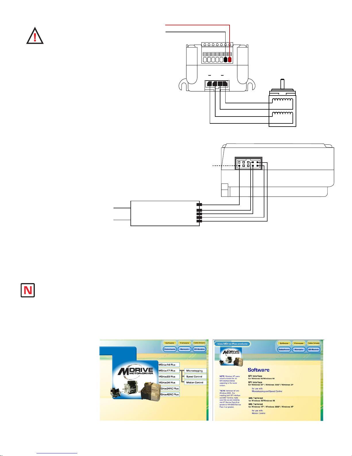
Minumum Required Connections
The following Table and Diagram illustrate the minimum required connections to operate the MForce MicroDrive.
Minumum Required Connections
Connector P1 Flying Leads 7-Pin Termnal 16-Pin Wire Crimp
+12 to +48 VDC Red Pin 7 Pin 15
Power Ground Black Pin 6 Pin 16
Connector P2 10 Pin IDC 10 Pin Wire Crimp
TX+ Pin 1 Pin 9
TX – Pin 2 Pin 10
RX + Pin 3 Pin 7
RX - Pin 4 Pin 8
COMM GND Pin 10 Pin 2
Connector P4 4-Pin Locking Wire Crimp
Motor Phase A Pin 1
Motor Phase A Pin 2
Motor Phase B Pin 3
Motor Phase B Pin 4
Table GS.1: Minimum Required Connections
Part 1: Hardware Specifications
1-1
Page 10
W A R N I N G :
P3
P1
1 2 3 4
+V (+12 to +48 VDC)
+V Return (Ground)
7-Pin Terminal Connector shown
at P1 - Power and I/O interface.
Other Connector Pin Assignments
detailed with product specifications.
ØA
ØBØA ØB
MForce MicroDrive (Front View)
Stepping Motor
Motor Interface Cable
IMS P/N PD04-MF17-FL3
MForce MicroDrive (Side View)
P2
RS-422
Converter
COMM GND
COMM GND
TX+RX+
TX-
RX-
RX+
RX-
TX+
TX-
Host PC
USB/Serial Port
10-Pin IDC Connector shown at P2 Communications Interface. Other
connector pin assignments are
detailed with product specifications.
COMM GND is ONLY
to be used for grounding
communications. Grounding
Aux-Logic or any other
device to COMM GND may
damage the MForce!
Communications Cable
IMS P/N MD-CC400-000
or equivalent
Do not connect
or disconnect
the MForce MicroDrive
with power applied!
Disconnect the AC power
side to power down the DC
Supply.
For battery operated
systems, conditioning
measures should be taken
to prevent device damage
caused by in-rush current
draws, transient arcs and
high voltage spikes.
DC input to
Install IMS Terminal Software
IMS Terminal is an integrated ASCII text editor and terminal emulator designed to easily communicate with and
program IMS Motion Control products. Using this freely provided program will eliminate the added complication
Note: Interactive
Tutorials covering
use of the IMS Terminal are
located on the IMS Web Site
at http://www.imshome.com/
tutorials.html.
1-2
the installation and
of configuring and using a separate text editor and terminal software.
1. Insert the CD included with the product into the CD Drive of your PC.
If not available, go to http://www.imshome.com/software_interfaces.html.
2. The CD will autostart.
3. Click the Software Button in the top-right navigation Area.
4. Click the IMS Terminal link appropriate to your operating system.
5. Click SETUP in the Setup dialog box and follow the on-screen instructions.
6. Once IMS Terminal is installed, the Communications Settings can be checked and/or set.
Figure GS.1: MForce MicroDrive Minimum Required Connections
Figure GS.2: Product CD Entry and Installation Screens
Motion Control MForce MicroDrive Hardware Manual Revision R112706
Page 11

Establishing Communications
1. Open IMS Terminal by clicking Start>Programs>IMS Terminal>IMS Term. The Program Edit
Window (left) and Terminal Window (right) will be displayed.
Figure GS.3: IMS Terminal Main Screen
Note: Entering
MForce MicroDrive
commands directly
into the Terminal Window is
called “Immediate Mode”.
The Motion Control MForce
MicroDrive command set is
not case sensitive except for
command DN = < >
Warning: If you
have installed the
MForce MicroDrive
to a load, be sure
the load can safely be moved
before testing.
Tip: A small piece of tape on
the motor shaft is a visual aid
to help see the shaft turning.
2. On the Menu Bar click Edit / Preferences to open the Preferences dialog box.
3. Click on the Comm Settings tab to open the Comm Settings page.
a. Set Scroll Back to desired range of text lines to be displayed.
b. Under Device, confirm MDrive has been selected and also verify the Comm Port being
used. Do not change any other settings. Click “OK”.
Figure GS.4: IMS Terminal Preferences Dialog
Part 1: Hardware Specifications
1-3
Page 12

Apply Power to the Motion Control MForce MicroDrive
1. Verify that all connections have been made, then apply power to the Motion Control MForce
MicroDrive. Click on the Phone icon or the Disconnect status box to establish communications
between IMS Terminal and the MForce MicroDrive. The following sign-on message should appear
in the Terminal Window:
“Copyright 2001-2006 by Intelligent Motion Systems, Inc.”
2. If you can see the sign-on message, then the MForce MicroDrive is properly powered-up and
communicating.
a. If the sign-on message does not appear, try using a software reset. Hold down the “Ctrl” key
and press “C”. If the sign-on message still does not appear, check all connections, as well as all
hardware and software configurations, then start IMS Terminal again.
3. You are now connected and communicating to the Motion Control MForce MicroDrive.
Note: There are indicators at the bottom of the Terminal Window that show whether you are
connected or disconnected, the current Baud Rate, and the type of device (MDrive displayed
when using MForce) for which the IMS Terminal is configured. These three items may be changed
directly from this screen by double clicking on each of them.
Testing the Motion Control MForce MicroDrive
1. Click in the Terminal Window, and type (followed by ENTER):
PR VM
2. The Motion Control MForce MicroDrive will return a value of 768000
3. Type the following in the Terminal Window (followed by ENTER):
VM=360000
PR VM
4. The Motion Control MForce MicroDrive will return a value of 360000
5. Type FD and press ENTER. (FD = Factory Defaults)
“Copyright 2001-2006 by Intelligent Motion Systems, Inc.”
should appear in the Terminal Window within a few seconds.
Figure GS.5 Motion Control MForce MicroDrive Sign-On Message
Make the Motion Control MForce MicroDrive Move
1. Type MR 51200 into the Terminal Window and press ENTER. (MR = Move Relative)
a. With the default settings, the MForce Motion Control should move one revolution in
approximately 0.066 seconds, or at a velocity of 15 revolutions per second.
2. Type SL 102400 and press ENTER. (SL = Slew)
a. With the default settings, the Motion Control MForce MicroDrive should run constantly at a
speed of approximately 2 revolutions per second or 120 revolutions per minute.
3. Type SL 0 and press ENTER. The Motion Control MForce MicroDrive should decelerate to a full
stop.
1-4
Motion Control MForce MicroDrive Hardware Manual Revision R112706
Page 13
Motion Control Example Using Program Mode
1. Click on drop-down menu View > New Edit Window to open the Program Edit Window.
2. Type “XYZ Test” into the “Open a New file for editing” dialog box, and click “OK”.
3. Click anywhere within the Program Edit Window, and type (followed by ENTER):
VA LP=0 ‘user variable name LP = start count 0
A=100000 ‘set acceleration to 100000 steps/sec
D=100000 ‘set deceleration to 100000 steps/sec
PG 1 ‘enter program mode, start program at address 1
LB AA ‘label program AA
MR 250000 ‘move motor 250000 steps in the positive direction
H ‘hold program execution until motion completes
H 1000 ‘hold 1000 milliseconds
MR –250000 ‘move motor 250000 steps in the negative direction
H ‘hold program execution until motion completes
H 1000 ‘hold 1000 milliseconds
IC LP ‘increment user variable LP
PR ” LP=”,LP; ‘print axis position, 4 characters used, the
‘terminal will display LP=1 LP=2 LP=3
BR AA, LP<3 ‘branch to process label AA, if user variable LP< 3
E ‘end program execution
PG ‘exit program, return to immediate mode
4. Type FD in the Terminal Window and press ENTER to clear the MDrive buffer to factory
defaults before downloading any program.
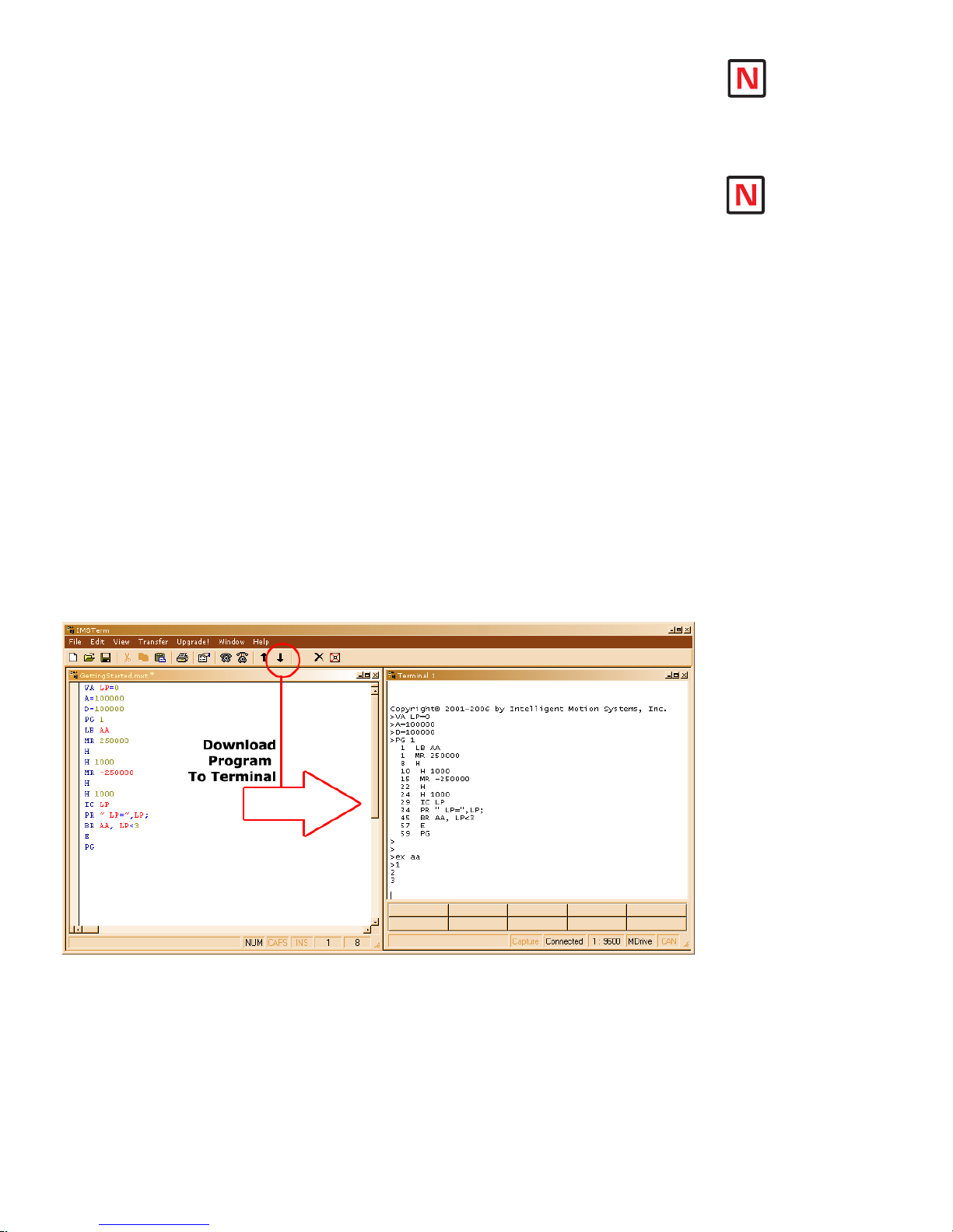
5. Click on drop-down menu Transfer > Download to transfer the program from the Program
Edit Window to the Terminal Window. (Under “Source Type” choose “Edit Window”.)
6. Type EX 1 in the Terminal Window and press ENTER to execute the program.
(EX = Execute at address 1.)
7. The Motion Control MForce MicroDrive will turn the motor 250,000 microsteps in a clockwise
direction, accelerating at 100,000 microsteps per sec2, then decelerating at 100,000 microsteps per
sec2, pausing for 1000 milliseconds, then reversing the sequence in a counterclockwise direction,
repeating the motion cycle 3 times until the program ends.
NOTE: Entering
MForce MicroDrive
commands into
Window, to be edited and
saved, is called “Program
Mode”.
2
2
Button or by pressing Ctrl+C.
the Program Edit
NOTE: The program
can be stopped by
pressing the Escape
Figure GS.6: Download the Program
Programming Notes
The example above demonstrates basic commands that verify that your Motion Control MForce MicroDrive
is communicating with your PC. More complex commands and movement may require that your I/O and/or
Analog Input be interfaced and configured. Refer to the Programming and Software Reference for details.
For more information on Programming and Command Control Sets, refer to the Programming and Software Reference Manual available on the your product CD or via the IMS web site at http://www.imshome.
com/manuals.html.
Part 1: Hardware Specifications
1-5
Page 14

This Page Intentionally Left Blank
Page 15

Part 1:
TM
FORCE
MICRO DRIVE
MOTION CONTROL
Hardware
Excellence in Motion
TM
Specifications
Section 1.1: Product Introduction
Section 1.2: Standard Specifications
Section 1.3: Expanded Plus2 Specifications
Page 16

Page Intentionally Left Blank
1-8
Motion Control MForce MicroDrive Hardware Manual Revision R112706
Page 17

Se c ti o n 1 .1
Product Introduction
Introduction
The Motion Control MForce MicroDrive offers system
designers a low cost, intelligent motion controller integrated
with a +12 to +48 volt/2A RMS Output Current microstepping drive and Motion Controller.
The unsurpassed smoothness and performance delivered
by the Motion Control MForce MicroDrive are achieved
through IMS's advanced 2nd generation current control.
By applying innovative techniques to control current flow
through the motor, resonance is significantly dampened over
the entire speed range and audible noise is reduced.
The MForce MicroDrive accepts a broad input voltage range
from +12 to +48 VDC, delivering enhanced performance and
speed. Oversized input capacitors are used to minimize power
line surges, reducing problems that can occur with long runs
and multiple drive systems. An extended operating range of
–40° to +85°C provides long life, trouble free service in demanding environments.
Standard features available in the MForce MicroDrive include four +5 to +24 volt general purpose I/O lines, one
10 bit analog input, 0 to 5MHz step clock rate, 20 microstep resolutions up to 51,200 steps per revolution, and full
featured easy-to-program instruction set.
Expanded features in the MForce MicroDrive Plus2 version
include eight +5 to +24 volt general purpose I/O lines and the
capability of electronic gearing by following a rotary or linear axis
at an electronically controlled ratio, or an output clock can be
generated fixed to the internal step clock.
MForce MicroDrive Plus2 models are available with optional
closed loop control. This increases functionality by adding stall
detection, position maintenance and find index mark. The closed
loop configuration offers an expanded choice of line counts and
resolutions by interfacing to a remotely mounted user-supplied
external encoder.
The Motion Control MForce MicroDrive communicate over
RS-422/485 which allows for point-to-point or multiple unit
configurations utilizing one communication port. Addressing and
hardware support up to 62 uniquely addressed units communicating over a single line. Baud rate is selectable from 4.8 to 115.2kbps.
Power and signal interface connections are accomplished using 12.0” (30.5cm) flying leads or a 7 position terminal
strip. Plus2 versions interface using a pluggable locking wire crimp connector. Motor phases are connected via a
pluggable 4-pin locking wire crimp connector.
The MForce MicroDrive is a compact, powerful and inexpensive solution that will reduce system cost, design and
assembly time for a large range of applications.
Figure 1.1.1: MForce MicroDrive With 1-Pin
Terminal Strip
Figure 1.1.2: MForce MicroDrive Plus2
Wire Crimp
Note: The Motion
Control MForce
MicroDrive
is available with CAN
communications. For more
information see IMS Web
Site at www.imshome.com.
Feature Summary – Standard and Plus2 Expanded
Standar d Features
Highly Integrated Microstepping Driver and Motion Controller
Advanced 2nd Generation Current Control for Exceptional Performance and Smoothness
Single Supply: +12 to +48 VDC
Compact Size: 1.7 x 2.3 x 1.3 inches (42 x 59 x 1.3 mm)
2A RMS/2.8 A Peak (per phase) Output Current
Low Cost
Extremely Compact
Auxiliary Logic Power Supply Input
20 Microstep Resolutions up to 51,200 Steps Per Rev Including: Degrees, Metric, Arc Minutes
Part 1: Hardware Specifications
1-9
Page 18

Open or Closed Loop Control
Programmable Motor Run and Hold Currents
Four +5 to +24 VDC I/O Lines Accept Sourcing or Sinking Outputs
One 10 Bit Analog Input Selectable: 0 to
+10 VDC, 0 to +5 VDC, 0-20 mA, 4-20 mA
0 to 5MHz Step Clock Rate Selectable in 0.59Hz Increments
RS-422/485 Communications (Optional CANopen dtails available at www.imshome.com)
62 Software Addresses for Multi-Drop Communications
Simple 1 to 2 Character Instructions
Interface Options:
- 12.0” (30.5cm) Flying Leads
- 7-Pin Pluggable Terminal
Expanded Features – Available only in the Plus2 Version
+5 to +24 VDC Tolerant
8 I/O Points with Electronic Gearing (or)
4 I/O Points with External/Remote Encoder for Closed Loop Control
Sourcing or Sinking, Inputs and Outputs:
High Speed Position Capture Input or Trip Output
Pluggable Locking Wire Crimp Interface
1-10
Motion Control MForce MicroDrive Hardware Manual Revision R112706
Page 19

SE C TI O N 1 .2
Motion Control MForce MicroDrive Specifications
Standard Electrical Specifications
Electrical Specifications
Input Voltage (+V) Range* +12 to +48 VDC
Max Power Supply Current (Per MForce MicroDrive)* 2 Amps
Aux-Logic Input Voltage** +12 to +24 VDC
* Actual Power Supply Current will depend on Voltage and Load.
** Maintains power to control and feedback circuits [only] when input voltage is removed
Output Current
Output Current RMS 2 Amps
Output Current Peak (Per Phase) 2.8 Amps
Environmental Specifications
Heat Sink Temperature -40°C to +85°C
I/O Specifications
General Purpose I/O - Number and Type
Plus (I/O Points 1-4)
General Purpose I/O - Electrical
Inputs TTL up to +24 VDC
Sinking Outputs (All) Up to +24 VDC
Output Sink Current (Plus) up to 600 mA (One Channel)
Logic Threshold (Logic 0) < 0.8 VDC
Logic Threshold (Logic 1) > 2.2 VDC
Protection (Sinking) Over Temp, Short Circuit
Protection (Sourcing)
Analog Input
Resolution 10 Bit
Range (Voltage Mode) 0 to +5 VDC, 0 to +10 VDC
Range (Current Mode) 4 to 20 mA, 0 to 20mA
Clock I/O
Types
Logic Threshold
Trip Output/Capture Input
Logic Threshold
4 Sourcing or Sinking Inputs or
Transient Over Voltage, Inductive
TTL Input, TTL Output (with 2 kΩ
TTL Input, TTL Output (with 2 kΩ
4 Sinking Outputs
Clamp
Step/Direction, Up/Down,
Quadrature
Load to Ground)
Load to Ground)
WARNING!
The maximum
+48 VDC Input
Voltage of the
MForce MicroDrive series
includes motor Back EMF,
Power Supply Ripple and
High Line.
WARNING! Because the
MForce MicroDrive consists
of two core components,
a drive and a motor, close
attention must be paid to the
thermal environment where
the device is used. See
Thermal Specications.
Communications Specifications
Protocol RS-422/RS-485
BAUD Rate 4.8k, 9.6k, 19.2k, 38.4k, 115.2 kbps
Part 1: Hardware Specifications
1-11
Page 20

Motion Specifications
Microstep Resolution - Open Loop
Number of Resolutions 20
Available Microsteps Per Revolution
200 400 800 1000 1600 2000 3200 5000 6400 10000
12800 20000 25000 25600 40000 50000 21500 36000121600225400
3
1=0.01 deg/µstep 2=1 arc minute/µstep 3 =0 .0 01 mm/µstep
Counters
Counter 1 (C1) Type Position
Counter 2 (C2) Type Encoder
Resolution 32 Bits
Maximum Edge Rate 5 MHz
Velocity
Range ±5,000,000 Steps/Sec.
Resolution 0.5961 Steps/Sec.
Acceleration/Deceleration
Range 1.5 x 10⁹ Steps/Sec.
Resolution 90.9 Steps/Sec.
* Microstep Resolution must be set to 2x the Encoder Counts/Rev minimum.
Software Specifications
Program Storage Type/Size Flash/6384 Bytes
User Registers (4) 32 Bit
User Program Labels and Variables 192
Math, Logic and Conditional
Functions
+, -, x, ÷, <, >, =, ≤, ≥, AND, OR, XOR, NOT
Branch Functions Branch and Call (Conditional)
Party Mode Addresses 62
Encoder Functions Stall Detect, Position Maintenance, Find Index
Predefined I/O Functions
Input Functions
Home, Limit+, Limit -, Go, Stop, Pause, Jog+, Jog-, Analog
Input
Output Functions Moving, Fault, Stall, Velocity Changing
Trip Functions Trip on Input, Trip on Position, Trip on Time, Trip Capture
2
2
1-12
Motion Control MForce MicroDrive Hardware Manual Revision R112706
Page 21
Mechanical Specifications
TM
MOTION CONTROL
P2
P1
2.325
(59.06)
1.300
(33.02)
1.655
(42.05)
2.140
(54.36)
1.765
(44.83)
0.201
(5.11)
2X Ø 0.150
(2X Ø 3.81)
P1 Connector Options
P2 Connector Options
Flying Leads
7-Pin Terminal
Strip
10-Pin IDC 10-Pin Wire
Crimp
P1
P2 P2
P1
12
(304.8)
0.44
(11.2)
Dimensions in Inches (mm)
Figure 1.2.1: Mechanical Specifications
Pin/Wire Assignments and Description
P1 Connector - I/O and Power Connections
Flying Lead Wire
White/Yellow Pin 1 I/O 1 0 to +24 VDC Programmable I/O Point 1
White/Orange Pin 2 I/O 2 0 to +24 VDC Programmable I/O Point 2
White/Violet Pin 3 I/O 3 0 to +24 VDC Programmable I/O Point 3
Color
White/Blue Pin 4 I/O 4 0 to +24 VDC Programmable I/O Point 4
Green Pin 5 AIN
Black Pin 6 GND Power and Auxiliary Ground
Red Pin 7 +V +12 to +48 VDC Motor Power Supply Input
7-Pin Pluggable
Terminal Strip
Function Description
Table 1.2.1: P1 — Pin Assignment, Power and I/O
0 to +5 VDC/0 to +10 VDC / 4 to 20 mA / 0 to
20 mA Analog Input
Part 1: Hardware Specifications
1-13
Page 22

White/Yellow
White/Orange
White/Violet
White/Blue
Green
Black
Red
P1
P1
1 2 3 4 5 6 7
12” Flying Leads 7-Pin Pluggable Terminal
WARNING! Because
the MForce MicroDrive
DOES NOT have a
Pin Conguration label
on the body of the device please
ensure that all wiring connections
are cross-checked against these
tables and gures.
NEED A CABLE?
The following cables
and converters are
available to interface
communications with
P2:
USB to RS-422/485:
MD-CC400-000
10-Pin IDC to 10-Pin Wire Crimp
Adapter: MD-ADP-H
Multi-Drop for 10-Pin Wire Crimp
Party-Mode
PD10-1434-FL3
P1 Connector Options
Figure 1.2.2: P1 Wire Color and Pin Assignment
P2 Connector - RS-422/485 Communications
Pin Assignment - P2 RS-422/485 Communications
10-Pin IDC 10-Pin Wire Crimp Function Description
Pin 1 Pin 9 TX +
Pin 2 Pin 10 TX –
Pin 3 Pin 7 RX +
Pin 4 Pin 8 RX –
Pin 5 Pin 5 Aux-Logic
Pin 6 Pin 6 RX +
Pin 7 Pin 3 RX –
Pin 8 Pin 4 TX –
Pin 9 Pin 1 TX +
Pin 10 Pin 2
Recommended
Converter/Cable
MD-CC400-000
Recommended
Converter/Cable
MD-CC400-000 and
MD-ADP-H
Table 1.2.2: P2 — Pin Assignment, RS-422/485 Communications
COMM
GND
* For multi-drop communications systems IMS offers the
PD10-1434-FL3 Prototype Development Cable. See Cables
and Cordsets in the Appendices for more details.
Transmit +: Connects to Receive + of the
Communications Host.
Transmit –: Connects to Receive – of the
Communications Host.
Receive +: Connects to Transmit + of the
Communications Host.
Receive –: Connects to Transmit – of the
Communications Host.
+12 to +24 VDC Auxiliary Logic Supply Input.
This provides power to control and logic circuits
if main power is removed.
Receive +: This point will typically be used
to connect to RX+ (Pin 3/7*) of a second
MDrivePlus for Multidrop Communications.
Receive –: This point will typically be used
to connect to RX – (Pin 4/8*) of a second
MDrivePlus for Multidrop Communications.
Transmit –: This point will typically be used
to connect to TX – (Pin 1/9*) of a second
MDrivePlus for Multidrop Communications.
Transmit –: This point will typically be used
to connect to TX + (Pin 2/10*) of a second
MDrivePlus for Multidrop Communications.
Communications Ground. This Ground is ONLY
to be used to ground communications. Auxiliary
Logic Supply must be grounded at the motor
supply ground.
1-14
Motion Control MForce MicroDrive Hardware Manual Revision R112706
Page 23

Recommended Cable:
P/N MD-CC400-000
Recommended Cables:
P/N MD-CC400-000
P/N MD-ADP-H
10-Pin IDC 10-Pin Friction Lock
Wire Crimp
P2
9 7 5 3 1
10 8 6 4 2
P2
1 3 5 7 9
2 4 6 8 10
P2 Connector Options
Figure 1.2.3: P2 Pin Assignment
P3 Connector - Motor Phase Connector
4-Pin Wire Crimp Function Description
Pin 1 ØA Phase A of the Motor
Pin 2 ØA Phase A of the Motor
Pin 3 ØB Phase B of the Motor
Pin 4 ØB Phase B of the Motor
Table 1.2.3: P3 — Pin Assignment, Motor Phase Connections
P3 Connector
Recommended Cable: P/N PD04-MF17FL3
Recommended Connector Shell and Pins
Shell: AMP 1445022-4
Pins: AMP 1-794610-2
Wire: 20 AWG Shielded Twisted Pair
Figure 1.2.4: P3 — 4-Pin Locking Wire Crimp Motor Connector
Part 1: Hardware Specifications
1-15
Page 24

Options and Accessories
Motors and Encoders
IMS offers a wide range of motors, encoders and accessories recommended for interface with the Motion Control MForce MicroDrive. For complete specifications on these products, please visit the IMS web site at www.
imshome.com. See Appendix C for Encoder information and Appendix E for Motor details.
Power Supplies
IMS recommends the following power supplies for operating the MForce MicroDrive: ISP402, ISP404,
ISP200-4. For complete power supply specifications, visit the IMS web site at www.imshome.com. See Ap-
pendix A for recommended IMS power supplies.
Communications Converter Cables
These convenient accessory cables connect a PC’s USB Port to the P2 Connector of the MForce MicroDrive.
Total cable length is 12.0' (3.6m). An in-line RS-422 converter enables parameter setting to a single Motion
Control MForce. Purchase recommended with first orders. See Appendix D for details.
USB to 10-Pin IDC ..............................................................................................MD-CC400-000
10-Pin IDC to Wire Crimp Adapter ...........................................................................MD-ADP-H
Prototy pe Development Cables
To speed prototyping, these 10' (3m) cables are available:
Comm: 10-pin Wire Crimp Cable ........................................................................PD10-1434-FL3
Motor Interface: 4-pin Wire Crimp Cable
See Appendix D for details.
................................................................. PD04-MF17-FL3
1-16
Motion Control MForce MicroDrive Hardware Manual Revision R112706
Page 25

SE C TI O N 1 .3
MForce MicroDrive Plus
Plus2 Electrical Specifications
Electrical Specifications
Input Voltage (+V) Range* +12 to +48 VDC
Max Power Supply Current (Per MDrive17Plus)* 2 Amps
Aux-Logic Input Voltage** +12 to +24 VDC
* Actual Power Supply Current will depend on Voltage and Load.
** Maintains power to control and feedback circuits [only] when input voltage is removed
Output Current
Output Current RMS 2 Amps
Output Current Peak (Per Phase) 2.8 Amps
Environmental Specifications
Heat Sink Temperature -40°C to +85°C
I/O Specifications
General Purpose I/O - Number and Type
Plus (I/O Points 1-4)
Plus2 (I/O Points 1-4, 9-12)
General Purpose I/O - Electrical
Inputs TTL up to +24 VDC
Sinking Outputs (All) Up to +24 VDC
Sourcing Outputs (Plus2) +12 to +24 VDC
Output Sink Current (Plus) up to 600 mA (One Channel)
Output Sink Current (Plus2)
Logic Threshold (Logic 0) < 0.8 VDC
Logic Threshold (Logic 1) > 2.2 VDC
Protection (Sinking) Over Temp, Short Circuit
Protection (Sourcing)
Analog Input
Resolution 10 Bit
Range (Voltage Mode) 0 to +5 VDC, 0 to +10 VDC
Range (Current Mode) 4 to 20 mA, 0 to 20mA
Clock I/O
Types
Logic Threshold
Trip Output/Capture Input
Logic Threshold
2
Expanded Specifications
4 Sourcing or Sinking Inputs or
8 Sourcing or Sinking Inputs or
8 Sourcing or Sinking Outputs
up to 600 mA (One Channel in each
Transient Over Voltage, Inductive
TTL Input, TTL Output (with 2 kΩ
TTL Input, TTL Output (with 2 kΩ
4 Sinking Outputs
(2 Banks of 4 Each)
I/O Bank)
Clamp
Step/Direction, Up/Down,
Quadrature
Load to Ground)
Load to Ground)
Communications Specifications
Protocol RS-422/RS-485
BAUD Rate 4.8k, 9.6k, 19.2k, 38.4k, 115.2 kbps
Part 1: Hardware Specifications
1-17
Page 26

Motion Specifications
Microstep Resolution - Open Loop
Number of Resolutions 20
Available Microsteps Per Revolution
200 400 800 1000 1600 2000 3200 5000 6400 10000
12800 20000 25000 25600 40000 50000 21500 36000121600225400
3
1=0.01 deg/µstep 2=1 arc minute/µstep 3 =0 .0 01 mm/µstep
Optional Remote Encoder (Plus2 Only)‡
Type
Steps Per Revolution
Resolution - Open Loop
User Defined
Differential
See Microstep
Resolution User Defined*
Counters
Counter 1 (C1) Type Position
Counter 2 (C2) Type Encoder
Resolution 32 Bits
Maximum Edge Rate 5 MHz
Velocity
Range ±5,000,000 Steps/Sec.
Resolution 0.5961 Steps/Sec.
Acceleration/Deceleration
Range 1.5 x 10⁹ Steps/Sec.
Resolution 90.9 Steps/Sec.
Electronic Gearing (Plus2 Only)
Range (Ratio) 0.001 to 2.000
Resolution 32 Bits
Voltage +5 VDC Logic Level
Input Filter Range 50 nS to 12.9 µS
Secondary Output Clock Range 1 to 1
High Speed I/O (Plus2 Only)
Position Capture Input - Resolution 32 Bits
Position Capture Input - Filtering 50 nS to 12.9 µS
Trip Output - Speed 150 nS
Trip Output - Resolution 32 Bits
Trip Output Voltage +5 VDC Logic Level
* Microstep Resolution must be set to 2x the Encoder Counts/Rev minimum.
‡With Optional Remote Encoder the Encoder Inputs replace I/O Points 9-12 and the Step/Direction
Clock I/O Points.
2
2
1-18
Motion Control MForce MicroDrive Hardware Manual Revision R112706
Page 27

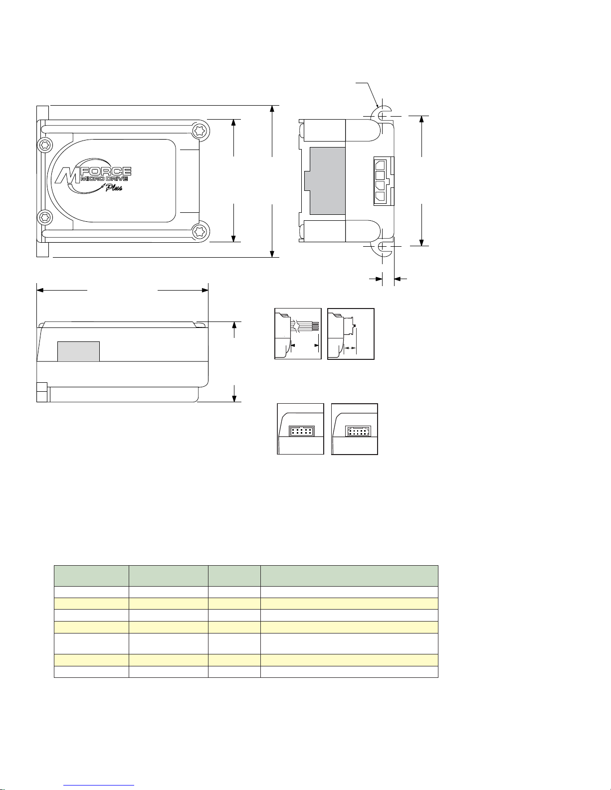
Software Specifications
TM
MOTION CONTROL
P2
P3P1
2.325
(59.06)
1.300
(33.02)
1.655
(42.05)
2.140
(54.36)
1.765
(44.83)
0.201
(5.11)
2X Ø 0.150
(2X Ø 3.81)
0.20
(5.0)
0.14 (3.6)
Program Storage Type/Size Flash/6384 Bytes
User Registers (4) 32 Bit
User Program Labels and Variables 192
Math, Logic and Conditional
Functions
Branch Functions Branch and Call (Conditional)
Party Mode Addresses 62
Encoder Functions Stall Detect, Position Maintenance, Find Index
Predefined I/O Functions
Input Functions
Output Functions Moving, Fault, Stall, Velocity Changing
Trip Functions Trip on Input, Trip on Position, Trip on Time, Trip Capture
Mechanical Specifications
Dimensions in Inches (mm)
+, -, x, ÷, <, >, =, ≤, ≥, AND, OR, XOR, NOT
Home, Limit+, Limit -, Go, Stop, Pause, Jog+, Jog-, Analog
Input
Part 1: Hardware Specifications
Figure 1.3.1: Mechanical Specifications
1-19
Page 28

Pin Assignments and Description
P1 Connector - Power and Expanded I/O Configuration
P1 - Expanded I/O Configuration
16-Pin Wire Crimp Function Description
Pin 1 I/O PWR
Pin 2 I/O GND Non-isolated I/O Ground. Common with Power Ground.
Pin 3 I/O 1 0 to +24 VDC Programmable I/O Point 1
Pin 4 I/O 2 0 to +24 VDC Programmable I/O Point 2
Pin 5 I/O 3 0 to +24 VDC Programmable I/O Point 3
Pin 6 I/O 4 0 to +24 VDC Programmable I/O Point 4
Pin 7 I/O 9 0 to +24 VDC Programmable I/O Point 9
Pin 8 I/O 10 0 to +24 VDC Programmable I/O Point 10
Pin 9 I/O 11 0 to +24 VDC Programmable I/O Point 11
Pin 10 I/O 12 0 to +24 VDC Programmable I/O Point 12
Pin 11 Capture/Trip I/O
Pin 12 AIN 0 to 10 V / 4 to 20 mA / 0 to 20 mA Analog Input.
Pin 13 SCLK
Pin 14 DIR
Pin 15 +V +12 to +48 VDC Motor Power Supply Input.
Pin 16 GND Power and Auxiliary Ground
Recommended
Cable
PD16-1417-FL3
Table 1.3.1: P1 — Pin Assignment, Expanded I/O Configuration
P1 Connector - Power and I/O with Remote Encoder Configuration
I/O Power, used with sourcing inputs or outputs. See
Section 2.3 for more details.
High Speed Capture Input or Trip Output. +5 VDC Logic
Level.
Step Clock I/O. Can also be configured as Quadrature or
Clock Up/Down.
Direction I/O. Can also be configured as Quadrature or
Clock Up/Down.
P1 - Expanded I/O Configuration
16-Pin Wire Crimp Function Description
Pin 1 I/O PWR
Pin 2 I/O GND Non-isolated I/O Ground. Common with Power Ground.
Pin 3 I/O 1 0 to +24 VDC Programmable I/O Point 1
Pin 4 I/O 2 0 to +24 VDC Programmable I/O Point 2
Pin 5 I/O 3 0 to +24 VDC Programmable I/O Point 3
Pin 6 I/O 4 0 to +24 VDC Programmable I/O Point 4
Pin 7 Channel A + Encoder Channel Channel A + Input.
Pin 8 Channel A – Encoder Channel Channel A – Input.
Pin 9 Channel B + Encoder Channel Channel B + Input.
Pin 10 Channel B – Encoder Channel Channel B – Input.
Pin 11 Capture/Trip I/O
Pin 12 AIN 0 to 10 V / 4 to 20 mA / 0 to 20 mA Analog Input.
Pin 13 Index + Encoder Index + Input.
Pin 14 Index – Encoder Index – Input.
Pin 15 +V +12 to +48 VDC Motor Power Supply Input.
Pin 16 GND Power and Auxiliary Ground
Recommended
Cable
PD16-1417-FL3
I/O Power, used with sourcing inputs or outputs. See
Section 2.3 for more details.
High Speed Capture Input or Trip Output. +5 VDC Logic
Level.
Table 1.3.2: P1 — Pin Assignment, Remote Encoder Configuration
1-20
Motion Control MForce MicroDrive Hardware Manual Revision R112706
Page 29

1 3 5 7 9 11 13 15
2 4 6 8 10 12 14 16
P1
P1 Connector
Figure 1.3.2: 16-Pin Wire Crimp Connector P1 Pin Numbers
P2 Connector - RS-422/485 Communications
Pin Assignment - P2 RS-422/485 Communications
10-Pin IDC 10-Pin Wire Crimp Function Description
Pin 1 Pin 9 TX +
Pin 2 Pin 10 TX –
Pin 3 Pin 7 RX +
Pin 4 Pin 8 RX –
Pin 5 Pin 5 Aux-Logic
Pin 6 Pin 6 RX +
Pin 7 Pin 3 RX –
Pin 8 Pin 4 TX –
Pin 9 Pin 1 TX +
Pin 10 Pin 2
Recommended
Converter/Cable
MD-CC400-000
Recommended
Converter/Cable
MD-CC400-000 and
MD-ADP-H
COMM
GND
* For multi-drop communications systems IMS offers the
PD10-1434-FL3 Prototype Development Cable. See Cables
and Cordsets in the Appendices for more details.
Transmit +: Connects to Receive + of the
Communications Host.
Transmit –: Connects to Receive – of the
Communications Host.
Receive +: Connects to Transmit + of the
Communications Host.
Receive –: Connects to Transmit – of the
Communications Host.
+12 to +24 VDC Auxiliary Logic Supply Input.
This provides power to control and logic circuits
if main power is removed.
Receive +: This point will typically be used
to connect to RX+ (Pin 3/7*) of a second
MDrivePlus for Multidrop Communications.
Receive –: This point will typically be used
to connect to RX – (Pin 4/8*) of a second
MDrivePlus for Multidrop Communications.
Transmit –: This point will typically be used
to connect to TX – (Pin 1/9*) of a second
MDrivePlus for Multidrop Communications.
Transmit –: This point will typically be used
to connect to TX + (Pin 2/10*) of a second
MDrivePlus for Multidrop Communications.
Communications Ground. This Ground is ONLY
to be used to ground communications. Auxiliary
Logic Supply must be grounded at the motor
supply ground.
Table 1.3.3: P2 — Pin Assignment, RS-422/485 Communications
Part 1: Hardware Specifications
1-21
Page 30

Recommended Cable:
P/N MD-CC400-000
Recommended Cables:
P/N MD-CC400-000
P/N MD-ADP-H
10-Pin IDC 10-Pin Friction Lock
Wire Crimp
P2
9 7 5 3 1
10 8 6 4 2
P2
1 3 5 7 9
2 4 6 8 10
P3
4-Pin Locking Wire Crimp
1 2 3 4
P2 Connector Options
Figure 1.3.3: P2 Pin Assignment
P3 Connector - Motor Phase Connector
Pin Assignment - P3 Motor
4-Pin Wire Crimp Function Description
Pin 1 ØA Phase A of the Motor
Pin 2 ØA Phase A of the Motor
Pin 3 ØB Phase B of the Motor
Pin 4 ØB Phase B of the Motor
Table 1.3.4: P3 — Pin Assignment, Motor Phase Connections
Recommended Cable: P/N PD04-MF17-FL3
Recommended Connector Shell and Pins
Shell: AMP 1445022-4
Pins: AMP 1-794610-2
Wire: 20 AWG Shielded Twisted Pair
Options and Accessories
Motors and Encoders
IMS offers a wide range of motors, encoders and accessories recommended for interface with the Motion Control
MForce MicroDrive. For complete specifications on these products, please visit the IMS web site at www.imshome.com. See Appendix C for Encoder information and Appendix E for Motor details.
Power Supplies
IMS recommends the following power supplies for operating the MForce MicroDrive: ISP402, ISP404,
ISP200-4. For complete power supply specifications, visit the IMS web site at www.imshome.com. See Ap-
pendix A for recommended IMS power supplies.
P3 Connector
Figure 1.3.4: P3: 4-Pin Locking Wire Crimp Motor
Connector
Communications Converter Cables
These convenient accessory cables connect a PC’s USB Port to the P2 Connector of the MForce MicroDrive.
Total cable length is 12.0' (3.6m). An in-line RS-422 converter enables parameter setting to a single Motion
Control MForce. Purchase recommended with first orders. See Appendix D for details.
USB to 10-Pin IDC ..............................................................................................MD-CC400-000
10-Pin IDC to Wire Crimp Adapter ...........................................................................MD-ADP-H
Prototy pe Development Cables
To speed prototyping, these 10' (3m) cables are available:
I/O: 16-pin Wire Crimp Cable ............................................................................. PD16-1417-FL3
Comm: 10-pin Wire Crimp Cable ........................................................................PD10-1434-FL3
Motor Interface: 4-pin Wire Crimp Cable
1-22
See Appendix D for details.
................................................................. PD04-MF17-FL3
Motion Control MForce MicroDrive Hardware Manual Revision R112706
Page 31

Part 2:
TM
FORCE
MICRO DRIVE
MOTION CONTROL
Connecting and
Interfacing
Excellence in Motion
TM
Section 2.1: Mounting and Connection Recommendations
Section 2.2: Motor Sizing and Selection
Section 2.3: Interfacing Communications
Section 2.4: Interfacing and Using the MForce I/O
Page 32

is Page Intentionally Left Blank
2-2
Motion Control MForce MicroDrive Hardware Manual Revision R112706
Page 33

SE C TI O N 2 .1
TM
MOTION CONTROL
2 x #6-32 Screw
2 x #6 Flat Washer
2 x #6 Split Lockwasher
Mounting Hardware
Maximum Tightening Torque: TBD
1.765
(44.83)
Mounting and Connection Recommendations
Mounting Recommendations
Flange mounting holes are drilled through with a diameter of 0.1.50" (3.81mm) to take standard 6X32 (M3 Metric)
screws. The length of the screw used will be determined by the mounting flange width. See Mechanical Specifications for
mounting hole pattern.
Figure 2.1.1: MForce MicroDrive Mounting Recommendations
DC Power Recommendations
The power requirements for the MForce MicroDrive are:
Output Voltage .....................................................................................................+12 to +48 VDC
Current (max. per unit) ....................................................................................................... 2 Amps
(Actual power supply current requirement will depend upon voltage and load)
Layout and Interface Guidelines
Logic level cables must not run parallel to power cables. Power cables will introduce noise into the logic level cables and
make your system unreliable.
Logic level cables must be shielded to reduce the chance of EMI induced noise. The shield needs to be grounded at the signal
source to earth. The other end of the shield must not be tied to anything, but allowed to float. This allows the shield to act as
a drain.
Power supply leads to the MForce MicroDrive need to be twisted. If more than one driver is to be connected to the same
power supply, run separate power and ground leads from the supply to each driver.
Part 2: Connections and Interface
2-3
Page 34

MForce MicroDrive
Shielded Cable
Control Panel Back
Panel Earth Stud
Sand paint off panel
to ensure bare metal
contact.
Signal
Common
GND
IOx
Switch
Cut drain wire
here. Do not
terminate
Shield Drain
Wire
To Front Panel
of Enclosure
To Earth Ground
Ground Braid
(Short Run)
All other I/O
Drains Connect to
Common Point
Keep Unshielded
Runs Short
Recommended W iring
The following wiring/cabling is recommended for use with the MForce MicroDrive:
Recommended Mating Connectors and Pins
Figure 2.1.2: Grounding and Shielding for Logic Connections
Logic Wiring ......................................................................................................................22 AWG
Wire Strip Length ...................................................................................................0.25” (6.0 mm)
Power and Ground ....................See Appendix B: Recommended Power and Cable Configurations
Communications
10-Pin IDC ................................................................................................ Samtec TCSD-05-01-N
10-pin Friction Lock .................................................................................. Hirose DF11-10DS-2C
Crimp Contact for 10-pin Friction Lock (22 AWG)..................................................... DF11-22SC
Crimp Contact for 10-pin Friction Lock (24 - 28 AWG) .........................................DF11-2428SC
Crimp Contact for 10-pin Friction Lock (30 AWG)..................................................... DF11-30SC
Logic and Power
The following mating connectors are recommended for the MForce MicroDrive Plus2 Units ONLY! Please contact a
JST distributor for ordering and pricing information.
Enhanced I/O - P2
16-pin Locking Wire Crimp Connector Shell ............................................JST PN PADP-16V-1-S
Crimp Pins ..............................................................................................JST PN SPH-001T-P0.5L
Motor
4-Pin Locking Wire Crimp Connector Shell ............................................AMP (Tycho) 1445022-4
Crimp Pins ............................................................................................. AMP (Tycho) 1-794610-2
Recommended Wire .........................................................................20 AWG Shielded Twisted Pair
Securing Power Leads and Logic Leads
Some applications may require that the MForce move with the axis motion. If this is a requirement of your application,
the motor leads must be properly anchored. This will prevent flexing and tugging which can cause damage at critical connection points within the MForce.
2-4
Motion Control MForce MicroDrive Hardware Manual Revision R112706
Page 35
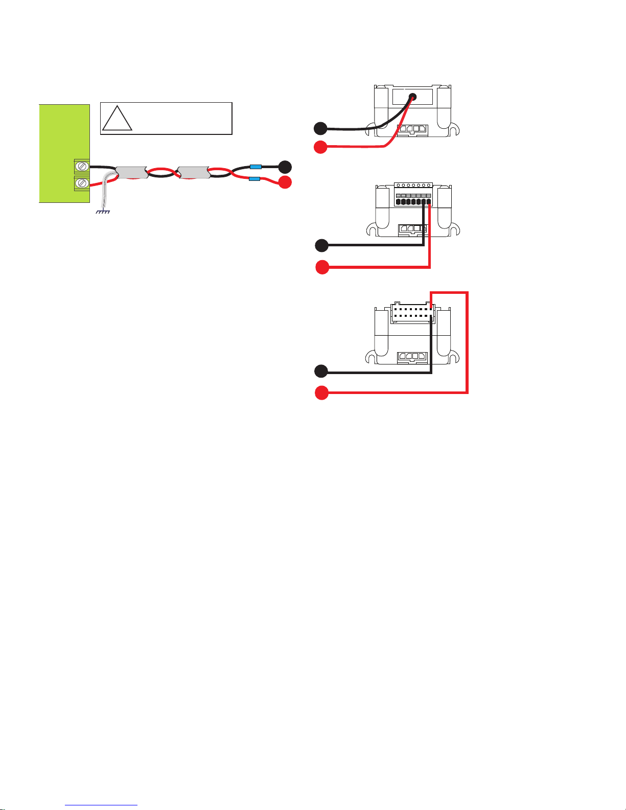
Unregulated
Linear or
Switching
Power Supply
Power
Ground
+VDC
Shield to
Earth Ground
+
–
Shielded Twisted Pair Cable 18AWG
!
WARNING! Do not connect
or disconnect cabling while
power is applied!
Black
Pin 6
Pin 7
Pin 16
Pin 15
Red
1 2 3 4 5 6 7
7-Pin Pluggable Terminal
16-Pin Wire Crimp
12” Flying Leads
A
B
B
B
B
A
A
P1
P1
A
B
B
+V Voltage: +12 to +48* VDC
+V Current: 2A Max Per MForceMicroDrive
Recommended IMS Power Supplies:
ISP200-4
IP402
IP404
*Includes Back EMF!
Power Supply Connection
Figure 2.1.3: MForce MicroDrive Power Connections
Part 2: Connections and Interface
2-5
Page 36

Aux-Logic Supply Connection
!
Black
Pin 6
Pin 5 Pin 5
Pin 16
1 2 3 4 5 6 7
7-Pin Pluggable Terminal
16-Pin Wire Crimp
12” Flying Leads
A
A
A
P1
P1
A
B
B
B
B
Aux-Logic Voltage: +12 to +24 VDC
Aux-Logic Power Requirement:
1.93 Watts (Worst Case)
B
10-Pin IDC
Supply
10-Pin Wire
Crimp
P2 P2
DO NOT Ground the Logic Supply at
Communications Ground or damage will occur
to the drive. Ground Aux Logic at Power Ground.
Side View Front View
+12 to +24 VDC
Ground
The Auxiliary Logic input will maintain power to the Logic circuitry in the absence of motor power. The user will still be
able to communicate with the device, however motion commands will be ignored and the internal counter will update by
the number of pulses commanded. If stall detection is enabled a stall will register.
2-6
Figure 2.1.3: Aux-Logic Connection
Motion Control MForce MicroDrive Hardware Manual Revision R112706
Page 37

SE C TI O N 2 .2
Motor Sizing and Selection
Selecting a Motor
When selecting a stepper motor for your application, there are several factors that need to be taken into consideration:
How will the motor be coupled to the load?
How much torque is required to move the load?
How fast does the load need to move or accelerate?
What degree of accuracy is required when positioning the load?
While determining the answers to these and other questions is beyond the scope of this document, they are details that
you must know in order to select a motor that is appropriate for your application. These details will affect everything
from the power supply voltage to the type and wiring configuration of your stepper motor. The current and microstepping settings of your MForce MicroDrive will also be affected.
Types and Construction of Stepping Motors
The stepping motor, while classed as a DC motor, is actually an AC motor that is operated by trains of pulses. Although
it is called a “stepping motor”, it is in reality a polyphase synchronous motor. This means it has multiple phases wound
in the stator and the rotor is dragged along in synchronism with the rotating magnetic field. The MForce MicroDrive is
designed to work with the following types of stepping motors:
1) Permanent Magnet (PM)
2) Hybrid Stepping Motors
Hybrid stepping motors combine the features of the PM stepping motors with the features of another type of stepping
motor called a variable reluctance motor (VR). VR motors are low torque and load capacity motors which are typically
used in instrumentation. The MForce MicroDrive cannot be used with VR motors as they have no permanent magnet.
On hybrid motors, the phases are wound on toothed segments of the stator assembly. The rotor consists of a permanent
magnet with a toothed outer surface which allows precision motion accurate to within ± 3 percent. Hybrid stepping motors are available with step angles varying from 0.45° to 15° with 1.8° being the most commonly used. Torque capacity
in hybrid steppers ranges from 5 - 8000 ounce-inches. Because of their smaller step angles, hybrid motors have a higher
degree of suitability in applications where precise load positioning and smooth motion is required.
Sizing a Motor for Your System
The MForce MicroDrive is a bipolar driver which works equally well with both bipolar and unipolar motors (i.e. 8 and
4 lead motors, and 6 lead center tapped motors).
To maintain a given set motor current, the MForce MicroDrive chops the voltage using a variable chopping frequency
and a varying duty cycle. Duty cycles that exceed 50% can cause unstable chopping. This characteristic is directly
related to the motor’s winding inductance. In order to avoid this situation, it is necessary to choose a motor with a low
winding inductance. The lower the winding inductance, the higher the step rate possible.
Winding Inductance
Since the MForce MicroDrive is a constant current source, it is not necessary to use a motor that is rated at the same
voltage as the supply voltage. What is important is that the MForce MicroDrive is set to the motor’s rated current.
The higher the voltage used the faster the current can flow through the motor windings. This in turn means a higher
step rate, or motor speed. Care should be taken not to exceed the maximum voltage of the driver. Therefore, in choosing a motor for a system design, the best performance for a specified torque is a motor with the lowest possible winding
inductance used in conjunction with highest possible driver voltage.
The winding inductance will determine the motor type and wiring configuration best suited for your system. While the
equation used to size a motor for your system is quite simple, several factors fall into play at this point.
The winding inductance of a motor is rated in milliHenrys (mH) per Phase. The amount of inductance will depend on
the wiring configuration of the motor.
The per phase winding inductance specified may be different than the per phase inductance seen by your MForce MicroDrive driver depending on the wiring configuration used. Your calculations must allow for the actual inductance that the
driver will see based upon the wiring configuration.
Part 2: Connections and Interface
2-7
Page 38

PHASE A
PHASE A
PHASE B
PHASE B
8 Lead Stepping Motor
Series Configuration
8 Lead Stepping Motor
Parallel Configuration
PHASE A
PHASE A
PHASE B
PHASE B
(Note: This exampl e a lso
applies to the 6 lead motor
full copper conguration and
to 4 lead stepping motors)
(Note: This exampl e a lso
applies to the 6 lead motor
half copper conguration)
Specified Per Phase
Inductance
Specified Per Phase
Inductance
Actual Inductance
Seen By the Driver
Actual Inductance
Seen By the Driver
A B
NOTE: In
calculating
the maximum
phase
inductance, the minimum
supply output voltage
should be used when
using an unregulated
supply.
Figure 2.2.1 A & B: Per Phase Winding Inductance
Figure 2.2.1A shows a stepper motor in a series configuration. In this configuration, the per phase inductance will be 4
times that specified. For example: a stepping motor has a specified per phase inductance of 1.47mH. In this configuration the driver will see 5.88 mH per phase.
Figure 2.2.1B shows an 8 lead motor wired in parallel. Using this configuration the per phase inductance seen by the
driver will be as specified.
Maximum Motor Inductance (mH per Phase) =
.2 X Minimum Supply Voltage
Using the following equation we will show an example of sizing a motor for an MForce MicroDrive used with an unregulated power supply with a minimum voltage (+V) of 18 VDC:
.2 X 18 = 3.6 mH
The recommended per phase winding inductance we can use is 3.6 mH.
Recommended IMS Motors
IMS also carries a series of 14, 17 and 23 frame enhanced stepping motors that are recommended for use with the MForce
MicroDrive. These motors use a unique relationship between the rotor and stator to generate more torque per frame size while
ensuring more precise positioning and increased accuracy.
The special design allows the motors to provide higher torque than standard stepping motors while maintaining a steadier
torque and reducing torque drop-off.
These CE rated motors are ideal for applications where higher torque is required.
For more detailed information on these motors, please see the IMS Full Line catalog or the IMS web site at http://www.
imshome.com.
2-8
Motion Control MForce MicroDrive Hardware Manual Revision R112706
Page 39

14 Frame Enhanced (0.75A)
Single Shaft Double Shaft
M-1410-0.75S ........................................................................................................M-1410-0.75D
17 Frame Enhanced (1.5A)
Single Shaft Double Shaft
M-1713-1.5S ............................................................................................................M-1713-1.5D
M-1715-1.5S ............................................................................................................M-1715-1.5D
M-1719-1.5S ............................................................................................................M-1719-1.5D
23 Frame Enhanced (2.4A) — Not Available with Double Shaft
Single Shaft Double Shaft
M-2218-2.4S ............................................................................................................................N/A
M-2222-2.4S ............................................................................................................................N/A
M-2231-2.4S ............................................................................................................................N/A
IMS Inside Out Stepper Motors
The new inside out stepper (IOS) motor was designed by IMS to bring versatility to stepper motors using a unique multifunctional, hollow core design.
This versatile new motor can be converted to a ball screw linear actuator by mounting a miniature ball screw to the front
shaft face. Ball screw linear actuators offer long life, high efficiency, and can be field retrofitted. There is no need to throw
the motor away due to wear of the nut or screw.
The IOS motors offer the following features:
The shaft face diameter offers a wide choice of threaded hole patterns for coupling.
The IOS motor can be direct coupled in applications within the torque range of the motor,
eliminating couplings and increasing system efciency.
The IOS motor can replace gearboxes in applications where gearboxes are used for inertia
damping between the motor and the load. The induced backlash from the gearbox is eliminated
providing improved bidirectional position accuracy.
Electrical or pneumatic lines can be directed through the center of the motor enabling the motors
to be stacked end-to-end or applied in robotic end effector applications. The through hole is
stationary, preventing cables from being chaffed by a moving hollow shaft.
Light beams can be directed through the motor for refraction by a mirror or lter wheel mounted
on the shaft mounting face.
The IOS motor is adaptable to valves enabling the valve stem to protrude above the motor frame.
The stem can be retrotted with a dial indicator showing valve position.
The motor is compatible with IMS bipolar drivers, keeping the system cost low.
The IOS motor can operate up to 3000 rpm’s.
The IOS motor is available in the following frames:
Frame Size IMS PN
17 Frame ...................................................................................................................M3-1713-IOS
23 Frame ...................................................................................................................M3-2220-IOS
Part 2: Connections and Interface
2-9
Page 40

Motor Wiring
P3
1 2 3 4
PHASE B
PHASE B
PHASE A
PHASE A
Splice
Splice
As with the power supply wiring, motor wiring should be run separately from logic wiring to minimize noise coupled
onto the logic signals. Motor cabling exceeding 1’ in length should be shielded twisted pairs to reduce the transmission of
EMI (Electromagnetic Interference) which can lead to rough motor operation and poor system performance. Below are
listed the recommended motor cables:
Dual Twisted Pair Shielded (Separate Shields)
≤ 5 feet ...................................................................................Belden Part# 9402 or equivalent 20 Gauge
≥ 5 feet ...................................................................................Belden Part# 9368 or equivalent 18 Gauge
When using a bipolar motor, the motor must be within 100 feet of the drive.
Connecting the Motor
The motor leads are connected to the following connector pins:
Phase Connector: Pin
Phase A ...................................................................................................................................P4: 1
Phase A ...................................................................................................................................P4: 2
Phase B ................................................................................................................................... P4: 3
Phase B ................................................................................................................................... P4: 4
8 Lead Motors
8 lead motors offer a high degree of flexibility to the system designer in that they may be connected in series or parallel, thus
satisfying a wide range of applications.
Series Connection
A series motor configuration would typically be used in applications where a higher torque at lower speeds is required. Because this configuration has the most inductance, the performance will start to degrade at higher speeds.
Use the per phase (or unipolar) current rating as the peak output current, or multiply the bipolar current rating by
1.4 to determine the peak output current.
Figure 2.2.2: 8 Lead Motor Series Connections
Parallel Connection
An 8 lead motor in a parallel configuration offers a more stable, but lower torque at lower speeds. But because of the
lower inductance, there will be higher torque at higher speeds. Multiply the per phase (or unipolar) current rating by
1.96, or the bipolar current rating by 1.4, to determine the peak output current.
2-10
Motion Control MForce MicroDrive Hardware Manual Revision R112706
Page 41

Figure 2.2.3: 8 Lead Motor Parallel Connections
P3
1 2 3 4
PHASE B
PHASE B
PHASE A
PHASE A
P3
1 2 3 4
PHASE B
NO CONNECTION
NO CONNECTION
PHASE B
PHASE A
PHASE A
6 Lead Motors
Like 8 lead stepping motors, 6 lead motors have two configurations available for high speed or high torque operation. The higher speed configuration, or half coil, is so described because it uses one half of the motor’s inductor
windings. The higher torque configuration, or full coil, uses the full windings of the phases.
Half Coil Configuration
As previously stated, the half coil configuration uses 50% of the motor phase windings. This gives lower inductance,
hence, lower torque output. Like the parallel connection of 8 lead motor, the torque output will be more stable at
higher speeds. This configuration is also referred to as half copper. In setting the driver output current multiply the
specified per phase (or unipolar) current rating by 1.4 to determine the peak output current.
Full Coil Configuration
Figure 2.2.4: 6 Lead Half Coil (Higher Speed) Motor Connections
The full coil configuration on a six lead motor should be used in applications where higher torque at lower speeds
is desired. This configuration is also referred to as full copper. Use the per phase (or unipolar) current rating as the
peak output current.
Part 2: Connections and Interface
2-11
Page 42
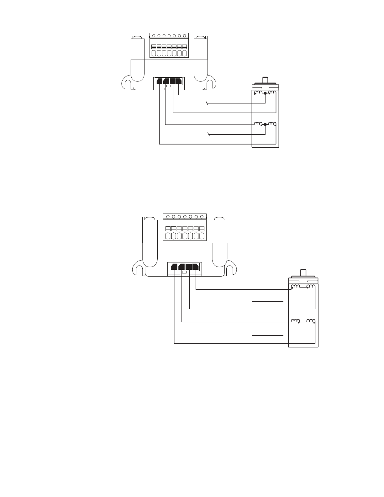
P3
1 2 3 4
PHASE B
PHASE B
PHASE A
PHASE A
3
P3
1 2 3 4
PHASE B
NO CONNECTION
NO CONNECTIO N
PHASE B
PHASE A
PHASE A
Figure 2.2.5: 6 Lead Full Coil (Higher Torque) Motor Connections
4 Lead Motors
4 lead motors are the least flexible but easiest to wire. Speed and torque will depend on winding inductance. In setting the
driver output current, multiply the specified phase current by 1.4 to determine the peak output current.
2-12
Figure 2.2.6: 4 Lead Motor Connections
Motion Control MForce MicroDrive Hardware Manual Revision R112706
Page 43

SE C TI O N 2 .3
MForce MicroDrive
P2
RS-422
Converter
COMM GND
COMM GND
TX+RX+
TX-
RX-
RX+
RX-
TX+
TX-
Host PC
USB/Serial Port
10-Pin IDC at P2 Shown
See Specifications for Pin
Numbering for the
Wire-Crimp version.
COMM GND is ONLY to be used for grounding
communications. Grounding Aux-Logic or
any other device to COMM GND may
damage the MForce!
100Ω Internal on
MForce to Prevent
Comm. Ground Loops
Interfacing Communications
Available Communications Cables/Converters
To simplify the wiring and connection process IMS offers a USB to RS-422 communications cable for the MForce MicroDrive. This convenient 12.0' (3.6m) accessory cable connects a PC’s USB Port to the
tor. An in-line RS-422 converter enables parameter setting to a single
MForce MicroDrive
with first orders.
USB to 10-Pin IDC .................................................Part No. MD-CC400-000
10-Pin IDC to Wire Crimp Adapter ........................Part No. MD-ADP-H
For more information on these cables please reference Appendix D: Optional Cables and Cordsets.
Interfacing Single Mode Communications
The MForce MicroDrive communicates to the host using the RS-422/485 protocol. Communications may be configured
as either half duplex (RS-485) or full duplex (RS-422) using the EM (Echo Mode) Instruction. RS-422/485 may be used
in two ways: either to communicate to a single MForce MicroDrive, or to address up to 62 individually named MForce
MicroDrive nodes in a multidrop system.
MForce MicroDrive
P2 Connec-
. Cable purchase recommended
Note: See the
Specications
Section of
this document
specic to the MForce
MicroDrive model you
purchased for detailed
connector and pin
information.
WARNING!
Do not
connect or
disconnect
the Communications
Converter Cable while
power is applied!
Single
Mode Communications Full Duplex (
RS-422)
To interface the MForce MicroDrive using RS-422 protocol you will need one of the following:
A PC equipped with RS-422 Interface.
A PC RS-232 to RS-422/485 Converter.
The USB to RS-422 accessory cable.
Use the following diagram to connect RS-422 communications to the MForce MicroDrive.
Figure 2.3.1: Full Duplex Communications (RS-422)
WARNING!
If using AUX-
Logic, the
Power return
MUST be connected
to the Motor Power
Ground. DO NOT
connect the return
to Communications
Ground!
Part 2: Connections and Interface
2-13
Page 44

Single Mode Communications Half Duplex (RS-485)
MFORCE PLUS MOTION CONTROL
100Ω
HOST PC INTERFACE
2 Wire RS-485
Comm GND
B
A
RXRX+
TXTX+
10-PIN IDC
10-PIN
FRICTION LOCK
WIRE CRIMP
MDrive34Plus/Plus
2
CGND
Pin 4,10
Pin 1, 9
Pin 6, 7
Pin 3, 8
Pin 2
Pin 2, 8
Pin 1, 9
Pin 3, 6
Pin 4, 7
Pin 10
The MForce MicroDrive can be operated in a 2 wire RS-485 communication bus. Before connecting the 2 wire RS-485,
download your program and setup instructions using the standard 4 wire RS-422 Communications Cable. If a program
is not being used, download and save any setup parameters. To ensure the MForce MicroDrive responds only to commands specifically meant for it, set the unit in Party Mode (Please see Party Mode below). The Echo Mode command
(EM) must be set to the value of 1 (EM=1). This will set the MForce MicroDrive communication into “half duplex”
mode. Connect the driver in the 2 wire RS-485 configuration. The following diagram illustrates how to connect the
MForce MicroDrive 4 wire RS-485 to operate as a 2 wire system.
Figure 2.3.2: Half Duplex 2 Wire Communications (RS-485)
Interfacing Party Mode Communications
In systems with multiple controllers it is necessary to communicate with the control modules using party mode
(PY=1). The MForce MicroDrive nodes in the system are configured in software for this mode of operation by
setting the Party Flag (PY) to True (1). It is necessary for all of the nodes in a system to have this configuration
selected. When operating in party mode, each MForce in the system will need a unique address, or name, to identify
it in the system. This is accomplished by using the software command DN, or Device Name. For example, to
set the name of an MForce to “A” you would use the following command: DN=65 or DN=”A” (65 is the ASCII
decimal equivalent of uppercase A). The factory default name is “!”. The asterisk character “*” is used to issue global
commands to every device in the system. NOTE: When using the asterisk “*” in Party Mode, typed entries and
commands will not be echoed. See Appendix A of the Software Reference for ASCII table.
In setting up your system for party operation, the most practical approach is to observe the following steps:
1. Connect the first MForce MicroDrive to the Host PC configured for Single Mode Operation.
2. Establish communications and download program if required.
3.
Using the command DN, name the MForce MicroDrive. This can be any upper or lower case ASCII character or
number 0-9. (DN=”A”{enter}) (Note: The quotation marks before and after the device name are required.)
4. Set the party flag PY=1{enter}.
5. Press CTRL+J to activate the Party Mode.
6. Type the letters AS and press CTRL+J (Save device name and Party Mode).
7. Remove power.
8. Repeat steps 1 through 7 for each additional MForce in the system.
9. After all MForce MicroDrives are assigned a Device Name, the Multiple MForce Interface can be configured as
shown in the following figure.
Data Cable Termination Resist ors
Data Cable lengths greater than 15 feet (4.5 meters) are susceptible to signal reflection and/or noise. IMS recommends
120 Ω termination resistors in series with 0.1µf capacitors at both ends of the Data Cables. An example of resistor placement is shown in Figure 2.3.3. For systems with Data Cables 15 feet (4.5 meters) or less, the termination resistors are
generally not required.
2-14
Motion Control MForce MicroDrive Hardware Manual Revision R112706
Page 45
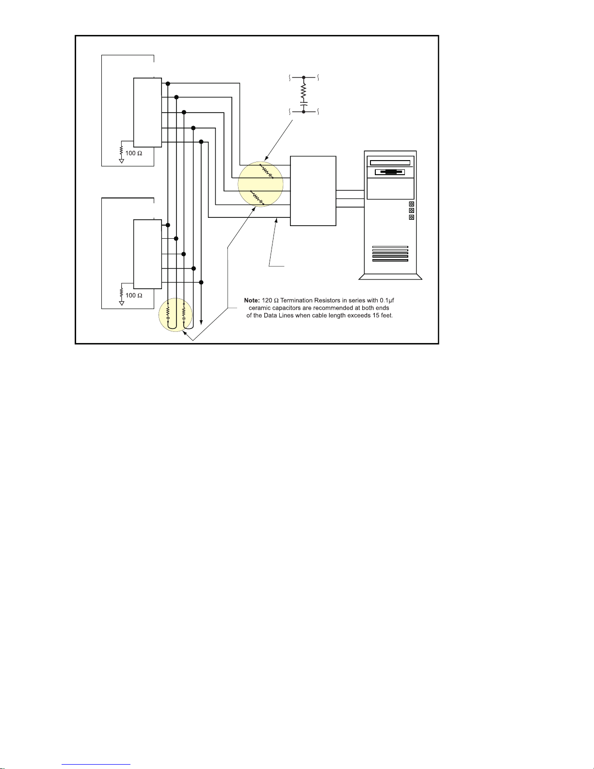
MForce Plus Motion Control #1
(DN=A)
Mating
Connector*
RX
-
RX
+
TX
-
TX
+
CGND
MForce Plus Motion Control #2
(DN=B)
Mating
Connector*
RX
-
RX
+
TX
-
TX
+
CGND
* Mating Connector
Samtec
P/N
TCSD-05-01-N
Ribbon Cable
AMP
10WDY00005
P
RS-232 to RS-422
Converter
TX
RX
CGND
HOS
T
TX+
TX-
RXRX+
CGND
R
TERMINATOR
C
TERMINATOR
MFor ce MicroDrive Communication Format
The following communication formats are used by the MForce MicroDrive.
{} The contents between the {} symbols are transmitted.
{0D} Hex equivalent for a CR (Carriage Return).
{0A} Hex equivalent for a LF (Line Feed).
{DN} Represents the Device Name being sent.
{CS} Check Sum; {ACK} 06 Hex; {NAK} 15 Hex
EM = Echo Mode; PY = PartY Mode; CK= ChecK sum
The word {command} represents the immediate command sent to the MForce MicroDrive.
Command Execution Time (CET) is the time the MForce MicroDrive takes to execute a command. This varies from
command to command and usually is in the 1-5 millisecond range.
MFor ce MicroDrive Response to Echo Mode
Dependent on how the Echo Mode (EM) is set in conjunction with Party Mode (PY) and Check Sum (CK), the MForce
MicroDrive will respond differently. The following tables illustrate the various responses based on how the EM, PY and
CK parameters are set.
Figure 2.3.3: RS-485 Interface, Multiple MForce MicroDrive System
Part 2: Connections and Interface
2-15
Page 46

Transmission
Parameter Setting
EM=0 & PY=0 CK=0 (command) (D)
EM=1 & PY=0 CK=0 (command) (0D) − CET (0D) (0A)
EM=2 & PY=0 CK=0 (command) (0D) − −
EM=3 & PY=0 CK=0 (command) (0D) −
to MForce
MicroDrive
MForce MicroDrive
Initial Response
(command)
Echoed back one
character at a time
as the character is
entered.
MForce
MicroDrive Final
Response
CET (0D) (0A)>
CET command
(0D) (0A)
Table 2.3.1: MForce MicroDrive Response to Echo Mode - Party and Check Sum are Zero (0)
Notes
The last character
sent is the prompt >
The last character
sent is LF
No response
except to PR and L
commands
Queued response.
The last character
sent is the LF
Parameter Setting
EM=0 & PY=1 CK=0 (DN) (command) (0A)
EM=1 & PY=1 CK=0 (DN) (command) (0A) − CET (0D) (0A)
EM=2 & PY=1 CK=0 (DN) (command) (0A) − −
EM=3 & PY=1 CK=0 (DN) (command) (0A) −
Transmission to
MForce MicroDrive
MForce MicroDrive
Initial Response
(command)
Echoed back one
character at a time
as the character is
entered.
MForce
MicroDrive
Final
CET (0D)
(0A)>
CET
command
(0D) (0A)
Table 2.3.2: MForce MicroDrive Response to Echo Mode - Party is One (1) and Check Sum is Zero (0)
Parameter Setting
EM=0 & PY=0 CK=1 (DN) (command) (0A)
EM=1 & PY=0 CK=1 (DN) (command) (0A) − CET (0D) (0A)
EM=2 & PY=0 CK=1 (DN) (command) (0A) − −
EM=3 & PY=0 CK=1 (DN) (command) (0A) −
Transmission to
MForce MicroDrive
MForce
MicroDrive Initial
Response
(command)
Echoed back one
character at a time
as the character is
entered.
MForce
MicroDrive Final
Response
CET (0D) (0A)>
CET command
(0D) (0A)
Notes
The last
character sent
is the prompt >
The last
character sent
is LF
No response
except to
PR and L
commands
Queued
response. The
last character
sent is the LF
Notes
The last
character sent
is the prompt
>
The last
character sent
is LF
No response
except to
PR and L
commands
Queued
response. The
last character
sent is the LF
Table 2.3.3: MForce MicroDrive Response to Echo Mode - Party is Zero (0) and Check Sum is One (1)
2-16
Motion Control MForce MicroDrive Hardware Manual Revision R112706
Page 47

Parameter Setting
EM=0 & PY=1 CK=1
EM=1 & PY=1 CK=1
EM=2 & PY=1 CK=1
EM=3 & PY=1 CK=1
Transmission
to MForce
MicroDrive
(DN) (command)
(CS) (0A)
(DN) (command)
(CS) (0A)
(DN) (command)
(CS) (0A)
(DN) (command)
(CS) (0A)
MForce
MicroDrive Initial
Response
(command)
Echoed back one
character at a time
as the character is
entered.
−
− −
−
MForce MicroDrive
Final Response
CET (ACK) or
(NAK)>
CET (ACK) or
(NAK)>
CET command
(CS) (ACK) (NAK)
Notes
The last character
sent is the prompt >
The last character
sent is ACK or NAK
No response
except to PR and L
commands
Queued response.
The last character
sent is ACK or NAK
Table 2.3.4: MForce MicroDrive Response to Echo Mode - Party and Check Sum are One (1)
Using Check Sum
For communication using Check Sum, the following 2 commands demonstrate sending and receiving.
Sending Command
1. Check Sum set to ZERO before first character is sent.
2. All characters (ASCII values) are added to Check Sum, including the Device Name DN (if PY=1), to the end of
the command, but not including terminator.
3. Check Sum is 2’s complement, then “OR” ed with Hex 80 (prevents Check Sum from being seen as Command
Terminator).
4. Terminator Sent.
Example command:
MR (space) 1 Note: Any combination of upper/lower case may be used. In this example,
if a lower case <mr> were to be used, the decimal values will change to
109 and 114. Subsequently the Result Check Su m va l ue w ill cha n ge.
(Po ss i b le e nt r i es: MR, mr, Mr, m R .) ( M = 77, R = 8 2, m =
109, r = 114) (See ASCII table appendix in MForce MicroDrive Software
Manual.)
77 82 32 49 Decimal value of M, R, <space> and 1
4D 52 20 31 Hex
77+82+32+49 = 240 Add decimal values together
1111 0000 = 240 Change 240 decimal to binary
0000 1111 1’s complement (invert binary)
0001 0000 Add 1 [2’s complement]
1000 0000 OR result with 128 (Hex 80)
1001 0000 144 Result Check Sum value
Once the result is reached, add the check Sum value (144 in this example) to your string by typing: MR 1(Alt Key +
0144) (Use the symbol of 0144 in your string by holding down the alt key and typing 0144). You must type the numbers
from the Numlock key pad to the right of the keyboard. The numbers at the top of the keyboard will not work.
Receiving Command
1. Check Sum set to ZERO.
2. All characters are added to Check Sum.
3. When receiving a Command Terminator, the lower 7 bits of the Check Sum should be equal to ZERO.
a) If not ZERO, the command is ignored and NAK echoed.
b) If ZERO, ACK is sent instead of CR/LF pair.
4. Responses to PR commands will be Check Summed as above, but the receiving device should NOT respond
with ACK or NAK.
Part 2: Connections and Interface
2-17
Page 48

MFor ce MicroDrive Party Mode Sample Codes
1. Download this segment of code into the first MForce MicroDrive. After downloading the program to the
unit, follow the Set Up instructions described earlier. Be sure to set your first unit with the unique Device
Name of A (DN=”A”). The device name is case sensitive.
RC=25 ‘Run current
HC=5 ‘Hold current
MS=256 ‘Microstep selection
A=250000 ‘Acceleration
D=250000 ‘Deceleration
PG 1 ‘Enter program mode
S1=0,0 ‘Setup I/O 1 as an input low true
LB SU ‘Start program upon power up
LB AA ‘Label program AA
MR 104400 ‘Move relative 104400 counts
H ‘Hold program execution to complete the move
LB DD ‘Label program DD
BR DD,I1=0 ‘Branch to DD if I1=0
4PR “Bex 1” ‘Print device name B to execute program
‘at address 1
H 2000 ‘Hold program execution 2000 milliseconds
PR “Cex 1” ‘Print device name C to execute program at
‘address 1
H 2000 ‘Hold program execution 2000 milliseconds
BR AA ‘Branch to label AA
E
PG ‘Exit program, return to immediate mode
2. Download this segment of code into your second MForce MicroDrive. After downloading the program to
the unit, follow the previous party mode instructions. Be sure to set your second unit with the unique address
of B (device name is case sensitive).
RC=25 ‘Run current
HC=5 ‘Hold current
MS=256 ‘Microstep selection
A=250000 ‘Acceleration
D=250000 ‘Deceleration
PG 1 ‘Enter program mode
LB BB ‘Label program BB
MR 208000 ‘Move relative 208000 counts
H ‘Hold program execution to complete the move
E
PG ‘Exit program, return to immediate mode
3. Download this segment of code into your third MForce MicroDrive. After downloading the program to the
unit, follow the previous party mode instructions. Be sure to set your third unit with the unique address of C
(device name is case sensitive).
RC=25 ‘Run current
HC=5 ‘Hold current
MS=256 ‘Microstep selection
A=250000 ‘Acceleration
D=250000 ‘Deceleration
PG 1 ‘Enter program mode
LB CC ‘Label program CC
MR 300000 ‘Move relative 300000 counts
H ‘Hold program execution to complete the move
E
PG ‘Exit program, return to immediate mode
2-18
Motion Control MForce MicroDrive Hardware Manual Revision R112706
Page 49

MFor ce MicroDrive Immediate Party Mode Sample Codes
Once Party Mode has been defined and set up as previously described under the heading “Multiple MForce MicroDrive
System (Party Mode)”, you may enter commands in the Immediate Mode in the IMS Terminal Window. Some examples
follow.
Move MForce A, B or C 10000 Steps
Assuming there are three MForce MicroDrives set up in Party Mode as shown in the Sample Codes above.
To move MForce Unit “A”, Press Ctrl+J and then type: AMR
10000 and press Ctrl+J. MForce Unit “A” will
^
move 10000 steps.
To print the position type: APR P and press Ctrl+J. The position of MForce Unit “A” will be printed.
To move MForce Unit “B” type: BMR 10000 and press Ctrl+J. MForce Unit “B” will move 10000 steps.
To move all three MForce MicroDrives at the same time type: *MR 10000 and press Ctrl+J. All MForce
MicroDrives will move 10000 steps.
To change a Variable in the “C” unit type: C<variable name><number> and press Ctrl+J. The variable will be
changed. To verify the change type: CPR <variable name> and press Ctrl+J. The new value will be displayed.
All Commands and Variables may be programmed in this manner.
To take an MForce out of Party Mode type: <device name>PY=0 and press Ctrl+J. That unit will be taken out
of Party Mode. To take all units out of Party Mode type: *PY=0 and press Ctrl+J. All units will be taken out of
Party Mode.
NOTE: When
instructed to
type Ctrl+J, that
is the key + the
key. It will not display
in the Terminal Window
so be certain you press
the correct keys. CtrlJ
activates the Party Mode.
NOTE: Once
you have
activated Party Mode
with the rst Ctrl+J you
do not have to type it
before each successive
command. However,
every command must be
followed with a Ctrl+J.
NOTE: The
asterisk (*) is a
global command which
addresses all units.
Since three units can
not answer together, the
asterisk (*) as well as
other global commands
will not be displayed in
the Terminal Window.
Part 2: Connections and Interface
2-19
Page 50

NOTE: On
INPUTS
• Sensors
• Switches
• PLC Outputs
• Outputs of
Additional
System MDrive's
OUTPUTS
• Relays
• Solenoids
• LED's
• PLC Inputs
• Inputs of
Additional
System MDrive's
P1
P3
the Standard
MForce
MicroDrive, when
congured as outputs,
the I/O set is sinking
ONLY! The Plus2 Models
add the functionality of I/
O Power, which enables
the user to use all the
outputs, both Standard
and Enhanced, as
Sinking or Sourcing.
NOTE: If the
unit purchased
has the remote encoder
option, the additional
points become dedicated
to encoder functions!
SE C TI O N 2 .4
Interfacing and Using the MForce MicroDrive I/O
The MForce MicroDrive Digital I/O
The MForce MicroDrive product line is available with two digital I/O configurations, Standard and Enhanced.
The digital I/O may be defined as either active HIGH or active LOW. When the I/O is configured as active HIGH,
the level is +5 to +24 VDC and the state will be read/set as a “1”. If the level is 0 VDC, then the state will be read/set
as “0”. Inversely, if configured as active LOW, then the state of the I/O will be read/set as a “1” when the level is LOW,
and “0” when the level is HIGH. The active HIGH/LOW state is configured by the third parameter of the I/O Setup
(S1-4, S9-12) variable. The goal of this I/O configuration scheme is to maximize compatibility between the MForce
MicroDrive and standard sensors and switches.
Standard ................................................................................ All MForce MicroDrive
Available Points .................................................................IO1, IO2, IO3, IO4 (Sinking or
Sourcing Inputs, Sinking
Outputs ONLY)
Enhanced (16-Pin) ................................................................. Plus2 Only
Available Points .................................................................IO1, IO2, IO3, IO4 (Sinking
Sourcing, Outputs/Inputs)
Additional Points ............................................................... IO9, IO10, IO11, IO12 (Sinking
Sourcing, Outputs/Inputs)
Dedicated I/O ...................................................................Step/Clock Input, Step/Direction
I/O, Capture Input/Trip Output
Remote Encoder Configuration (16-Pin) ................................ Plus2 Only
Standar d I/O Set
The MForce MicroDrive comes standard with a set of four I/O — (4) sinking or sourcing 0 to +24 VDC inputs or (4)
sinking 0 to +24 VDC outputs, which may be programmed individually as either general purpose or dedicated inputs or
outputs, or collectively as a group.
Enhanced I/O Set - MForce MicroDrive Plus2 Version
The MForce MicroDrive Plus2 Version is equipped with a set of eight I/O — (8) sinking or sourcing 0 to +24 VDC
inputs or (8) sinking or sourcing +12 to +24 VDC outputs, which may be programmed individually as either general
purpose or dedicated inputs or outputs, or collectively as a group. The eight I/O consist of two separate banks of four
points: Bank 1: IO1 - IO4, Bank 2: IO9 - IO12.
Uses of the Digital I/O
The I/O may be utilized to receive input from external
devices such as sensors, switches or PLC outputs. When
configured as outputs, devices such as relays, solenoids,
LEDs and PLC inputs may be controlled from the MForce
MicroDrive.
2-20
Each I/O point may be individually programmed to any one
of 9 dedicated input functions, 4 dedicated output functions, or as general purpose inputs or outputs. The I/O may
be addressed individually, or as a group. The active state of
the line or group may also be set. All of these possible functions are accomplished with the I/O Setup Variable (S1-4,
S9-12)
When the level is HIGH. The active HIGH/LOW state is
Available Points .................................................................IO1, IO2, IO3, IO4 (Sinking
Sourcing, Outputs/Inputs)
Dedicated I/O ...................................................................Capture Input/Trip Output
Remote Encoder I/O ......................................................... Channel A±, Channel B±, Index±
Figure 2.4.1: Uses for the Digital I/O
Motion Control MForce MicroDrive Hardware Manual Revision R112706
Page 51

configured by the second parameter of the I/O Setup (S1-4, S9-12) variable. The goal of this I/O configuration scheme is to
maximize compatibility between the MForce MicroDrive and standard sensors and switches.
MForce MicroDrive Digital Input Functions
The MForce MicroDrive inputs may be interfaced to a variety of sinking or sourcing devices. An input may be programmed to
be a general purpose user input, or to one of nine dedicated input functions. These may then be programmed to have an active
state of either HIGH or LOW.
The inputs are configured using the “S” Variable (See MCode Software Reference Manual for precise details on this command).
The command is entered into the IMS terminal or program file as S<IO point>=<IO Type>,<Active State><Sink/Source>.
Example:
S9=3,1,0 ‘set IO point 9 to be a Limit- input, Active HIGH, Sourcing
S3=0,0,1 ‘set IO Point 3 to be a General Purpose input, Active LOW,
‘Sinking
Input Functions (I/O Points 1-4, 9-12)
The following table lists the programmable input functions of the MForce.
Function Description
General Purpose Input function
used to control program branches,
General Purpose
Home
Limit +
Limit –
G0
Soft Stop
Pause
Jog +
Jog –
Reset
subroutine calls or BCD functions
when input bank is used as a
group
Homing input. Will function as
specified by the Home (HM)
command.
Positive Limit Input. Will function
as specified by the Limit (LM)
Command.
Negative Limit Input. Will function
as specified by the Limit (LM)
Command.
G0 Input. Will run program located
at address 1 on activation.
Soft Stop input. Stops motion with
deceleration and stops program
execution.
Pause/Resume program with
motion.
Will Jog motor in the positive
direction at Max. Velocity (VM).
The Jog Enable (JE) Flag must be
set for this to function.
Will Jog motor in the negative
direction at Max. Velocity (VM).
The Jog Enable (JE) Flag must be
set for this to function.
When set as RESET input, then
the action is equivalent to a ^C
entered into a terminal.
Table 2.4.1: Programmable Input Functions
Parameter
(S1-S4, S9-S12)
0 0/1 0/1
1 0/1 0/1
2 0/1 0/1
3 0/1 0/1
4 0/1 0/1
5 0/1 0/1
6 0/1 0/1
7 0/1 0/1
8 0/1 0/1
11 0/1 0/1
Active
Sink/
Source
Part 2: Connections and Interface
2-21
Page 52

NOTE: On the Standard
MForce
MicroDrive,
when
congured
as outputs, the I/O
set is sinking ONLY!
The Plus2 Models add
the functionality of I/O
Power, which enables
the user to use all the
outputs, both Standard
and Enhanced, as
Sinking or Sourcing.
Input Functions (Points 7 & 8 — Clock Inputs and Point 13 — Capture)
Function Description
Sets I/O 7 and 8 to receive step and
direction inputs from an external source.
The motion will occur based on the input
Step/Direction
Quadrature
Up/Down
Function Description
High Speed
Capture
frequency seen at I/O 7 in the Direction
relative to the logic state of I/O 8. The
step rate will be based upon the ratio set
by Clock Ratio (CR)
Sets I/O 7 and 8 to receive Channel A
and Channel B Quadrature inputs from
an external source such as an encoder.
The motion will follow the Quadrature
Input.
Sets I/O 7 and 8 to receive Clock
Up/Clock Down inputs from an external
source. The motion will occur based
upon the input clock frequency in the
direction relative to the input being
clocked. The step rate will be based
upon the ratio set by Clock Ratio (CR)
The Capture input is a momentary
high speed input that operates with
the Trip Capture (TC) variable to run
a subroutine upon the trip. It feature
variable input filtering ranging from 50
nS to 12.9 µS
Parameter
(S7, S8)
33 0/1
34 0/1
35 0/1
Parameter
(S13)
60 0/1
Table 2.4.2: Dedicated Input Functions
Active
Active
Active States Defined
The Active State determines at what voltage level the input will be active.
Active HIGH ........................................ The input will be active when +5 to +24 VDC is applied to the input.
Active LOW ..........................................The input will be active when it is grounded (0 VDC).
Active LOW example:
IO 1 is to be configured as a Jog– input which will activate when a switch is toggled to ground (Sinking Input):
S1=8,0,0 ‘set IO point 1 to Jog–, Active LOW, Sinking
Active HIGH example:
IO 4 is to be configured as a Home input which will activate when instructed by a PLC (+24VDC Sourcing
Input):
S4=1,1,1 ‘set IO point 1 to Home, Active HIGH, Sourcing
MForce MicroDrive Digital Output Functions
The MForce MicroDrive Outputs may be configured as general purpose or set to one of two dedicated functions,
Fault or Moving. These outputs will sink up to 600 mA (one channel of two banks) and may be connected to an
external VDC source. See Output Functions Table and I/O Ratings Table.
The outputs are set using the “S” command (See MCode Software Reference Manual for precise details on this
command). The command is entered into the IMS terminal or program file as S<IO point>=<IO Type>,<Active
State><Sink/Source>.
Example:
S9=17,1,0 ‘set IO point 9 to be a Moving Output, Active HIGH, Sinking
S3=18,0,0 ‘set IO Point 3 to be a Fault Output, Active LOW, Sinking
2-22
Motion Control MForce MicroDrive Hardware Manual Revision R112706
Page 53

Program mable Output Functions
The MForce MicroDrive Output functions may be programmed to be a general purpose user output or to one of five
output functions.
Function Description
A general purpose output can be
General Purpose
User
Moving
Fault
Stall
Velocity Changing
set in a program or in immediate
mode to trigger external events.
When used as a group they can
be a BCD output.
Will be in the Active State when
the motor is moving.
Will be in the Active State when a
error occurs. See Software Manual
for error code listing.
Will be in the Active State when
a stall is detected. Encoder
Required, Stall Detect Mode (SM)
must be enabled.
Will be in the Active State
when the velocity is changing.
Example: during acceleration and
deceleration.
Parameter
(S1-S4, S9-S12)
16 0/1 0/1
17 0/1 0/1
18 0/1 0/1
19 0/1 0/1
20 0/1 0/1
Active
Sink/
Source
Table 2.4.3: Programmable Output Functions
Output Functions (Points 7 & 8 — Clock Outputs and Point 13 — Trip)
Function Description
Step clock pulses will be output from
Point 7, Direction from Point 8. The step
clock output rate will be based upon the
Step/Direction
Quadrature Will output Quadrature signals. 50 0/1
Up/Down
Function Description
High Speed Trip
Pulse Width set by Clock Width (CW).
The logic state of the Direction output
will be with respect to the direction of the
motor.
Will output Clock Up/Clock Down
signals. The step clock output rate will
be based upon the Pulse Width set by
Clock Width (CW). The Active output will
be based on the motor direction.
The trip output will activate on Position
Trips (TP) only. The output will pulse out
at the trip point. The pulse width will be
determined by Clock Width (CW)
Parameter
(S7, S8)
49 0/1
51 0/1
Parameter
(S13)
61 0/1
Active
Active
Table 2.4.4: Dedicated Output Functions
Part 2: Connections and Interface
2-23
Page 54

MForce MicroDrive I/O Ratings
White/Yellow
White/Orange
White/Violet
White/Blue
Green
P1
I/O Point 1*
I/O Point 2*
I/O Point 3*
I/O Point 4*
*Sinking or Sourcing Inputs/Sinking Output
Analog Input**
** 0 to 5 VDC, 0 to 10 VDC, 0 to 20 mA, 4 to 20 mA, PWM
I/O Point 1*
I/O Point 2*
I/O Point 3*
I/O Point 4*
*Sinking or Sourcing Inputs/Sinking Output
Analog Input**
** 0 to 5 VDC, 0 to 10 VDC, 0 to 20 mA, 4 to 20 mA
P1
1 2 3 4 5
7-Pin Pluggable Terminal
Standard Output Voltage (IOPWR) Rating 0 to +24 VDC
Expanded Plus2 Output Voltage (IOPWR) Rating +12 to +24 VDC (Sourcing) | 0 to +24 VDC (Sinking)
Load Rating* (equal current per I/O Point)
* Heatsink Temp = 85C
To compute FET dissipation for unequal loads, calculate the FET power for each I/O not to exceed 425
mW.
Continuous Current FET Power = I
Peak Current FET Power = I
Duty Cycle (D =T on /T period) = ≤ 1.0 seconds at 85˚C
Independent Over-temperature
Current Limit 0.6A to 1.2 A
Clamp +45V, -20V
Table 2.3.5: MForce MicroDrive I/O and Protection Ratings
MForce Standard I/O Connections
MForce MicroDrive I/O Ratings
I/O State I Continuous I Peak (D=0.84)
1 on, 3 off 550 mA 600 mA
2 on, 2 off 390 mA 425 mA
3 on, 1 off 320 mA 350 mA
4 on, 0 off 275 mA 300 mA
Protection Ratings
2
x 1.4
cont
2
x D x 1.4
peak
heatsink temperature.
2-24
Figure 2.4.2: Flying Lead I/O Connections
Figure 2.4.3: 7-Pin Pluggable Terminal I/O Connections
Motion Control MForce MicroDrive Hardware Manual Revision R112706
Page 55

MForce Expanded Plus2 I/O Connections
P1
Pin 1: I/O Power
Pin 2: I/O Ground
Pin 4: I/O 2
Pin 3: I/O 1
Pin 6: I/O 4
Pin 5: I/O 3
Pin 9: I/O 11
Pin 11: Capture/Trip
Pin 12: Analog Input
Pin 13: Step/Clock I/O
Pin 14: Direction/Clock I/O
Pin 10: I/O 12
Pin 7: I/O 9
Pin 8: I/O 10
P1
Pin 1: I/O Power
Pin 2: I/O Ground
Pin 4: I/O 2
Pin 3: I/O 1
Pin 6: I/O 4
Pin 5: I/O 3
Pin 9: Channel B+
Pin 11: Capture/Trip
Pin 12: Analog Input
Pin 13: Index +
Pin 14: Index -
Pin 10: Channel B Pin 7: Channel A+
Pin 8: Channel A -
Figure 2.4.4: Plus 2 I/O Connections - Expanded I/O Configuration
Figure 2.4.5: Plus 2 I/O Connections - Closed Loop Configuration
Part 2: Connections and Interface
2-25
Page 56

Switch Input, Sinking
Internal
pull-up
voltage
detect
logic
24.9k ohms
100k ohms
3.3 V
GND
Iil
65 - 160 uA
MForce Plus Sinking Input
Equivalent Circuit
IOx
Vih = 2.31 V
Vil = 0.99 V
Threshold (nom) = 1.5 V
Iil = 100 µA
NOTE: On the
Standard MForce
MicroDrive, power
ground is used to ground the
I/O interface.
NOTE: Advanced
I/O interface
circuit diagrams
and application
examples are available in
the I/O Applications Guide
Appendix.
I/O Usage Examples — MForce MicroDrive Standard I/O Set
The circuit examples below illustrate possible interface examples for using the MForce MicroDrive Digital
I/O. Additional diagrams and code snippets are available in Appendix D: I/O Application Guide.
The code samples included with these examples will also serve to introduce the user to MForce MicroDrive
programming. Please reference the MForce software manual for more information on the Instructions, Variables and Flags that make up the MForce MicroDrive command set as well as material on setting up and using
the IMS Terminal.
Input Interface Example - Switch Input Example (Sinking Input)
The following circuit example shows a switch connected between an I/O point and power ground.
Figure 2.4.6: Sinking Input Example using a Push Button Switch
Code Sample
For the code sample, this switch will be set up as a G0 sinking input, active when low. When pressed, the
switch will launch the program beginning at address1 in MForce memory:
***Setup Variables***
Sx=4,0,0 ‘set IO point x to be a G0 input, active when LOW, sinking
****Program***
PG1
MR 20000 ‘Move +20000 steps relative to current position
H ‘Hold program execution until motion completes
MR -20000 ‘Move -20000 steps
H ‘Hold program execution until motion completes
E
PG ‘End program, exit program mode
2-26
Motion Control MForce MicroDrive Hardware Manual Revision R112706
Page 57

Input Interface Example - Switch Input Example (Sourcing Input)
Switch Input, Sourcing
Internal
pull-up
voltage
detect
logic
40 - 135 uA
24.9k ohms
100k ohms
3.3 V
The internal pull-up voltage
cannot provide output
current / voltage
IOx
GND
Iih
MForce Plus Sourcing Input Equivalent
Vih = 2.31 V
Vil = 0.99 V
Threshold (nom) = 1.5 V
Iih = -1.24 mA
Up to
+24 VDC
+
The following circuit example shows a switch connected between an I/O point and a voltage supply which will
source the input to perform a function.
Code Sample
Figure 2.4.7: Sourcing Input Example using a Push Button Switch
For the code sample, the switch will be set up as a Soft Stop sourcing input, active when HIGH. When
pressed, the switches will stop the motor.
S1=5,1,1 ‘set IO point 1 to be a Soft Stop input, active when HIGH,
‘sourcing
SL 200000 ‘enter this to slew the motor at 200000 µsteps/sec
When the switch is depressed the motor will decelerate to a stop.
Part 2: Connections and Interface
2-27
Page 58

Internal
pull-up
voltage
24.9k ohms
Sinking Output Equivalent Circuit
always
off
switched
65-160 µA
IOx
GND
MForce Plus
load current, sinking
up to
24 V
LOAD
Sinking Output
+
Diode recommended for
inductive loads
NOTE: On the
Standard MForce
MicroDrive, when
congured as outputs, the
I/O set is sinking ONLY!
The Plus2 Models add the
functionality of I/O Power,
which enables the user to
use all the outputs, both
Standard and Enhanced, as
Sinking or Sourcing.
Output Interface Example (Sinking Output)
The following circuit example shows a load connected to an I/O point that will be configured as a sinking
output.
Figure 2.4.8: Sinking Output Example
Code Sample
For the code sample, the load will be an LED. The I/O point will be configured such that the LED will be
unlit while the velocity is changing. Use the switch set-up from the previous input, modified to be sinking,
example to soft stop the motor.
S1=5,0,0 ‘set IO point 1 to be a Soft Stop input, active when LOW,
‘sinking.
S1=20,0,0 ‘set IO point 2 to be a Velocity Changing output, active when
‘LOW
SL 2000000 ‘enter this to slew the motor at 200000 µsteps/sec
While the motor is accelerating the LED will be dark, but will light up when the motor reaches a constant
velocity. When the Soft Stop switch is depressed the motor will begin to decelerate, the LED will go dark again
while velocity is changing.
S1=16,1,0
Output, Active HIGH, Sinking
S1=16,1,1
Output, Active LOW, Sourcing
O1=1 (Sink OFF, Hi-Z)
O1=0 (Sink ON)
O1=1 (Sink ON)
O1=0 (Sink OFF, Hi-Z)
2-28
Motion Control MForce MicroDrive Hardware Manual Revision R112706
Page 59

General Purpose I/O Usage Examples — Enhanced I/O Set
Internal
pull-up
voltage
detect
logic
24.9k ohms
100k ohms
3.3 V
The internal pull-up voltage
cannot provide output
current / voltage
IOPWR
IOGND
Iil
65 - 160 uA
MForce Plus2
IOx
Vih = 2.31 V
Vil = 0.99 V
Threshold (nom) = 1.5 V
Iil = 100 µA
Switch Input, Sinking
Sinking Input Equivalent Circuit
The Expanded MForce Plus2 models add the functionality of either an additional 4 I/O points or an optional
interface for a user-defined remote encoder. Additionally, the I/O points, when configured as outputs have the
added functionality of being configured as sinking or sourcing outputs.
The circuit examples below illustrate possible interface examples for using the Expanded Digital I/O. Additional diagrams and code samples are available in the I/O Applications Guide appendix.
The code samples included with these examples will also serve to introduce the user to the MCode programming language that is used to operate and program the MForce. Please reference the MCode Programming and
Software Reference manual for more information on the Instructions, Variables and Flags that make up the
MCode command set as well as material on setting up and using the IMS Terminal.
Input Interface Example - Switch Input Example (Sinking Input)
The following circuit example shows a switch connected between an I/O point and I/O Ground.
Code Sample
NOTE: Advanced
I/O interface circuit
diagrams and
application examples are
available in Appendix B: I/O
Application Guide.
***Setup Variables***
Sx=4,0,0 ‘set IO point x to be a G0 input, active when LOW, sinking
****Program***
PG1
MR 20000 ‘Move +20000 steps relative to current position
H ‘Hold program execution until motion completes
MR -20000 ‘Move -20000 steps
H ‘Hold program execution until motion completes
E
PG ‘End program, exit program mode
Figure 2.4.9: Switch Interface to Input, Sinking
For the code sample, this switch will be set up as a G0 sinking input, active when low. When
pressed, the switch will launch the program beginning at address1 in MForce memory:
Part 2: Connections and Interface
2-29
Page 60
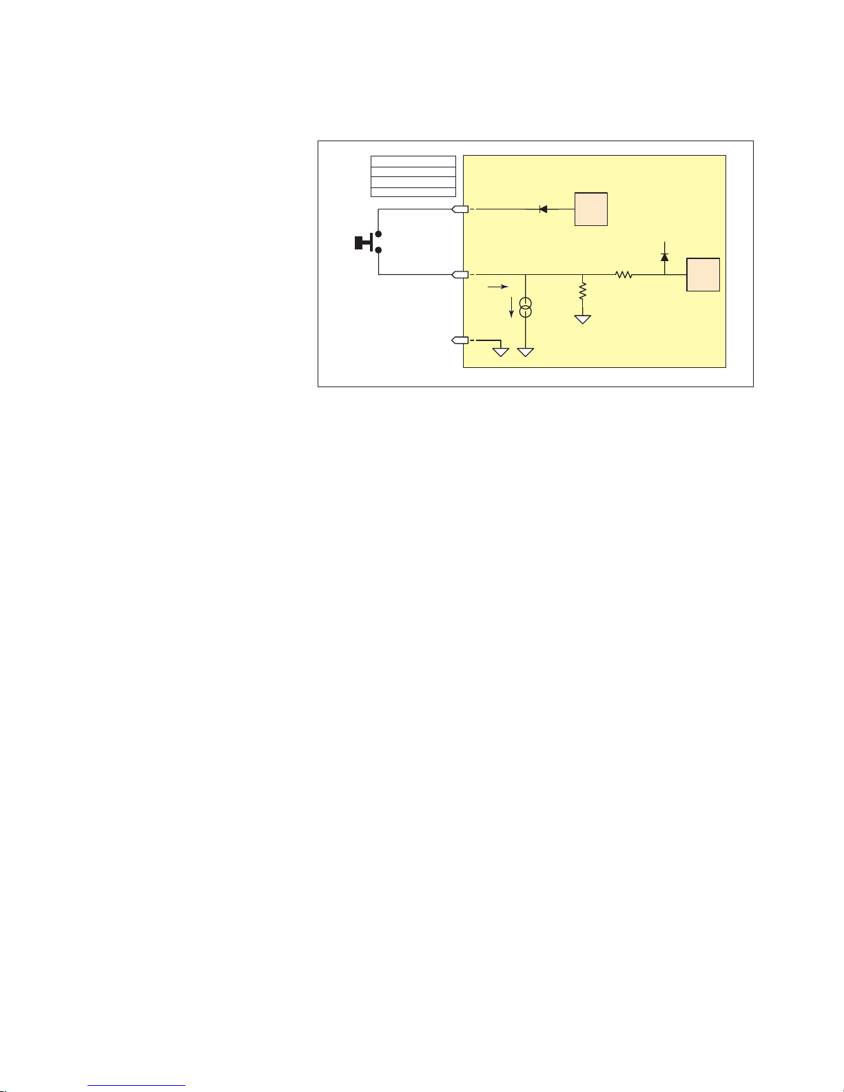
Input Interface Example - Switch Input Example (Sourcing Input)
Switch Input, Sourcing
Internal
pull-up
voltage
detect
logic
40 - 135 uA
24.9k ohms
100k ohms
3.3 V
The internal pull-up voltage
cannot provide output
current / voltage
IOPWR
IOx
IOGND
Iih
MForce Plus
2
Vih = 2.31 V
Vil = 0.99 V
Threshold (nom) = 1.5 V
Iih = -1.24 mA
The following circuit example shows a switch connected between an I/O point and a voltage supply which will
source the input to perform a function.
Code Sample
Figure 2.4.10 Sourcing Input Example using a Push Button Switch
For the code sample, the switch will be set up as a Soft Stop sourcing input, active when HIGH.
When pressed, the switches will stop the motor.
S1=5,1,1 ‘set IO point 1 to be a Soft Stop input, active when HIGH,
‘sourcing
SL 200000 ‘enter this to slew the motor at 200000 µsteps/sec
When the switch is depressed the motor will decelerate to a stop.
2-30
Motion Control MForce MicroDrive Hardware Manual Revision R112706
Page 61
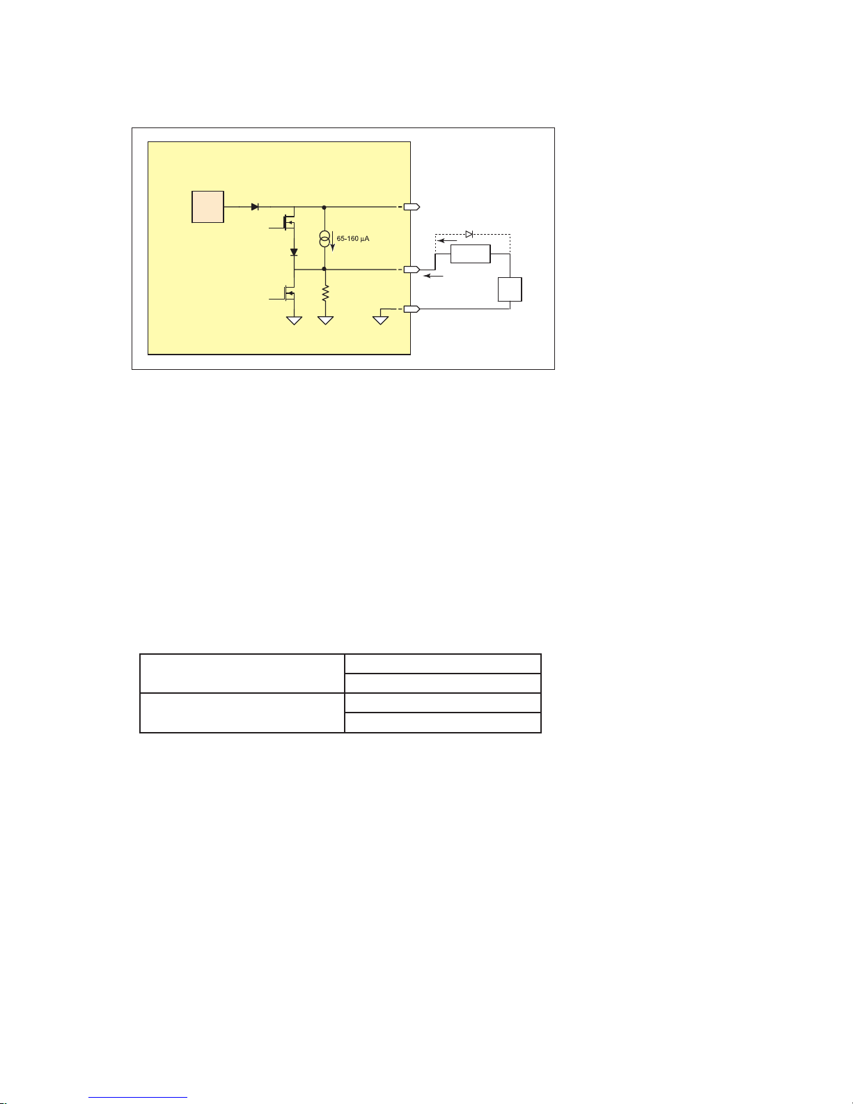
Output Interface Example (Sinking Output)
Internal
pull-up
voltage
The internal pull-up voltage
cannot provide output
current / voltage
24.9k ohms
Sinking Output Equivalent Circuit
always
off
switched
IOPWR
IOx
IOGND
MForce Plus
2
load current, sinking
up to
24 V
LOAD
Sinking Output
+
Diode recommended for
inductive loads
The following circuit example shows a load connected to an I/O point that will be configured as a sinking
output.
Figure 2.4.11: Sinking Output Example
Code Sample
For the code sample, the load will be an LED. The I/O point will be configured such that the LED will be
unlit while the velocity is changing. Use the switch set-up from the previous input, modified to be sinking,
example to soft stop the motor.
S1=5,0,0 ‘set IO point 1 to be a Soft Stop input, active when LOW,
‘sinking.
S1=20,0,0 ‘set IO point 2 to be a Velocity Changing output, active
‘when LOW
SL 2000000 ‘enter this to slew the motor at 200000 µsteps/sec
While the motor is accelerating the LED will be dark, but will light up when the motor reaches a constant
velocity. When the Soft Stop switch is depressed the motor will begin to decelerate, the LED will go dark
again while velocity is changing.
S1=16,1,0
Output, Active HIGH, Sinking
S1=16,1,1
Output, Active LOW, Sourcing
O1=1 (Sink OFF, Hi-Z)
O1=0 (Sink ON)
O1=1 (Sink ON)
O1=0 (Sink OFF, Hi-Z)
Part 2: Connections and Interface
2-31
Page 62

Output Interface Example (Sourcing Output)
Internal
pull-up
voltage
The internal pull-up voltage
cannot provide output
current / voltage
24.9k ohms
Sourcing Output Equivalent Circuit
always
off
switched
IOPWR
IOx
IOGND
MForce Plus
2
LOAD
12 to
24 V
+
load current, sourcing
Sourcing Output
The following circuit example shows a load connected to an I/O point that will be configured as a sourcing
output.
Figure 2.4.12: Sourcing Output Example
Code Sample
For the code sample, the load will be a relay. The output will be configured to be a General Purpose user output that will be set active when a range of motion completes.
Enter EX 100 to execute the program, the motion will occur and the output will set high.
2-32
******Setup Variables******
S1=16,1,1 ‘set IO point 1 to be a user output, active when HIGH,
‘sourcing.
******Program******
PG 100 ‘Enter program at address 100
MR 2000000 ‘Move some distance in the positive direction
H ‘Hold execution until motion completes
MR -1000000 ‘Move some distance in the negative direction
H ‘Hold execution until motion completes
O1=1 ‘Set output 1 HIGH
S1=16,1,1
Output, Active HIGH, Sourcing
S1=16,0,1
Output, Active LOW, Sourcing
O1=1 (Source ON)
O1=0 (Source OFF, Hi-Z)
O1=1 (Source OFF, Hi-Z)
O1=0 (Source ON)
Motion Control MForce MicroDrive Hardware Manual Revision R112706
Page 63

Dedicated Digital I/O - Enhanced I/O Set
Step Clock
Direction
Channel A
Channel B
CW
CCW
Step/Direction Function
Quadrature Function
Up/Down Function
Input: S<7-8>=33, <active state>
Output: S<7-8>=49,<active state>
Input: S<7-8>=34, <active state>
Output: S<7-8>=50,<active state>
Input: S<7-8>=35, <active state>
Output: S<7-8>=51,<active state>
IOGND
VinMax = +5 V
Vin Hi = 1.86 V
Vin Low = 0.9 V
Iin Hi = 1 mA
IinLow = -0.8 mA
Vo Min = 2 V
Vo Max = 5 V
Iosc Min = 35 mA
Iosc Max = 250 mA
STEP_IO
T
R
DIR_IO
T
R
ENABLE SDIO
Step In
Step Out
Dir In
Dir Out
Step Clock/Channel A/Clock Up
Direction/Channel B/Clock Down
MForce
When used as an input a
10kΩ Bias resistor is
required.
Step/Direction/Clock I/O
These dedicated I/O lines are used to
receive clock inputs from an external device or
provide clock outputs to an external device
such as a counter or a second MForce
MicroDrive in a system.
The Clock I/O can be configured as one of three clock types using the
S7 and S8 variable:
1. Step/Direction
2. Quadrature
3. Up/Down
Step/Direction
The Step/Direction function
would typically be used to receive
step and direction instructions
from a second system MForce
or secondary controller. When
configured as outputs the MForce
can provide step and direction
control to another system drive
for electronic gearing applications.
Quadrature
The Quadrature clock function
would typically be used for
following applications where
Figure 2.4.13: MForce MicroDrive Clock Functions
the MForce would either be a master or slave in an application that would require two MForce
MicroDrives to move the same distance and speed.
Up/Down
The Up/Down clock would typically be used in a dual-clock direction control application, or to
increment/decrement an external counter.
NOTE: Advanced
I/O interface circuit
diagrams and
application examples are
available in the I/O Application
Guide Appendix.
NOTE: When
using the MForce
MicroDrive2 with the
external encoder
option, the step an direction
I/O are not available! These I/
O points become Index + and
Index -. See the Closed Loop
Control Appendix for encoder
connection and conguration
information.
Part 2: Connections and Interface
Figure 2.4.14: Step Direction I/O Equivalent Circuit
WARNING: The
Clock I/O and
Capture/Trip
I/O are TTL Level
compatible. DO NOT Exceed
+5VDC!
2-33
Page 64

Capture /Trip
IOGND
MForce Plus
VinMax = +5 V
Vin Hi = 1.86 V
Vin Low = 0.9 V
Iin Hi = 1 mA
IinLow = -0.8 mA
Vo Min = 2 V
Vo Max = 5 V
Iosc Min = 35 mA
Iosc Max = 250 mA
CAPT_IN
TRIP_OUTT
R
ENABLE TO
Trip Out
Capt In
Capture In/Trip Out
The Capture Input/Trip Output point is a high speed I/O point which can be used for time critical events in motion
applications.
Capture Input
When configured as a capture input I/O point 13 has programmable filtering with a range of 50nS to 12.9
µS and has a resolution of 32 bits. The capture input needs to be pulled up to TTL using a 10k ohm resistor.
To configure the Capture input
S13=60,<0/1> ‘configure IO13 as a capture input, <active HIGH/LOW>
FC <0-9> ‘set input filtering to <range>
Trip Output
When configured as a trip output I/O 13 trip speed is 150 nS with 32 bit resolution.
To configure the Trip output
S13=61,<0/1> ‘configure IO13 as a trip output, <active HIGH/LOW>
CW=10 ‘set the trip output pulse width to 500 nS
2-34
Figure 2.4.15: Capture/Trip I/O Equivalent Circuit
Motion Control MForce MicroDrive Hardware Manual Revision R112706
Page 65
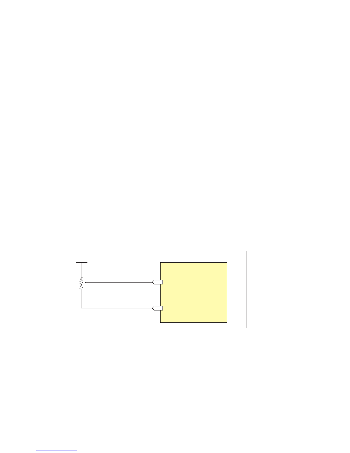
Interfacing the Analog Input
+V (0-5VDC/0-10VDC)
10 k Ohm Potentiometer
Voltage Mode
MForce Plus Motion Control
Analog Input
Ground
S5=9,0 'set input +VDC range to 0 - +5 VDC
S5=9,1 'set input +VDC range to 0 - +10 VDC
The analog input of the MForce MicroDrive is configured from the factory as a 0 to 5V, 10 bit resolution
input (S5=9). This offers the user the ability to receive input from temperature, pressure, or other forms of sensors, and then control events based upon the input.
The value of this input will be read using the I5 instruction, which has a range of 0 to 1023, where 0 = 0 volts
and 1024 = 5.0 volts. The MForce MicroDrive may also be configured for a 4 to 20 mA or 0 to 20 mA Analog
Input (S5 = 10).
Sample Usage
‘***********Main Program**************
S5=9,0 ‘set analog input to read variable voltage (0 to +5VDC)
PG 100 ‘start prog. address 100
LB A1 ‘label program A1
CL A2, I5<500 ‘Call Sub A2, If I5 is less than 500
CL A3, I5>524 ‘Call Sub A3, If I5 is greater than 524
BR A1 ‘loop to A1
‘***********Subroutines**************
LB A2 ‘label subroutine A2
MA 2000 ‘Move Absolute 2000 steps
H ‘Hold program execution until motion ceases
RT ‘return from subroutine
LB A3 ‘label subroutine A3
MA -2000 ‘Move Absolute -2000 steps
H ‘Hold program execution until motion ceases
RT ‘return from subroutine
E ‘End
PG ‘Exit program
Figure 2.4.16: Analog Input - Voltage Mode
Part 2: Connections and Interface
2-35
Page 66

Current Mode
MForce Plus Motion Control
Analog Input
Ground
S5=10,0 'set input I range to 0 to 20mA
S5=10,1 'set input I range to 4 to 20mA
4 - 20 mA, 0 - 20 mA Source
Source Ground
Figure 2.4.17: Analog Input - Current Mode
2-36
Motion Control MForce MicroDrive Hardware Manual Revision R112706
Page 67

Appendices
TM
FORCE
MICRO DRIVE
MOTION CONTROL
Appendix A: Recommended Power and Cable Configurations
Excellence in Motion
TM
Appendix B: I/O Application Guide
Appendix C: Optional IMS Encoders
Appendix D: Optional Cables and Cordsets
Appendix E: IMS Enhanced Torque Stepping Motors
Appendices
A-1
Page 68

A-2
MForce MicroDrive Motion Control Hardware Manual Revision R112706
Page 69

ap p en d ix A
Shield to Earth Ground
on Supply End Only
π Type RFI Filter
≥ Required Current
120 or 240 VAC
Dependent on
Power Supply
Power Supply
+
-
To Cable A
DC Volts Out
Shielded Twisted Pair
(Wire Size from
MDrive Supply Cable AWG Table)
Cable Length
as required
NOTE:
Connect the cable illustrated
in Example A to the output of
the Power Supply
Shield to Earth Ground
on Supply End Only
DC Voltage from
Power Supply
500 µf
Per Amp
+
-
Ferrite
Beads
π Type RFI Filter
≥ Required Current
+
-
To MDrive
Shielded Twisted Pair
(Wire Size from
MDrive Supply Cable AWG Table)
Cable Length
less than 50 Feet
Shield to Earth Ground
on Supply End Only
π Type RFI Filter
≥ Required Current
Transformer - 10 to 28 VAC RMS for 48 VDC Systems
20 to 48 VAC RMS for 75 VDC Systems
Full Wave Bridge
+
-
To Cable A
Shielded Twisted Pair
(Wire Size from
MDrive Supply Cable AWG Table)
Cable Length
as required
NOTE:
Connect the cable illustrated
in Example A to the output of
the Full Wave Bridge
Recommended Power and Cable Configurations
Cable length, wire gauge and power conditioning devices play a major role in the performance of your MForce.
Example A demonstrates the recommended cable configuration for DC power supply cabling under 50 feet
long. If cabling of 50 feet or longer is required, the additional length may be gained by adding an AC power
supply cable (see Examples B & C).
Correct AWG wire size is determined by the current requirement plus cable length. Please see the MForce Supply Cable AWG Table at the end of this Appendix.
Example A – Cabling Under 50 Feet, DC Power
NOTE: These
recommendations
will provide optimal
protection against EMI and
RFI. The actual cable type,
wire gauge, shield type and
filtering devices used are
dependent on the customer’s
application and system.
NOTE: The length of
the DC power supply
cable to an MForce
should not exceed
50 feet.
NOTE: These
recommendations
will provide optimal
protection against EMI and
RFI. The actual cable type,
wire gauge, shield type and
filtering devices used are
dependent on the customer’s
application and system.
NOTE: Always use
Shielded/Twisted
Pairs for the MForce
DC Supply Cable
and the AC Supply Cable.
Figure A.1: DC Cabling - Under 50 Feet
Example B – Cabling 50 Feet or Greater, AC Power to Full Wave Bridge
Figure A.2: DC Cabling - 50 Feet or Greater - AC To Full Wave Bridge Rectifier
Example C – Cabling 50 Feet or Greater, AC Power to Power Supply
Appendices
Figure A.3: AC Cabling - 50 Feet or Greater - AC To Power Supply
A-3
Page 70

Recommended IMS Power Supplies
IMS unregulated linear and unregulated switching power supplies are the best fit for IMS drive products.
IP402 Unregulated Linear Supply
Input Range
120 VAC Versions ...........................................................................................102-132 VAC
240 VAC Versions ...........................................................................................204-264 VAC
Output (All Measurements were taken at 25˚C, 120 VAC, 60 Hz)
No Load Output Voltage ........................................................................ 39 VDC @ 0 Amps
Half Load Output .................................................................................. 30 VDC @ 2 Amps
Full Load output .................................................................................... 25 VDC @ 4 Amps
IP404 Unregulated Linear Supply
Input Range
120 VAC Versions ...........................................................................................102-132 VAC
240 VAC Versions ...........................................................................................204-264 VAC
Output (All Measurements were taken at 25˚C, 120 VAC, 60 Hz)
No Load Output Voltage ........................................................................ 43 VDC @ 0 Amps
Half Load Output .................................................................................. 32 VDC @ 3 Amps
Full Load Output ...................................................................................26 VDC @ 6 Amps
ISP200-4 Unregulated Switching Supply
Input Range
120 VAC Versions ...........................................................................................102-132 VAC
240 VAC Versions ...........................................................................................204-264 VAC
Output (All Measurements were taken at 25˚C, 120 VAC, 60 Hz)
No Load Output Voltage ........................................................................ 41 VDC @ 0 Amps
Continuous Output Rating .................................................................... 38 VDC @ 2 Amps
Peak Output Rating ...............................................................................35 VDC @ 4 Amps
Recommended Power Supply Cabling
MForce Plus Supply Cable AWG Table
Length (Feet) 10 25 50* 75* 100*
Minimun AWG 20 20 18 18 16
Length (Feet) 10 25 50* 75* 100*
Minimun AWG 20 18 16 14 14
*Use the alternative methods illustrated in examples B
and C when cable length is ≥ 50 feet. Also, use the same
current rating when the alternate AC power is used.
Table A.1: Recommended Supply Cables
1 Ampere (Peak)
2 Amperes (Peak)
A-4
MForce MicroDrive Motion Control Hardware Manual Revision R112706
Page 71

ap p en d ix B
NPN Input, Sinking
Internal
pull-up
voltage
detect
logic
24.9k ohms
100k ohms
3.3 V
GND
Iil
65 - 160 uA
MForce Sinking Input
Equivalent Circuit
IOx
Vih = 2.31 V
Vil = 0.99 V
Threshold (nom) = 1.5 V
Iil = 100 µA
up to
24 V
NPN
+
Standard I/O Set Interfacing and Application
NPN Sinking Input
Application Example
Figure B.1: NPN Interface to an MForce Sinking Input
I/O Application Guide
Proximity sensor will operate as a +Limit. When active LOW will index the motor to a specified
position.
‘[VARIABLES]
S1=2,0,0 ‘set IO1 to Limit+, Active LOW, sinking
‘[PROGRAMS]
PG 100 ‘enter program mode at address 100
LB AA ‘label program AA
MR 200000000 ‘move relative x distance
H ‘hold program execution until move completes
CL AB , I1 = 0 ‘call subroutine AB if I1 = 0 (limit reached)
BR AA , I1 = 1 ‘branch to AA if I1=1
LB AB ‘Label Sub AB
PR “Error 83, Positive Limit Reached”
ER=0
MA - 10000 ‘Absolute move to Pos. -10000
H ‘hold program execution until move completes
E ‘end program
PG ‘exit program.
‘[END]
Appendices
A-5
Page 72

PNP Sourcing Input
PNP Input, Sourcing
Internal
pull-up
voltage
detect
logic
40 - 135 uA
24.9k ohms
100k ohms
3.3 V
The internal pull-up voltage
cannot provide output
current / voltage
IOx
GND
Iih
MForce Sourcing Input Equivalent
Vih = 2.31 V
Vil = 0.99 V
Threshold (nom) = 1.5 V
Iih = -1.24 mA
up to
24 V
PNP
+
Figure B.2: PNP Interface to a Sourcing Input
Application Example
Will use this input as a general purpose input which will run a motion subroutine when HIGH.
‘[VARIABLES]
S1=0,1,1 ‘set IO1 Gen Purpose User, active HIGH, src
S2=0,1,1 ‘set IO1 Gen Purpose User, active HIGH, src
‘[PROGRAMS]
‘*****Main Program*****
PG 100
LB AA
CL SA,I1=1 ‘call sub SA if IO1=1
CL SB,I2=1 ‘call sub SB if IO2=1
BR AA
‘******Subroutines*******
LB SA ‘Subroutine will perform some motion
MR 200000
H
MR -200000
H
BR SA,I1=1 ‘conditional branch to beginning of sub
BR AA,I1=0 ‘Branch to main program if IO1=0
RT
LB SB ‘Subroutine will perform some motion
MR 10000
H
MR -10000
H
BR SB,I2=1 ‘conditional branch to beginning of sub
BR AA,I2=0 ‘Branch to main program if IO1=0
RT
E
PG
‘[END]
A-6
MForce MicroDrive Motion Control Hardware Manual Revision R112706
Page 73

Sinking Output
Internal
pull-up
voltage
24.9k ohms
Sinking Output Equivalent Circuit
always
off
switched
IOx
GND
MForce Plus
Sinking Output
*External Resistor may be needed to
limit output sink current to 600mA
up to
24 V
+
IO1
IO2
IO3
IO4
GND
S1 = 16,0
S2 = 4,1,1
S3 = 2,0,0
S4 = 3,0,0
GO
+ LIMIT
- LIMIT
LOAD
PNP
up to
+24 V
+
S Parameter Settings
Figure B.3: Sinking Output to Relay
Application Example
Active LOW Output will be opem a relay, useful for Fault.
‘[VARIABLES]
S1=19,0,0 ‘Configure IO 1 as a Fault output.
NOTE: On the
Standard MForce
Plus, when congured
set is sinking ONLY! The Plus
as outputs, the I/O
2
Models add the functionality of
I/O Power, which enables the
user to use all the outputs, both
Standard and Enhanced, as
Sinking or Sourcing.
Mixed Input/Output Example
Appendices
Figure B.4: Mixed Output Example- Standard I/O Set
A-7
Page 74

Enhanced I/O Set Interfacing and Application
Internal
pull-up
voltage
detect
logic
24.9k ohms
100k ohms
3.3 V
The internal pull-up voltage
cannot provide output
current / voltage
IOPWR
IOGND
Iil
65 - 160 uA
MForce Plus2
IOx
Vih = 2.31 V
Vil = 0.99 V
Threshold (nom) = 1.5 V
Iil = 100 µA
NPN Input, Sinking
Sinking Input Equivalent Circuit
NPN
12 to
24 V
+
PNP Input, Sourcing
Internal
pull-up
voltage
detect
logic
40 - 135 uA
24.9k ohms
100k ohms
3.3 V
The internal pull-up voltage
cannot provide output
current / voltage
IOPWR
IOx
IOGND
Iih
MForce Plus
2
Vih = 2.31 V
Vil = 0.99 V
Threshold (nom) = 1.5 V
Iih = -1.24 mA
PNP
12 to
24 V
NPN Sinking Input
Figure B.5: NPN Sinking Input on an MForce Plus2 Motion Control
Application Example
Sensor using the HOME function.
PNP Sourcing Input
Application Example
A-8
‘[VARIABLES]
S2=1,1,0 ‘Configure IO2 as a Home Input, active HIGH, sinking.
Enter to IMS Terminal in Immediate mode or in a Program
HM 1 ‘Slew at VM - until IO2 = 1, Creep off + at VI
Sensor using the Jog+ function.
JE=1 ‘Enable Jog function
S11=7,1,1 ‘Configure IO11 as a Jog+ Input, active HIGH, sourcing
Figure B.6: PNP Sourcing Input on an MForce Plus2 Motion Control
MForce MicroDrive Motion Control Hardware Manual Revision R112706
Page 75

Sour cin g Output
Internal
pull-up
voltage
The internal pull-up voltage
cannot provide output
current / voltage
24.9k ohms
Sourcing Output Equivalent Circuit
Sourcing Input Equivalent Circuit
always
off
switched
IOPWR
IOx
IOGND
MForce Plus
2
load current, sourcing
Sourcing Output
Sourcing Input
Internal
pull-up
voltage
detect
logic
40 - 135 uA
24.9k ohms
100k ohms
3.3 V
The internal pull-up voltage
cannot provide output
current / voltage
IOPWR
IOx
IOGND
Iih
MForce Plus
2
#2
MForce Plus
2
#1
Application Example
This application example will illustrate two MForce Plus2 units in a system. In the program example MForce
Plus2 #1 will be configured as a Fault Output, which when HIGH will trip an input on MForce Plus2 #2
which will be configured as a Pause Input.
MForce #1
Figure B.7: Sourcing Output to Sourcing Input
S9=18,1,1 ‘Configure IO9 as a Fault output, active HIGH, sourcing
MForce #2
S9=6,1,1 ‘Configure IO9 as a Pause Input, active HIGH, sourcing.
Appendices
A-9
Page 76
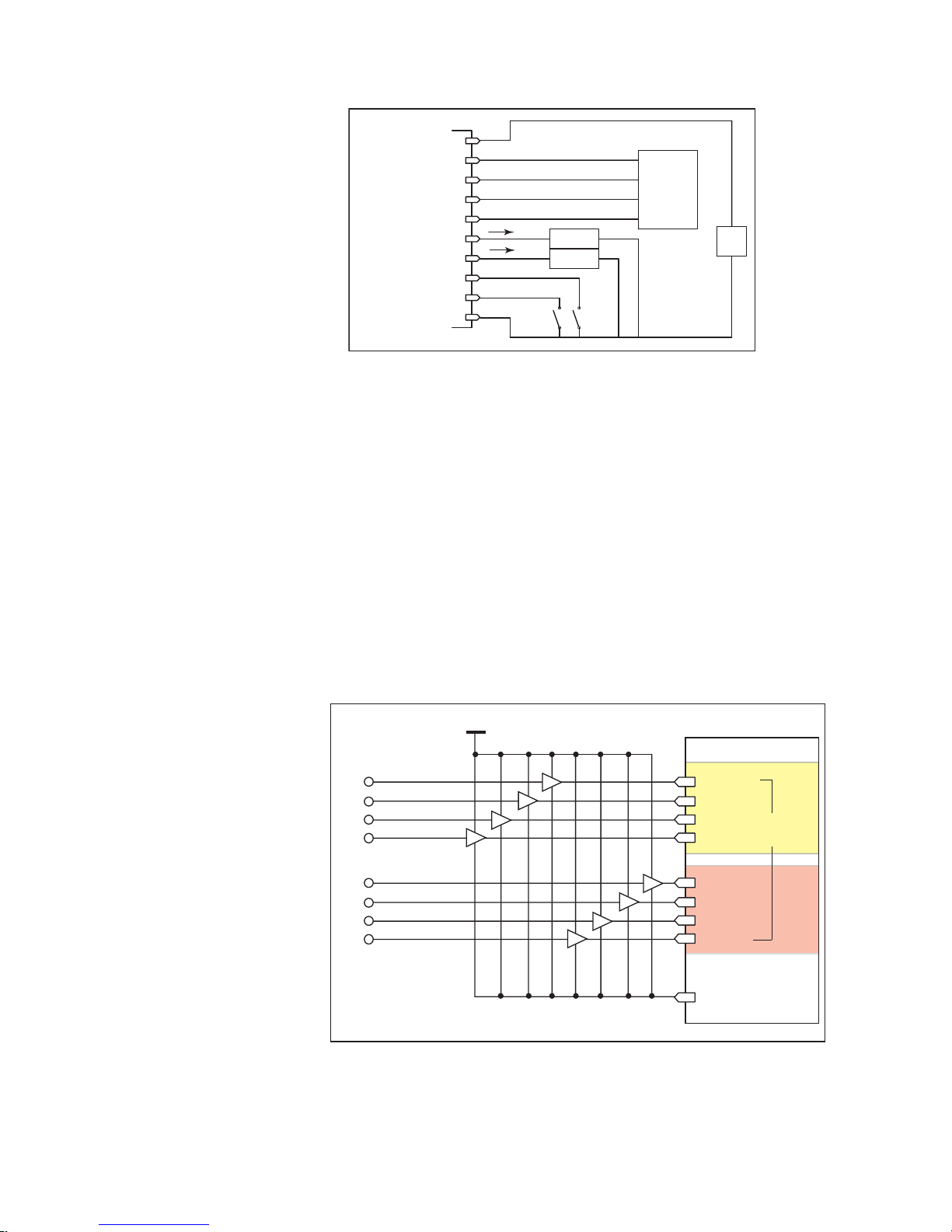
Mixed Input/Output Example
IO1
IO2
IO3
IO4
IOGND
S1 = 17,0,0
S2 = 19,0,0
S3 = 7,1,1
S4 = 8,1,1
STALL
JOG +
JOG -
LOAD
MOVING
IO9
IO10
IO11
IO12
S9 = 16,1,1
S10 = 16,1,1
S11 = 2,0,0
S12 = 3,0,0
+ LIMIT
- LIMIT
+12 to
+24 V
IOPWR
LOAD
OUT (PNP)
OUT (PNP)
IN (w / pullup)
IN (w / pullup)
PLC
+
+5 VDC
MDrivePlus Motion Control
IO1
IO2
IO3
IO4
IO9
IO10
IO11
IO12
GND
STANDARDENHANCED
LSB LSB
MSB
IL
IN
LSB
MSB MSB
IH
Figure B.8: Mixed Input/Output Example - Enhanced I/O
Interfacing Inputs as a Group Example
The MForce inputs may read as a group using the IL. IH and IN keywords. This will display as a decimal between 0
to 15 representing the 4 bit binary number (IL, IH) or as a decimal between 0 and 255 representing the 8 bit binary
number on the MForce Plus2 models. The IN keyword will function on the standard MForce but will only read
inputs 1 - 4. Inputs will be configured as user inputs (S<point>=0).
Standard MForce Plus Motion Control
PR IN ‘Reads Inputs 4(MSB) through 1(LSB)
PR IN ‘Reads Inputs 4(MSB) through 1(LSB)
Enhanced MForce Plus2
PR IL ‘Reads Inputs 4(MSB) through 1(LSB)
PR IH: ‘Reads Inputs 12(MSB) through 9(LSB)
PR IN: ‘Reads Inputs 12(MSB) - 9 amd 4 - 1(LSB)
A-10
Figure B.9: TTL Interface to an Input Group
MForce MicroDrive Motion Control Hardware Manual Revision R112706
Page 77

Interfacing Outputs as a Group Example
MDrivePlus Motion Control
IO1
IO2
IO3
IO4
IO9
IO10
IO11
IO12
STANDARDENHANCED
LSB
LSB
MSB
OL
OT
LSB
MSB
MSB
OH
+5 to +24 VDC
The MForce inputs may be written to as a group using the OL, OH and OT keywords. This will set the outputs
as a binary number representing the decimal between 0 to 15 representing the 4 bit binary number (OL, OH)
or as an 8 bit binary number representing the decimal 0 to 255 on the Expanded MForce Plus2 models. The OT
keyword will function on the standard MForce but will only set inputs 1 - 4. Outputs will be configured as user
outputs (S<point>=16).
Standard MForce Plus Motion Control
OL=3 ‘set the binary state of the standard I/O to 0011
OT=13 ‘set the binary state of the standard I/O to 1101
Enhanced MForce Plus2
OL=5 ‘set the binary state of the standard I/O to 0101
OH=9 ‘set the binary state of the expanded I/O to 1001
OT=223 ‘set the binary state of the combined I/O to 1101 1111
Figure B.10: Outputs Interfaced to LED’s as a Group
Output Bit Weight Examples
Enhanced (Plus2) Standard
I/O Set
OL=13
OT=13
OH=9 NOT ADDRESSED BY OH
OT=223
IO12
(MSB)
Table B.1: Output Bit Weight Examples - Outputs set as a group
IO11 IO10 IO9 IO4 IO3 IO2 IO1
NOT AVAILABLE
1 1 0 1
1 0 0 1
1 1 0 1 1 1 1 1
(LSB)
Appendices
A-11
Page 78

ap p en d ix C
P1
Pin 9: Channel B+
Pin 13: Index +
Pin 14: Index -
Pin 10: Channel B Pin 7: Channel A+
Pin 8: Channel A -
Pin 1: No Connect
Pin 2: +5VDC Input
Pin 3: Ground
Pin 4: No Connect
Pin 5: Channel A –
Pin 6: Channel A +
Pin 7: Channel B –
Pin 8: Channel B +
Pin 9: Index –
Pin 10: Index +
246
8
10
13579
Differential
MForce Motion Control Closed Loop Options
Encoder Options
Remote Differential Encoder - MForce MicroDrive Plus
2
The MForce Plus2 models are available with the option of using a remote encoder through the enhanced I/O.
The advantage of using a remote encoder is that the encoder can be stationed directly on the load for increased
accuracy. If ordering with a motor these encoders may be mounted for you at the factory. Only differential
encoders may be used with the MForce Plus2.
Set Up and Configuration
Figure C.1: Connecting a Remote Encoder
Encoders Available from IMS
Line Count Part Number
A-12
General Specifications
Min Typ Max Units
Supply Voltage (VDC) ......................... -0.5 ........................................................... 7 ......................Volts
Supply Current ......................................30............................. 57 .......................... 85 ..................... mA
Output Voltage .................................... -0.5 ......................................................... Vcc ................... Volts
Output Current (Per Channel) ............. -1.0 ........................................................... 5 ....................... mA
Maximum Frequency ................................................................................................................. 100kHz
Inertia ............................................................................................... 0.565 g-cm2 (8.0 x 10⁻⁶ oz-in-sec2)
DIFFERENTIAL
ENCODER
100 EA
200 EB
250 EC
256 EW
400 ED
500 EH
512 EX
1000 EJ
1024 EY
Table C.1: Available Encoder Line Counts, Part Numbers and Pin Configurations
MForce MicroDrive Motion Control Hardware Manual Revision R112706
Page 79

C
t1
t2
Po
X
Y
Z
2.4 V
0.4 V
2.4 V
0.4 V
2.4 V
0.4 V
2.4 V
0.4 V
2.4 V
0.4 V
2.4 V
0.4 V
Channel
A
+
Channel B +
Index +
Channel
A
-
Channel B -
Index -
Rotation:
CW – B Leads A
CCW – A Leads B
Temperature
Operating ................................................................................................................ -40 to +100° C
Storage ..................................................................................................................... -40 to +100° C
Humidity ............................................................................................................ 90% (non-condensing)
Encoder Signals
Differential Encoder
Figure C.2: Differential Encoder Signals
Note: Rotation is as viewed from the cover side.
(C) One Cycle: 360 electrical degrees (°e)
(X/Y) Symmetry: A measure of the relationship between X and Y, nominally 180°e.
(Z) Quadrature: The phase lag or lead between channels A and B, nominally 90°e.
(Po) Index Pulse Width: Nominally 90°e.
Characteristics
Parameter Symbol Min Typ Max Units
Cycle Error ................................................................................................ 3 .................... 5.5 .................°e
Symmetry ............................................................................. 130 ............ 180 .................. 230 ................°e
Quadrature ............................................................................ 40 .............. 90 ...................140 ................°e
Index Pulse Width ..............................................Po .............. 60 .............. 90 ................... 120 ................°e
Index Rise After CH B or CH A fall ................... t1 ..............-300 ...........100 ..................250 ................ns
Index Fall After CH A or CH B rise ................... t2 ............... 70 ............. 150 .................1000 ...............ns
Over recommended operating range. Values are for worst error over a full rotation.
Appendices
A-13
Page 80

Encoder Cables
IMS Differential Encoder Cable (36” leads) ..................................................................... ED-CABLE-2
Recommended Encoder Mating Connectors
IMS recommends the following mating connectors (or equivalent) if you make your own cables.
Differential Encoder
Tyco Electronics Connector with 10 Preloaded IDC Pins* ................................................ 102694-3
Shell with Polarizing Key ......................................................................................... 102537-3
Back Cover .............................................................................................................. 102536-3
Tyco Electronics 10 Pin IDC Ribbon Cable Connector ....................................................499997-1
3M 28 AWG x 0.5 x 10 Conductor Ribbon Cable .............................................................. 3365/10
*For AWG 22 to 28 wires.
A-14
MForce MicroDrive Motion Control Hardware Manual Revision R112706
Page 81
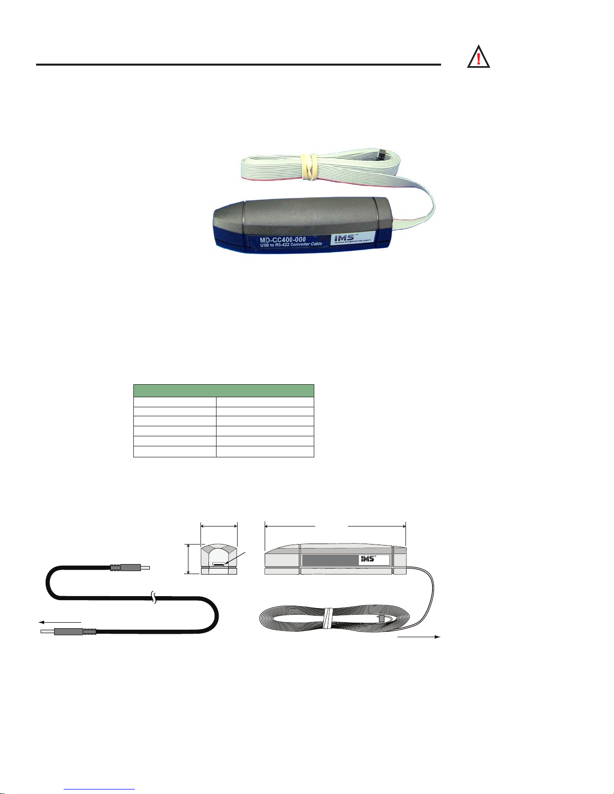
ap p en d ix D
10-Pin IDC Connector
Cable Length 6.0 ft (1.8 m)
MD-CC400-000
USB to RS-422 Converter Cable
www.imshome.com
USB Cable
Length 6.0 ft (1.8 m)
1.0 in
(25.0 mm)
3.75 in
(95.0 mm)
0.875 in
(22.0 mm)
USB
To MForce
To PC USB
Communications Converter Cables
USB to 10-Pin IDC (MD-CC400-000)
The MD-CC400-000 is an in-line USB to RS-422 converter with integrated 10-pin IDC cable. This product
is used to communicate to a single
Motion Control MForce. The included
components will allow you to connect
the USB port of a PC* directly to the
10-Pin IDC Connector located at P2.
Supplied Components: MD-CC400000 Communications Converter
Cable, USB Cable, USB Drivers, IMS
Terminal Interface Software.
10-Pin Locking Wire Crimp
Adapter
An optional pin adapter is available to convert the 10-pin IDC connector on the Communications Converter Cable to a 10-pin friction
lock wire crimp interface used on the Plus2 units.
Adapter Part # ....................................................... MD-ADP-H
Optional Cables and Cordsets
Figure D.1: MD-CC400-000
WARNING! DO NOT
connect or disconnect
the MD-CC400000 Communications Converter
Cable from MForce while power is
applied!
* If your PC is already equipped with RS-422, the MD-CC400-000 cable is not required.
Electrical Specifications
MD-CC400-000 Specications
BAUD Rate Up to 115 kbps
Connectors:
USB
RS-422 Side 10 Pin 2mm IDC
Ribbon Cable Length 6 feet (1.8 meters)
Power Requirement Power from USB
Table D.1: MD-CC400-000 Electrical Specifications
Mechanical Specifications
Figure D.2: MD-CC400-000 Mechanical Specifications
Appendices
A-15
Page 82

Note: An Interactive
Tutorial covering the
installation of the
Cable/VCP drivers are located
on the IMS Web Site at http://
www.imshome.com/tutorials.
html.
Installation Procedure for the MX-CC400-000
These Installation procedures are written for Microsoft Windows XP Service Pack 2. Users with earlier versions
of Windows please see the alternate installation instructions at the IMS web site (http://www.imshome.com).
The installation of the MD-CC400-000 requires the installation of two sets of drivers:
Drivers for the IMS USB to RS-422 Converter Hardware.
Drivers for the Virtual Communications Port (VCP) used to communicate to your IMS Product.
Therefore the Hardware Update wizard will run twice during the installation process.
The full installation procedure will be a two-part process: Installing the Cable/VCP drivers and Determining
the Virtual COM Port used.
Installing the Cable/VCP Drivers
1) Plug the USB Converter Cable into the USB
port of the MD-CC400-000.
2) Plug the other end of the USB cable into an
open USB port on your PC.
3) Your PC will recognize the new hardware and
open the Hardware Update dialog.
4) Select “No, not this time” on the radio
buttons in answer to the query “Can
Windows Connect to Windows Update to
search for software?” Click “Next” (Figure
F.4).
5) Select “Install from a list or specific location
(Advanced)” on the radio buttons in answer
to the query “What do you want the wizard
to do?” Click “Next” (Figure F.5).
Figure D.3: Hardware Update Wizard
6) Select “Search for the best driver in these locations.”
(a) Check “Include this location in the search.”
(b) Browse to the Product CD [Drive Letter]:\ Cable_
(c) Click Next (Figure F.6).
A-16
Figure D.4: Hardware Update Wizard Screen 2
Drivers\MD CC40x000_DRIVERS.
MForce MicroDrive Motion Control Hardware Manual Revision R112706
Page 83

Figure D.5: Hardware Update Wizard Screen 3
7) The drivers will begin to copy.
8) On the Dialog for Windows Logo Compatibility Testing, click “Continue Anyway” (Figure F.7).
9) The Driver Installation will proceed. When the Completing the Found New Hardware Wizard
dialog appears, Click “Finish” (Figure F.8).
10) Upon finish, the Welcome to the Hardware Update Wizard will reappear to guide you through the
second part of the install process. Repeat steps 1 through 9 above to complete the cable installation.
11) Your IMS MD-CC400-000 is now ready to use.
Figure D.6: Windows Logo Compatibility
Testing
Figure D.7: Hardware Update Wizard Finish
Installation
Appendices
A-17
Page 84

Determi ning the Vir tual COM Port (VCP)
The MD-CC400-000 uses a Virtual COM Port to communicate through the USB port to the MForce. A VCP
is a software driven serial port which emulates a hardware port in Windows.
The drivers for the MD-CC400-000 will automatically assign a VCP to the device during installation. The
VCP port number will be needed when IMS Terminal is set up in order that IMS Terminal will know where to
find and communicate with your IMS Product.
To locate the Virtual COM Port.
1) Right-Click the “My Computer” Icon and select “Properties”.
2) Browse to the Hardware Tab (Figure D.8), Click the Button labeled “Device Manager”.
3) Look in the heading “Ports (COM & LPT)” IMS USB to RS422 Converter Cable (COMx) will
be listed (Figure D.9). The COM # will be the Virtual COM Port connected. You will enter this
number into your IMS Terminal Configuration.
Figure D.8: Hardware Properties
Figure D.9: Windows Device Manager
Prototype Development Cables
16-Pin Locking Wire Crimp ......................................................................................PD16-1417-FL3
Single or Multi-Drop Communications .....................................................................PD10-1434-FL3
4-Pin Locking Wire Crimp (Motor Connection) .......................................................PD04-MF17-FL3
A-18
MForce MicroDrive Motion Control Hardware Manual Revision R112706
Page 85

PD16-1417-FL3 — Power and I/O
Pair #1
Pair #2
Pair #3
Pair #4
Pair #5
Pair #6
Pair #7
Pair #8
General Specifications
Length: 10 Feet (3.0 Meters)
Conductor: 22 AWG
Twisted Pairs
Shield: Tinned Copper Braid
Jacket: Gray PVC
Ensure Black-Color pair
match is correct prior
to connecting.
Flying Lead End
To Control Interface
Connector End
Plugs Into MForce P1
Pin 1
The PD16-1417-FL3 is a 10’ (3.0 M) Prototype Development Cable used to connect to the 16-Pin Locking
Wire Crimp Connector. The Connector end plugs into the P1 Connector of the MForce Plus2. The Flying Lead
end connects to a Control Interface such as a PLC and the users motor power supply.
Wire Color Code
Pair Number Color Combination Signal Name
(Expanded I/O)
1
2
3
4
5
6
7
8
Black Power Ground Power Ground 16
Red +V (+12 to +48 VDC) +V (+12 to +48 VDC) 15
Black Direction Index – 14
White Step Clock Index + 13
Black Analog In Analog In 12
Green Capture In/Trip Out Capture In/Trip Out 11
Black I/O 12 Channel B – 10
Blue I/O 11 Channel B + 9
Black I/O 10 Channel A – 8
Yellow I/O 9 Channel A + 7
Black I/O 4 I/O 4 6
Brown I/O 3 I/O 3 5
Black I/O 2 I/O 2 4
Orange I/O 1 I/O 1 3
White I/O GND I/O GND 2
Red I/O Power I/O Power 1
Table D.2: PD16-1417-FL3 Wire Color Codes
Signal Name (Remote
Encoder)
P1 Pin
Number
Figure D.10: PD16-1417-FL3 Prototype Development Cable
Appendices
A-19
Page 86

Note: If using the
PD10-1434-FL3
for a single MForce
System, follow only the setup
instructions for Cable #1.
Additional cables are not
required
Prototype Development Cable PD10-1434-FL3 (All MForce Motion Control)
The PD10-1434-FL3 is used to connect to the 10-pin wire crimp option for interfacing RS-422/485 Communications. It also features an additional cable attached for multi-drop communications systems.
Setup Instructions — Cable #1
Cut crimp pins from Communications Wires and strip insulation back approximately 1/4”.
1.
Connect receive (RX) and transmit (TX) lines as shown in the diagram and table above to your
2.
RS-422/485 Host interface.
Connect Communications Ground line to the Comm Ground of your RS-422/485 Host.
3.
Connect Aux-Power (if used) to the +VDC Output of a +12 to +24 VDC Supply.
4.
Connect the return (GND) of the Aux-Supply to Power Ground of the MForce.
5.
Plug the wire crimp connector of Cable #1 into P2 of the MForce #1.
Setup Instructions — Cable #2 and Subsequent MFor ce MicroDrives
Insert the crimped transmit and receive lines into the 10-Pin wire crimp connector of Cable #1 as
1.
shown in the diagram and table.
Connect communications ground (May be daisy-chained).
2.
Connect Aux-Supply at the +VDC output of the +12 to +24 VDC Supply (May NOT be daisy-
3.
chained).
Plug the wire crimp connector of Cable #2 into P2 of MForce #2
4.
Repeat Steps 1-4 for each additional MForce MicroDrive in the system.
5.
PD10-1434-FL3 Connections
Color
Combination
White/Blue RX+ (Comm Host) TX+ (Pin 1)
Blue/White RX+ (Comm Host) TX- (Pin 4)
White/Orange TX+ (Comm Host) RX+ (Pin 6)
Orange/White TX- (Comm Host) RX- (Pin 3)
Green/White COMM GND (Comm Host) COMM GND (Pin 2)
White/Red AUX-Power (At Supply) AUX-Power (Pin 5)
Color
Combination
White/Blue TX+ (Pin 9 - Cable 1) TX+ (Pin 1)
Blue/White TX- (Pin 10 - Cable 1) TX- (Pin 4)
White/Orange RX+ (Pin 7 - Cable 1) RX+ (Pin 6)
Orange/White RX- (Pin 8 - Cable 1) RX- (Pin 3)
Green/White COMM GND (Comm Host) COMM GND (Pin 2)
White/Red AUX-Power (At Supply) AUX-Power (Pin 5)
Table D.3: PD10-1434-FL3 Wire Color Codes
Flying Lead End
Connections Cable 1
MForce #2 Wire Crimp Connection
Flying Lead End
Connections Cable 2
MForce #1 Wire Crimp
MForce #2 Wire Crimp
Connection
Connection
A-20
MForce MicroDrive Motion Control Hardware Manual Revision R112706
Page 87

+12 to +24 VDC AUXILIARY SUPPLY
COMMUNICATIONS GND ONLY
PD10-1434-FL3 (Cable #1)
+12 to +24 VDC AUXILIARY SUPPLY
COMMUNICATIONS GND ONLY
PD10-1434-FL3 (Cable #2)
MForce #1Mforce #2
Cable #1 will Crossover
RX+
RX TX +
TX -
RX+
RX TX +
TX -
Host MForce
RXRX+
TXTX+
Aux Power +12 to +24 VDC
DO NOT DAISY CHAIN! Each
Line MUST connect to the Power
Supply Output - Ground to Motor
Power Ground NOT COMM GND!
Orange/White Stripe
Pin 8
White/Orange Stripe
Pin 7
Blue/White Stripe
Pin 10
White/Blue Stripe
Pin 9
{
AUX-SUPPLY
+12 to +24 VDC
AUX-SUPPLY
+12 to +24 VDC
Communications
Ground at Host
Communications
Ground
1
3
5
7
9
2
4
6
8
10
Pin
Numbers
Wire Crimp
Connector
Figure D.11: PD10-1434-FL3
Appendices
A-21
Page 88

ap p en d ix E
Ø 0.197 +0/-.0005
(Ø 5.0 +0/-.012)
1.2 ±.02
(30.44 ±0.5)
0.39 ±.04 (9.9 ±1.0)
Ø 0.156 +0/-.001
(Ø 4.0 +0/-.012)
15.75 inches (4
0 cm
)
Optiona
l
Rea
r
Shaft
0.95 ± 0.02
(24.0 ± 0.5)
0.59 ± 0.02
(15.0 ± 0.5)
L
MAX
0.177 ± 0.002
(4.5 ± 0.05 )
0.079 (2.0)
1.39 SQ.
(35.3 SQ.)
1.02 TYP.
(26.0 TYP.)
4X M3
0.138 (3.5)
Deep Min
Ø 0.866 +0/-0.00
2
(Ø 22.0 +0/-0.052
)
Ø 0.197 +0/-0.005
(Ø 5.0 +0/-0.012)
FRONT VIEW
0.620 ±0.005
(15.75 ±0.13)
2X M1.2
0.20 (5.1)
Deep Min
REAR VIEW (Reduced)
blue
green
black
red
Motor Connection
WIRE COLOR PHASE
ØA
ØB
ØA
ØB
Size 14 Enhanced Torque Stepping Motor
General Specifications
Part Number Holding
Torque
oz-in
(N-cm)
M -
1410 - 0.75[X]*
10
(7)
Wiring And Connection
Phase
Current
Number
of Leads
Amps ohms mH oz-in
0.75 4 4.3 4
IMS Enhanced Torque Stepping Motors
Phase
Resistance
Table E.1: Size 14 General Specifications
Phase
Inductance
Detent
Torque
(N-cm)
1.4
(1.0)
Rotor
Inertia
oz-in-sec
(kg-cm2)
0.00017
(0.012)
L
Max
Weight
Length
2
inches
(mm)
1.02
(26)
oz
(g)
4.2
(120)
Figure E.1: Size 14 Wiring and Connection
Mechanical Specifications
Dimensions in Inches (mm)
A-22
Figure E.2: Size 14 Mechanical Specifications
MForce MicroDrive Motion Control Hardware Manual Revision R112706
Page 89

Size 17 Enhanced Torque Stepping Motor
1.67 SQ.
(42.3 SQ.)
4X Ø M3xP0.5
0.177 (4.5) Deep Min
1.22 SQ.
(30.99 SQ.)
Ø 0.866 +0/-0.002
(Ø 22.0 +0/-0.052)
FRONT VIEW
0.75 ±0.005
(19 ±0.13)
2X M2
0.20 (5.1)
Deep Min
REAR VIEW (Reduced)
Ø 0.197 +0/-0.001
(Ø 4.99 +0/-0.012)
0.590 (14.86)
0.55
(14)
11.8 inches (30 cm)
Optional
Rear
Shaft
0.177 ± 0.002
(4.52 ± 0.05)
0.94 ± 0.02
(23.88 ± 0.51)
0.08 (2.03)
L
MAX
0.177 ± 0.002
(4.52 ± 0.05)
Ø
0.197 (
Ø 5.0
)
Flat extends to
rear end bell
black
blue
red
green
Motor Connection
WIRE COLOR PHASE
ØA
ØB
ØA
ØB
General Specifications
Part Number Holding
Torque
oz-in
(N-cm)
M -1713 - 1.5[X]*
M -1715 - 1.5[X]*
M -1719 - 1.5[X]*
*Specify S for Single Shaft; D for Double Shaft
32
(23)
60
(42)
75
(53)
Phase
Current
Amps ohms mH oz-in
Wiring And Connection
Number
of Leads
1.5 4 1.3 2.1
1.5 4 2.1 5.0
1.5 4 2.0 3.85
Phase
Resistance
Phase
Inductance
Table E.2: Size 17 General Specifications
Detent
Torque
(N-cm)
1.7
(1.2)
2.1
(1.5)
3.5
(2.5)
Rotor
Inertia
oz-in-sec
(kg-cm2)
0.000538
(0.038)
0.0008037
(0.057)
0.0011562
(0.082)
L
Max
Length
2
inches
(mm)
1.34
(34)
1.57
(40)
1.89
(48)
Weight
oz
(g)
7.4
(210)
8.1
(230)
12.7
(360)
Figure E.4: Size 17 Wiring and Connection
Mechanical Specifications
Dimensions in Inches (mm)
Appendices
Figure E.5: Size 17 Mechanical Specifications
A-23
Page 90

Size 23 Enhanced Torque Stepping Motor
green/white
red/white
red
green
Motor Connection
WIRE COLOR PHASE
ØA
ØB
ØA
ØB
11.8 inches (30 cm)
0.811 ±0.02
(20.6 ±0.5)
0.590 ±0.008
(15.0 ±0.02)
0.197 (5.0)
0.063 (1.60)
L
MAX
0.228 ±.009
(5.8 ±0.1)
0.56
(14.3)
2.22 SQ.
(56.39 SQ.)
1.85 SQ.
(47.1 SQ.)
4X Ø 0.197 (5.0)
±.010 (0.25) HOLES
EQ. SPACED ON A
2.625 (66.67) DBC.
Ø 1.500 ±0.002
(Ø 38.10 ±0.05)
Ø 0.25 +0/-0.001
(Ø 6.35 +0/-0.013)
FRONT VIEW
1.811 ±0.008
(46 ±0.2)
3 Amp: 2X M2
6 Amp: 2X #2-56
UNC-2B x
0.125 (3.18) Deep
REAR VIEW (Reduced)
0.75 ±0.008
(19 ±0.2)
3 Amp: 2X M3
6 Amp: 2X #4-40
UNC-2B x
0.125 (3.18) Deep
Optional Rear Shaft
General Specifications
Part Number Holding
Torque
oz-in
(N-cm)
2.4 Amp:
M - 2218 - 2.4 S
2.4 Amp:
M - 2222 - 2.4 S
2.4 Amp:
M - 2231 - 2.4 S
*Specify S for Single Shaft; D for Double Shaft
90
(64)
144
(102)
239
(169)
Wiring And Connection
Phase
Current
Number
of Leads
Phase
Resistance
Phase
Inductance
Detent
Torque
Amps ohms mH oz-in
(N-cm)
2.4 4 0.95 2.4
2.4 4 1.2 4.0
2.4 4 1.5 5.4
3.9
(2.7)
5.6
(3.9)
9.7
(6.9)
Table E.3: Size 23 General Specifications
Rotor
Inertia
oz-in-sec
(kg-cm2)
0.00255
(0.18)
0.00368
(0.26)
0.0065
(0.46)
L
Max
Weight
Length
2
inches
(mm)
1.77
(45)
2.13
(54)
2.99
(76)
oz
(g)
16.9
(480)
21.2
(600)
35.3
(1000)
A-24
Figure E.6: Size 23 Wiring and Connection
Figure E.7: Size 23 Mechanical Specifications
MForce MicroDrive Motion Control Hardware Manual Revision R112706
Page 91

WARRANTY
TWENTY-FOUR (24) MONTH LIMITED WARRANTY
Intelligent Motion Systems, Inc. (“IMS”), warrants only to the purchaser of the Product from IMS (the “Customer”) that the
product purchased from IMS (the “Product”) will be free from defects in materials and workmanship under the normal use
and service for which the Product was designed for a period of 24 months from the date of purchase of the Product by the
Customer. Customer’s exclusive remedy under this Limited Warranty shall be the repair or replacement, at Company’s
sole option, of the Product, or any part of the Product, determined by IMS to be defective. In order to exercise its warranty
rights, Customer must notify Company in accordance with the instructions described under the heading “Obtaining Warranty
Service.”
This Limited Warranty does not extend to any Product damaged by reason of alteration, accident, abuse, neglect or
misuse or improper or inadequate handling; improper or inadequate wiring utilized or installed in connection with the
Product; installation, operation or use of the Product not made in strict accordance with the specications and written
instructions provided by IMS; use of the Product for any purpose other than those for which it was designed; ordinary
wear and tear; disasters or Acts of God; unauthorized attachments, alterations or modications to the Product; the misuse
or failure of any item or equipment connected to the Product not supplied by IMS; improper maintenance or repair of the
Product; or any other reason or event not caused by IMS.
IMS HEREBY DISCLAIMS ALL OTHER WARRANTIES, WHETHER WRITTEN OR ORAL, EXPRESS OR IMPLIED BY
LAW OR OTHERWISE, INCLUDING WITHOUT LIMITATION, ANY WARRANTIES OF MERCHANTABILITY OR FITNESS
FOR ANY PARTICULAR PURPOSE. CUSTOMER’S SOLE REMEDY FOR ANY DEFECTIVE PRODUCT WILL BE AS
STATED ABOVE, AND IN NO EVENT WILL THE IMS BE LIABLE FOR INCIDENTAL, CONSEQUENTIAL, SPECIAL OR
INDIRECT DAMAGES IN CONNECTION WITH THE PRODUCT.
This Limited Warranty shall be void if the Customer fails to comply with all of the terms set forth in this Limited Warranty. This
Limited Warranty is the sole warranty offered by IMS with respect to the Product. IMS does not assume any other liability in
connection with the sale of the Product. No representative of IMS is authorized to extend this Limited Warranty or to change
it in any manner whatsoever. No warranty applies to any party other than the original Customer.
IMS and its directors, ofcers, employees, subsidiaries and afliates shall not be liable for any damages arising from any
loss of equipment, loss or distortion of data, loss of time, loss or destruction of software or other property, loss of production
or prots, overhead costs, claims of third parties, labor or materials, penalties or liquidated damages or punitive damages,
whatsoever, whether based upon breach of warranty, breach of contract, negligence, strict liability or any other legal theory,
or other losses or expenses incurred by the Customer or any third party.
OBTAINING WARRANTY SERVICE
Warranty service may obtained by a distributor, if the Product was purchased from IMS by a distributor, or by the Customer
directly from IMS, if the Product was purchased directly from IMS. Prior to returning the Product for service, a Returned
Material Authorization (RMA) number must be obtained. Complete the form at http://www.imshome.com/rma.html after
which an RMA Authorization Form with RMA number will then be faxed to you. Any questions, contact IMS Customer
Service (860) 295-6102.
Include a copy of the RMA Authorization Form, contact name and address, and any additional notes regarding the Product
failure with shipment. Return Product in its original packaging, or packaged so it is protected against electrostatic discharge
or physical damage in transit. The RMA number MUST appear on the box or packing slip. Send Product to: Intelligent Motion
Systems, Inc., 370 N. Main Street, Marlborough, CT 06447.
Customer shall prepay shipping changes for Products returned to IMS for warranty service and IMS shall pay for return of
Products to Customer by ground transportation. However, Customer shall pay all shipping charges, duties and taxes for
Products returned to IMS from outside the United States.
Page 92

intelligent motion systems, INC.
Excellence in Motion
www.imshome.com
370 N. Main St., P.O. Box 457
Marlborough, CT 06447 U.S.A.
Phone: 860/295-6102
Fax: 860/295-6107
E-mail: info@imshome.com
TECHNICAL SUPPORT
Phone: 860/295-6102 (U.S.A.)
Fax: 860/295-6107
E-mail: etech@imshome.com
Germany/UK
Phone: +49/7720/94138-0
Fax: +49/7720/94138-2
E-mail: mweber@imshome.com
DISTRIBUTED BY:
IMS UK Ltd.
25 Barnes Wallis Road
Segensworth East
Fareham, Hampshire PO15 5TT
Phone: +44/0 1489-889825
Fax: +44/0 1489-889857
E-mail: mcheckley@imshome.com
IMS ASIA PACIFIC OFFICE
30 Raffles Pl., 23-00 Caltex House
Singapore 048622
Phone: +65/6233/6846
Fax: +65/6233/5044
E-mail: wllee@imshome.com
IMS EUROPE GmbH
Niedereschacherstrasse.54
78083 Dauchingen Germany
Phone: +49/7720/94138-0
Fax: +49/7720/94138-2
E-mail: info@imseuropehome.com
European Sales Management
4 Quai Des Etroits
69005 Lyon, France
Phone: +33/4 7256 5113
Fax: +33/4 7838 1537
E-mail: bmartinez@imshome.com
Germany Sales
Phone: +49/35205/4587-8
Fax: +49/35205/4587-9
E-mail: hruhland@imshome.com
Germany/UK Technical Support
Phone: +49/7720/94138-0
Fax: +49/7720/94138-2
E-mail: mweber@imshome.com
© 2006 Intelligent Motion Systems, Inc. All Rights Reserved. REV R112706
IMS Product Disclaimer and most recent product information at www.imshome.com.
U.S.A. SALES OFFICES
Eastern Region
Phone: 862/208-9742
Fax: 973/661-1275
E-mail: jroake@imshome.com
Central Region
Phone: 260/402-6016
Fax: 419/858-0375
E-mail: dwaksman@imshome.com
Western Region
Phone: 602/578-7201
E-mail:
IMS MOTORS DIVISION
105 Copperwood Way, Suite H
Oceanside, CA 92054
Phone: 760/966-3162
Fax: 760/966-3165
E-mail: motors@imshome.com
dweisenberger@imshome.com
 Loading...