

FEATURES
TM
SPEED CONTROL
Patent Pending
DESCRIPTION
• Integrated Variable Speed
Controller, Microstepping Driver
and NEMA 17 High Torque 1.8°
Stepping Motor
• +12 to +48 VDC Input Volt age
• Digital Oscillator for Accurate
Speed Control
• Low Cost
• Extremely Compact
• Available Confi gurations:
- Single Shaft*
- Long Life Linear Actuator
- Optical En cod er*
- Control Knob for Manual
Positioning*
- Integrated Planetary Gearbox*
• Three Stack Sizes Available*
• Electronically Confi gurable
(Eliminates Potentiometers):
- Motor Run/Hold Current
- Acceleration/Deceleration
- Initial and Max Velocity
- Speed Control Input Source
- Microstep Resolution to
256 Microsteps/Full Step
• 2 Modes of Operation:
Bidirectional or Unidirectional
• 15-25kHz PWM, 0-20mA,
4-20mA or 0 to +5 VDC
Speed Control Input with
Programmable Center Point
• Single Supply
• Interface Uses Pluggable
Terminal Strip or 12.0"
(30.5cm) Flying Leads
• Graphical User Interface (GUI)
for Quick and Easy Pa ram e ter
Setup
* Rotary Motor Only
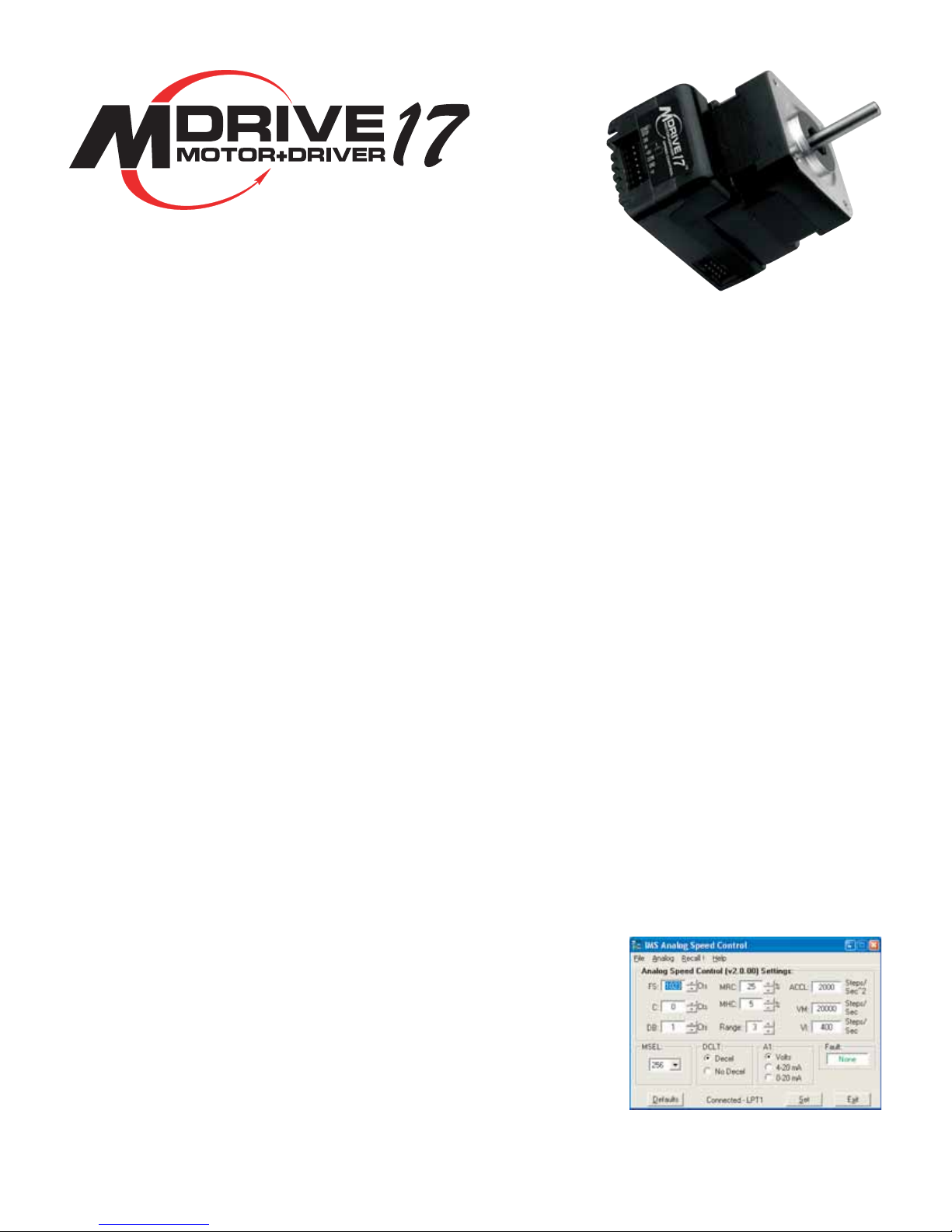
The MDrive17 Speed Control offers
the system designer low cost, intelligent velocity control integrated with a
NEMA 17 high torque stepping motor
and a +12 to +48 volt microstepping
driver.
The MDrive17 Speed Control features a digital oscillator for accurate velocity control with an output
frequency of up to 100 kilohertz.
Output frequency will vary with the
signal applied to the speed control
input. Speed can be adjusted by 1525kHz PWM, 0-20mA, 4-20mA or
0 to +5 volts.
There are two basic modes of operation: bidirectional and unidirectional.
By moving the center point, both
speed and direction are controlled
by the IMS Analog Speed Control GUI.
By setting the center point to zero or
the lower end of the potentiometer,
only velocity is controlled by the speed
control input; direction is controlled
by a separate digital input.
The MDrive17 Speed Control has 12
setup parameters, confi gured using
the supplied IMS Analog Speed Control GUI. The setup parameters enable the user to confi gure all MDrive
operational parameters which are
stored in nonvolatile memory.
The versatile, compact MDrive17
Speed Control is available in multiple
confi gurations to fi t various system
needs. These options include a single
shaft rotary motor , a dual shaft rotary
motor available with optical encoder
or control knob, a planetary gearbox, or a long life Acme screw linear
actuator. The rotary MDrive17 is
available in single, double and triple
stack sizes: 13, 15 & 19. Interface
connections are accomplished using either a 7 position pluggable
terminal strip or 12.0” (30.5cm)
fl ying leads.
CONFIGURING
The IMS Analog Speed Control is
a required software GUI for quick
and easy parameter setup of the
MDrive17 Speed Con trol from a
computer par al lel/SPI port. GUI
access is via the IMS SPI In ter face in clud ed on the CD shipped
with the product, or down load at
www.imshome.com. An optional
Parameter Setup Cable is available
for ease of connecting and confi guring the MDrive.
IMS Analog Speed Control features:
• Easy installation.
• Automatic detection of MDrive
version and communication
confi guration.
• Will not set out-of-range values.
• Tool-tips display valid range
setting for each option.
• Single screen interface
Confi guring the MDrive Speed Control
is simplifi ed with the IMS Analog Speed
Control's single screen interface.
MDrive17 Speed Control Datasheet REV121704 1
(below)
.

MDRIVE17 SPEED CONTROL SPECIFICATIONS
GENERAL SPEC I FI CA TIONS
Speed Control Input ................................... 15 to 25kHz PWM, 0 to 20mA, 4 to 20mA or 0 to +5 VDC
A/D Resolution.................................................................................................................... 10 bit
Speed Control Potentiometer Resistance.................................................................................. 10 kΩ
Input Voltage (+V) Range*........................................................................................+12 to +48 VDC
Stop/Start, Direction (Low Lev el Input)........................................................................ 0 to +1.5 VDC
Stop/Start, Direction (High Lev el Input) ...................................................................+3.0 to +5.0 VDC
Input Pull-up Re sis tance (to +5 VDC) Stop/Start, Di rec tion ......................................................4.99 kΩ
Heat Sink Temperature (Max) ..................................................................................................85° C
Motor Temperature (Max).....................................................................................................100° C
*Power supply current requirements = 2A (maximum) per MDrive17. Actual power supply current will depend on voltage and load.
PARAMETERS
SETUP PARAMETERS
NAME FUNCTION RANGE UNITS DEFAULT
ACCL Accel/Decel 2000 to 65000 steps/sec
C Joystick Center 0 to 1022 counts 0
DB Deadband 0 to 255 counts 1
DCLT Decel Type Decel at ACCL Rate/No Decel -- Decel
A1 Input Mode Volts/4-20mA/0-20mA -- Volts
FS Full Scale 1 to 1023 counts 1023
MHC Motor Hold Current 0 to 100 percent 5
MRC Motor Run Current 1 to 100 percent 25
MSEL Microstep Resolution 2, 4, 5, 8, 10, 16, 25, 32, 50, 64, 125, 128, 250, 256 µsteps per step 256
RANGE VI/VM Range 1 to 8 -- 3
VI Initial Velocity 1 to 100000 steps/sec 400
VM Maximum Velocity 1 to 100000 steps/sec 20000
All parameters are set using the supplied IMS Analog Speed Control GUI.
An optional Parameter Setup Cable is rec om mend ed with fi rst orders.
2
2000
PIN/WIRE ASSIGNMENTS
CONNECTOR P1 – Pluggable Terminal Strip or Flying Leads
PIN FLYING LEADS FUNCTION
1 Violet STOP / START INPUT
2 Blue DIRECTION INPUT
3 Green SPEED CONTROL INPUT (0-5V (10K POT)/PWM/4-20mA/0-20mA)
4 Yellow +5 VDC OUTPUT (10K POT)
5 Gray LOGIC GROUND (10K POT)
6 Black POWER GROUND
7 Red
ENCODER PIN ASSIGNMENTS
ENCODER – Single-End ENCODER – Differential
PIN FUNCTION PIN FUNCTION PIN FUNCTION
1 GROUND 1 NO CONNECT 6 CHANNEL A +
2 INDEX 2 +5 VDC INPUT 7 CHANNEL B –
3 CHANNEL A 3 GROUND 8 CHANNEL B +
4 +5 VDC INPUT 4 NO CONNECT 9 INDEX –
5 CHANNEL B 5 CHANNEL A – 10 INDEX +
Optional Encoder Cables available.
NOTE: For recommended mating connector information, refer to the product's Quick Reference at www.imshome.com/quick.html
+V (+12 TO +48 VDC)
CONNECTOR P2 (SPI) – 10 Pin Pin-Header
PIN FUNCTION
4 CHIP SELECT
5 GROUND
6 +5 VDC OUTPUT
7 MASTER OUT - SLAVE IN
8 CLOCK
10 MASTER IN - SLAVE OUT
Omitted numbers are NO CONNECT
MDrive17 Speed Control Datasheet REV121704 2
MDRIVE17 MOTOR SPECIFICATIONS
MD1713 Single Stack
Holding Torque ...................32 oz-in / 22.6 N-cm
Detent Torque.................1.66 oz-in / 1.17 N-cm
Rotor Inertia
....0.00053
oz-in-sec2 / 0.038
kg-cm
Weight (Motor+Driver)..............9.8 oz / 277.8 g
MD1715 Double Stack
Holding Torque ................60.0 oz-in / 42.4 N-cm
Detent Torque.................2.08 oz-in / 1.47 N-cm
Rotor Inertia
....0.00080
oz-in-sec2 / 0.057
kg-cm
Weight (Motor+Driver)............10.5 oz / 297.7 g
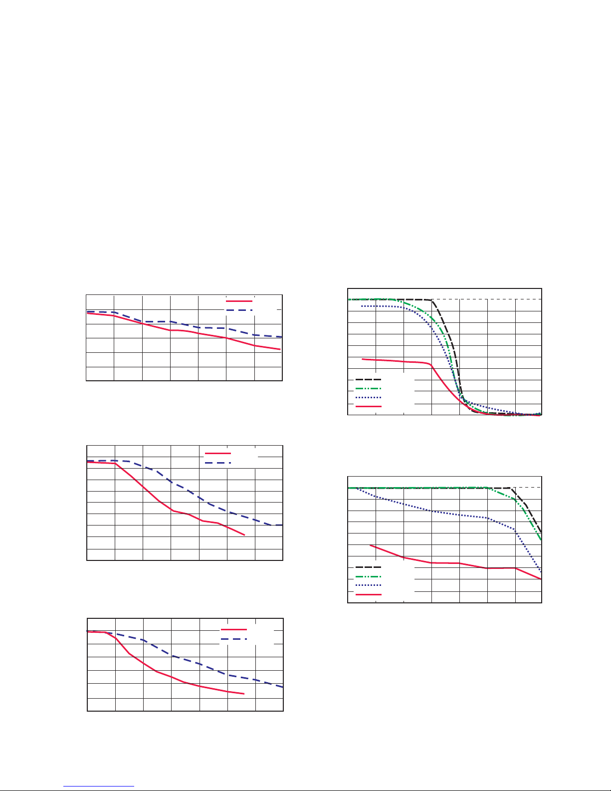
TORQUE-SPEED CURVES
Rotary Motor
MD1713 Single Stack
25
20
15
10
Torque in Oz-In
5
0
1000
500
2000
3000 4000
Speed in Full Steps per Second
MD1715 Double Stack
5000 6000 7000
24 VDC
45 VDC
18
14
11
7
4
MD1719 Triple Stack
Holding Torque ................74.9 oz-in / 52.9 N-cm
Detent Torque.................3.47 oz-in / 2.45 N-cm
2
Rotor Inertia
....0.00116
oz-in-sec2 / 0.082
Weight (Motor+Driver)............15.1 oz / 428.1 g
MD1713 Linear Actuator
Maximum Thrust ........................50 lbs / 222 N
Maximum Screw Defl ection .......................... ± 1°
2
Backlash .........................0.005 in / 0.127 mm
Weight (without screw)........... 10.4 oz / 294.8 g
FORCE-SPEED CURVES
Linear Actuator
24 VDC
Torque in N-cm
50
45
40
35
30
25
20
Force in lbs
15
10
5
0
1000
0
Load Limit 50lbs / 222N
Screw D
Screw C
Screw B
Screw A
2000
3000 4000
Speed in Full Steps per Second
5000 6000 7000
kg-cm
222
200
177
155
133
111
88
66
44
22
2
Force in N
45
40
35
30
25
20
15
Torque in Oz-In
10
5
0
1000
500
2000
3000 4000
Speed in Full Steps per Second
MD1719 Triple Stack
60
50
40
30
20
Torque in Oz-In
10
0
1000
500
2000
3000 4000
Speed in Full Steps per Second
24 VDC
45 VDC
5000 6000 7000
24 VDC
45 VDC
5000 6000 7000
28
25
Torque in N-cm
21
18
14
11
7
4
42
Torque in N-cm
35
28
21
14
7
45 VDC
50
45
40
35
30
25
20
Force in lbs
15
10
5
0
0
1000
Load Limit 50lbs / 222N
Screw D
Screw C
Screw B
Screw A
2000
3000 4000
Speed in Full Steps per Second
5000 6000 7000
222
200
177
155
133
111
88
66
44
22
Force in N
MDrive17 Speed Control Datasheet REV121704 3
MDRIVE17 WITH PLANETARY GEARBOX
The MDrive17 is available with a Planetary Gearbox
option developed to increase torque at lower speeds,
enable better inertia matching and produce fi ner
positional resolutions. These effi cient, low maintenance Planetary Gearbox come fully assembled with
the MDrive and are offered in a large number of
reduction ratios in 1-, 2- and 3-stage confi gurations.
An optional NEMA Flange allows mounting the Planetary Gearbox to the load using a standard NEMA
bolt circle. Planetary Gearbox may be combined with
other MDrive17 options, however are unavailable on
Linear Actuator versions.
Parameters 1-Stage 2-Stage 3-Stage
Permitted Output Torque (oz-in/Nm)...........................425/3.0.............1062/7.5 ........ 2124/15.0
Gearbox Effi ciency.......................................................0.80 ....................0.75 ................. 0.70
Maximum Backlash (degree)........................................ 0.80°...................0.85°.................0.90°
Ouput Side with Ball Bearing
Maximum Load, Radial (lb-force/N)............................ 36/160...............52/230...........67.5/300
Maximum Load, Axial (lb-force/N)............................... 11/50................. 18/80..............25/110
Weight - Gearbox Only (oz/g)....................................14.3/406............17.9/508 ......... 21.5/609
Weight - Gearbox & NEMA Flange (oz/g) ...................14.8/420............18.5/525 ......... 22.2/630
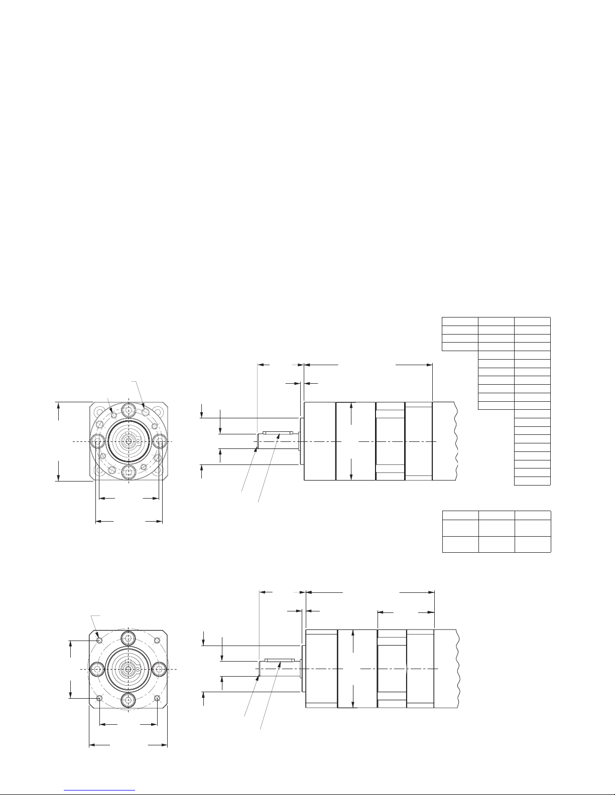
PLANETARY GEARBOX MECHANICAL SPECIFICATIONS
Dimensions in Inches (mm)
Planetary Gearbox for MDrive17
0.984
(25.0)
M4 x 0.394 (10.0) Deep
M3 x 0.394 (10.0) Deep
1.657 SQ.
(42.1 SQ.)
Ø 1.26
(Ø 32.0)
Ø 1.417
(Ø 36.0)
Ø 0.984 +0/-0.002
(Ø 25.0 +0/-0.052)
Ø 0.315 +0/-0.0004
(Ø 8.0 +0/-0.009)
Ctrg. DIN 332 - D M3
Key DIN 6885-A-3x3x16mm
Planetary Gearbox with Optional NEMA Output Flange
k1 ±0.02 (±0.5)
0.08
(2.0)
Ø 1.654
(Ø 42.0)
k1 Gearbox
k2 Gearbox w/
NEMA Flange
Gearbox Ratios (Rounded)
1-Stage 2-Stage 3-Stage
3.70:1 13.73:1 50.89:1
5.18:1 15.88:1 58.85:1
6.75:1 18.36:1 68.06:1
MDRIVE17
Gearbox Lengths
1-Stage 2-Stage 3-Stage
2.736
(69.5)
2.858
(72.6)
19.20:1 71.16:1
22.20:1 78.71:1
25.01:1 92.70:1
26.85:1 95.17:1
28.93:1 99.50:1
34.97:1 107.20:1
45.56:1 115.07:1
3.248
(82.5)
3.37
(85.6)
123.97:1
129.62:1
139.13:1
149.90:1
168.84:1
181.24:1
195.26:1
236.09:1
307.54:1
Inches (mm)
3.76
(95.5)
3.882
(98.6)
M3 x 0.276 (7.0) Deep
Ø 0.866 +0/-0.002
1.22
(31.0)
1.22
(31.0)
1.657 SQ.
(42.1 SQ.)
Ctrg. DIN 332 - D M3
Key DIN 6885-A-3x3x16mm
(Ø 22.0 +0/-0.052)
Ø 0.315 +0/-0.0004
(Ø 8.0 +0/-0.009)
0.846
(21.5)
k2 ±0.02 (±0.5)
0.08
(2.0)
Ø 1.654
(Ø 42.0)
1.20
(30.5)
MDRIVE17
MDrive17 Speed Control Datasheet REV121704 4

MDRIVE17 SPEED CONTROL – MECHANICAL SPECIFICATIONS
)
Dimensions in Inches (mm)
Rotary MDrive17: Single Shaft, Control Knob & Encoder Versions
2.16
(54.9)
Interface
Option
P1
(33.8)
0.08
(2.0)
P2
L
MAX
L
MAX2
1.33
MDrive Lengths
Stack Size
1713 2.20 (55.9) 2.92 (74.2)
1715 2.43 (61.7) 3.15 (80.0)
1719 2.75 (69.8) 3.47 (88.1)
Inches (mm)
L
MAX
SINGLE SHAFT
VERSION
CONTROL KNOB or
ENCODER VERSION
0.94 ±0.02
(24.0 ±0.5)
0.59 ±0.02
(15.0 ±0.5)
0.177 ±0.002
(4.5 ±0.05)
Ø 0.1968
(Ø 5.0)
Ø 0.866
(Ø 22.00)
L
MAX2
+0.000
-0.0005
(-0.012)
+0.000
-0.002
(-0.051)
1.67 SQ.
(42.4 SQ.)
Interface Options
12.00
+1.0/-0.0
(304.8)
(+25.4/-0.0)
4X M3x0.5 THREAD
x 0.15 MIN DEEP
1.22 ±0.004 SQ.
(31.0 ±0.1 SQ.)
0.44
(11.2)
L
Options
MAX2
Ø 0.97
(Ø 24.6)
Control Knob
100 - 1000 Line Encoders
Linear Actuator MDrive17
6.00
(152.4)
Option
P1
P2
1.33
(33.8)
(55.6)
2.19
Interface
0.250
(6.35)
2.16
(54.9)
1.20
(30.4)
Differential
Adapter
.
0.08
(2.0)
1.90
(48.3
1.42
(36.1)
#8-32 UNC-2A
Thread to within
0.03 (0.76) of Shoulder
0.25
(6.4)
Flying Leads
1.66 SQ.
(42.2 SQ.)
Pluggable Clamp
Type Terminal Strip
4X M3x0.5 THREAD
x 0.15 MIN DEEP
1.22 ±0.004 SQ.
(31.0 ±0.1 SQ.)
Ø 0.866
(Ø 22.00)
+0.000
-0.002
(-0.051)
MDrive17 Speed Control Datasheet REV121704 5
MDRIVE17 SPEED CONTROL – OPTIONS
Control Knob
The MDrive17 is available with a fac to ry-mount ed rear
control knob for man u al shaft positioning.
Planetary Gearbox
Effi cient, low maintenance Planetary Gearbox are of-
fered assembled with the MDrive17. Details inside.
Encoder
The MDrive17 is available with a factory-mount ed
op ti cal en cod er. Available line counts are 100, 200,
250, 400, 500 or 1000. All en cod ers, except
1000 line, have an in dex mark. Encoders are available in both single-end and dif fer en tial confi gurations.
Order optional Encoder Cables separately:
Single-end Cable (12"/30.5cm) ..... ES-CABLE-2
Differential Cable (36"/91.5cm).....ED-CABLE-2
Linear Actuator
The MDrive17 with long life Acme Screw Linear Actua-
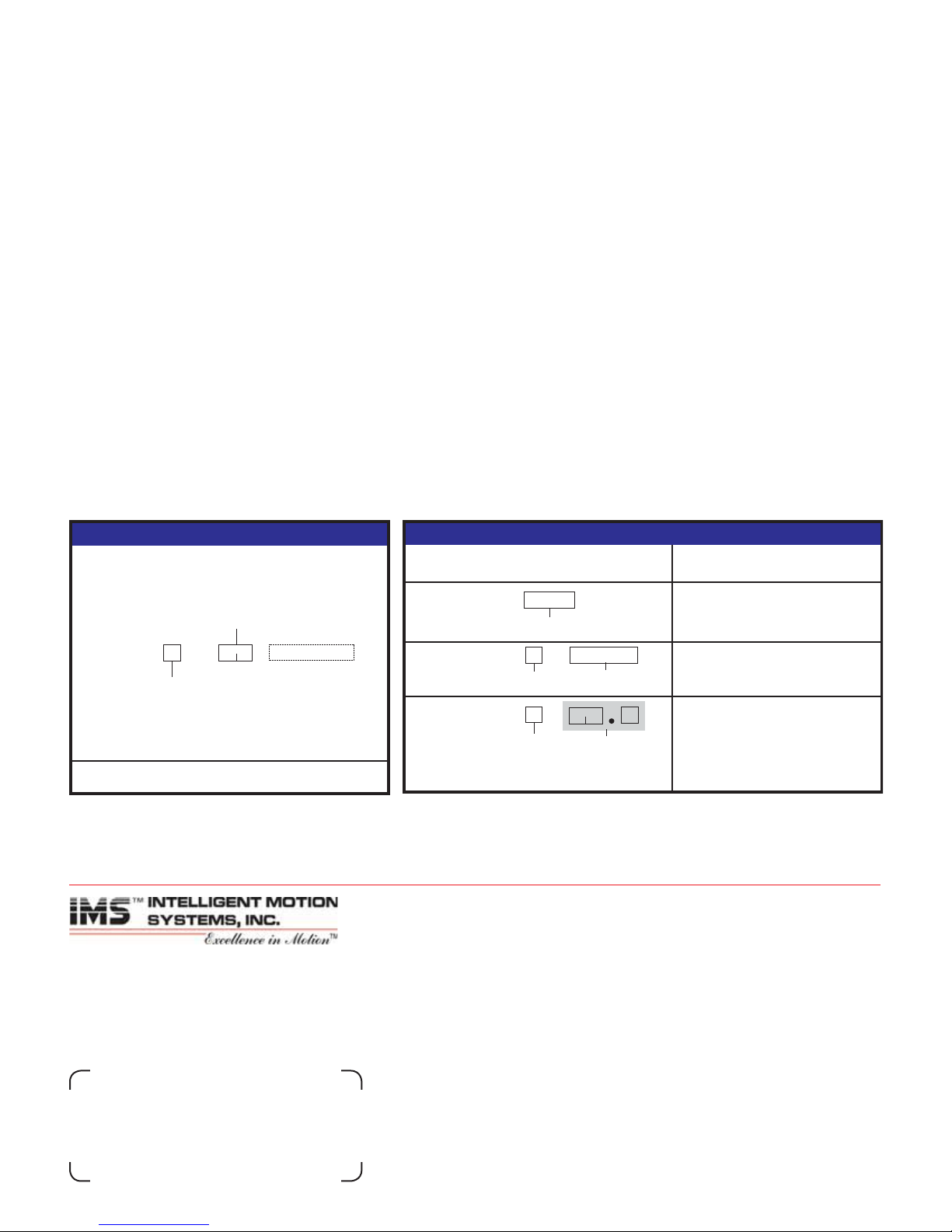
ORDER INFORMATION
MDRIVE17 SPEED CONTROL
Control
Knob
Stack Sizes
†
13 = Single Stack & Linear Actuator
15 = Double Stack
19 = Triple Stack
MDO 17
Interface Options
F = 12” Flying Leads
P = Pluggable Clamp
Type Terminal Strip
Example #1: Part Number MDOP1719 is an MDrive17 Speed
COntrol with Pluggable Interface, NEMA 17 motor, stack size 19.
OPTION
†Linear Actuator Available ONLY in Stack Size 13. (MDOX1713LX)
Planetary
Gearbox
Encoder
Linear
Actuator
Screw Type (Travel/Full Step)
A = 0.00125”
B = 0.000625”
C = 0.0003125”
D = 0.00015625”
tor is avail able with the following trav el/full step:
Screw A ..............0.00125”/full step
Screw B ..............0.000625”/full step
Screw C ..............0.0003125”/full step
Screw D .............. 0.00015625”/full step
Standard screw length is 6.0” (152.4mm) plus the
mounting end thread. Cus tom lengths from 2.0” to
24.0” are available without mounting end thread.
Linear Actuators are Non-Captive style. Contact the
factory regarding Captive Shaft or External styles.
Parameter Setup Cable
A low cost ac ces so ry which eliminates the need for
users to wire com mu ni ca tions. This 6' (1.8m) cable
includes built-in logic level shifting circuitry to ac com mo date the 3.3v por ts on some PCs and plugs in
easily to con nect a stan dard DB-25 PC par al lel/SPI
port to the MDrive's 10 pin pin-header (P2). Order
Cable Part No. MD-CC100-000.
N
G
Gearbox Ratio
Rounded to Nearest Whole Number
E
S = Single End
D = Differential
†
L
Line Counts: 100, 200,
250, 400, 500, 1000
Custom Screw Length
Range 2.0” to 24.0”
Format XX.X
eg. 08.5 for an 8.5” Screw
(6.0” Screw Length Standard)
OPTIONS
Example #2: MDOP1719N
Adds a Control Knob
to the part shown in example #1.
Example #3: MDOP1719G5
Rounding ratio to the nearest whole number,
the above adds a Planetary Gearbox with
5.18:1 ratio to the part shown in example #1.
Add -F if optional NEMA Flange is desired.
Example #4: MDOP1719ED500
Adds a 500 line count Differential Encoder
to the part shown in example #1.
Example #5: MDOP1713LC10.5
MDrive17 Speed Control Linear Actuator
with a 0.0003125”/Full Step Acme
Screw custom cut to 10.5”.
MAY NOT be combined with other options.
Note: MDrive17 Linear Actuator
Available ONLY in Stack Size 13
P.O. Box 457, 370 N. Main Street
Marlborough, CT 06447 U.S.A.
Phone: 860/295-6102
Fax: 860/295-6107
E-mail: info@imshome.com
Home Page: www.imshome.com
Distributed By:
TECHNICAL SUPPORT
Eastern U.S.
Phone: 860/295-6102
Fax: 860/295-6107
E-mail: etech@imshome.com
Western U.S.
Phone: 760/966-3162
Fax: 760/966-3165
E-mail: wtech@imshome.com
IMS MOTORS DIVISION
105 Copperwood Way, Suite H
Oceanside, CA 92054
Phone: 760/966-3162
Fax: 760/966-3165
E-mail: motors@imshome.com
Product information covered by IMS Product Disclaimer available at www.imshome.com.
Visit the IMS web site for the most up-to-date product information.
© 2002, 2004 Intelligent Motion Systems, Inc. All Rights Reserved. REV111104
IMS EUROPE
Hahnstrasse 10, VS-Schwenningen
Germany D-78054
Phone: +49/7720/94138-0
Fax: +49/7720/94138-2
E-mail: info@imseuropehome.com
European Sales Management
4 Quai Des Etroits
69005 Lyon, France
Phone: +33/4 7256 5113
Fax: +33/4 7838 1537
E-mail: bmartinez@imshome.com
German Sales/Technical Support
Phone: +49/35205/4587-8
Fax: +49/35205/4587-9
E-mail: hruhland@imshome.com
GmbH
 Loading...