

pag 1 of 201
SERVICE AND INSTALLATION MANUAL
M189_EN:
Draft version_0.1 del 01/07/15

SERVICE AND
INSTALLATION
MANUAL
Via Sagittario 5 - 40037
Pontecchio Marconi (Bo)
Tel. ++39 051 846851
Fax. ++39 051 846856
www.imsitaly.com
pag 2 of 201
M189_EN:
Draft version_0.1 del 01/07/15

SERVICE AND
INSTALLATION
MANUAL
Via Sagittario 5 - 40037
Pontecchio Marconi (Bo)
Tel. ++39 051 846851
Fax. ++39 051 846856
www.imsitaly.com
pag 3 of 201
Index:
1. Safety.................................................................................................... 10
1.1. Convensions ..................................................................................................... 10
1.2. Safety systems .................................................................................................. 15
1.3. Resuming operation after an emergency stop .................................................. 17
1.4. General Safety precautions............................................................................... 19
1.5. Protection and safety regulation ........................................................................ 19
1.6. Warnings and precaustions............................................................................... 19
1.7. General safety warning ..................................................................................... 21
1.8. Radiation protection warnings ........................................................................... 21
1.9. Electrical safety device ..................................................................................... 21
1.10. Exsplosion hazard ............................................................................................. 22
1.11. Risk associated witj cleaning the device ........................................................... 22
1.12. X-ray emission safety ........................................................................................ 22
1.13. Regulations, laws and normative reference ...................................................... 22
2. General Information............................................................................. 23
2.1. Labels ............................................................................................................... 23
2.2. Technical data ................................................................................................... 31
3. Panoramic view of the system ............................................................ 60
3.1. Description of the system .................................................................................. 60
4. Transport and moving ......................................................................... 65
4.1. Contents of the delivery .................................................................................... 65
4.2. Packing characteristic ................................ ....................................................... 65
4.3. Components inside the gantry packing ............................................................. 66
4.4. Components inside the AWS packing ............................................................... 67
4.5. Lifting and moving of packing ............................................................................ 68
4.6. Storage of packed equipment ........................................................................... 69
4.7. Removing the gantry from the pack .................................................................. 71
4.8. Removing the AWS from the pack .................................................................... 72
4.9. Disposal of the packing ..................................................................................... 72
M189_EN:
Draft version_0.1 del 01/07/15

SERVICE AND
INSTALLATION
MANUAL
Via Sagittario 5 - 40037
Pontecchio Marconi (Bo)
Tel. ++39 051 846851
Fax. ++39 051 846856
www.imsitaly.com
pag 4 of 201
4.10. Instructions for the handling, storing and packing of digital detector ................. 73
5. Installation ........................................................................................... 77
5.1. Ambient requirements conditions ...................................................................... 77
5.2. Preliminary radiology room inspection .............................................................. 78
5.3. Preliminary mechanical clamping inspection..................................................... 78
5.4. Installation procedure ........................................................................................ 79
6. Preliminary operating check ............................................................... 87
6.1. Checks before using the unit............................................................................. 87
6.2. Initial start-up .................................................................................................... 88
6.3. Troubleshooting before initial start-up ............................................................... 90
6.4. Quality checks before clinical application .......................................................... 92
6.5. Connection to the DICOM ntework ................................................................... 92
6.6. Operator instructions ......................................................................................... 93
7. Method of use ...................................................................................... 94
7.1. Equipment ......................................................................................................... 94
7.2. Acquisizione Work Station .............................................................................. 109
7.3. System Messages ........................................................................................... 114
7.4. Patient Registration ......................................................................................... 115
7.5. Exposure data setting ..................................................................................... 117
7.6. Performing the exposure ................................................................................. 118
7.7. Printing the exam images ............................................................................... 122
7.8. Concluding the exam ...................................................................................... 122
7.9. Manually sending images to other DICOM workstation .................................. 122
8. Image quality assessment ................................................................ 124
8.1. AEC Test for Installation ................................................................................. 125
8.2. Dose Calibration check ................................................................................... 133
8.3. Image Honogeneity and defective element evaluation .................................... 134
9. Components diagnosis ..................................................................... 140
9.1. Geometry of acquisition setting ................................................................ ....... 140
9.2. Detector .......................................................................................................... 141
M189_EN:
Draft version_0.1 del 01/07/15

SERVICE AND
INSTALLATION
MANUAL
Via Sagittario 5 - 40037
Pontecchio Marconi (Bo)
Tel. ++39 051 846851
Fax. ++39 051 846856
www.imsitaly.com
pag 5 of 201
9.1. X-ray tube ....................................................................................................... 151
10. Electronic boards .......................................................................... 161
10.1. Electronic boards topographic diagram ........................................................... 161
10.2. I008 – Collimator board ................................................................................... 162
10.3. I009 Compressor board .................................................................................. 163
10.4. I009PB Compressor Piggy Back board ........................................................... 164
10.5. I010 Detector .................................................................................................. 165
10.6. I011 Biopsy board ........................................................................................... 166
10.7. I011AC Biopsy cabling switching .................................................................... 167
10.8. I012 Gantry boards ......................................................................................... 167
10.9. I013 SELEMA actuation .................................................................................. 168
10.10. I014 Gantry keyboard ..................................................................................... 168
10.11. I015 Tube keyboard ........................................................................................ 168
10.12. I017 Wireless foot pedals power board ........................................................... 169
10.13. I020 Power switching board ............................................................................ 169
10.14. I021 Operator control table command board .................................................. 170
10.15. I022 Operator control table Cabling switching board ...................................... 170
11. Maintenance .................................................................................. 171
11.1. Warnings on routine maintenance .................................................................. 171
11.2. Cleaning .......................................................................................................... 172
11.3. Preventive maintenance program ................................................................... 173
11.4. Disposal and scrapping of the obsolete equipment ......................................... 175
12. Breakdowns and diagnosis .......................................................... 176
12.1. Introduction ..................................................................................................... 176
12.2. Alarms management ....................................................................................... 177
12.3. List of alarms ................................................................................................... 180
13. Interventions on the equipment ................................................... 181
13.1. Introduction ..................................................................................................... 181
M189_EN:
Draft version_0.1 del 01/07/15

SERVICE AND
INSTALLATION
MANUAL
Via Sagittario 5 - 40037
Pontecchio Marconi (Bo)
Tel. ++39 051 846851
Fax. ++39 051 846856
www.imsitaly.com
pag 6 of 201
IMS S.r.l. All rights reserved.
No part of this manual can be reproduced, transmitted, transcribed or filed in a retrieval system or
translated into other languages in any form with any means without written consent from IMS S.r.l.
The buyer may reproduce copies for personal use.
This manual is considered an integral part of the equipment. It must be immediately replaced with
another copy if any part of it is ruined or illegible.
Before performing any type of operation on the equipment, IMS S.r.l. requires that anyone of any
title involved in using the equipment carefully read the entire contents of this manual, paying
special attention to the important warnings.
IMS S.r.l. may not be held responsible for the improper use of the equipment, and for damages
caused by unreasonable operations.
The equipment must only be used to meet the needs for which it was expressly designed. Any
other improper use is considered dangerous.
IMS S.r.l. is considered responsible for the equipment only if it is in its original configuration
determined in the design phase. Any modifications to the structure and the equipment’s operating
cycle must by expressly authorized by the IMS S.r.l. Technical Department.
IMS S.r.l. recommends that only original replacement parts be used and therefore cannot be held
responsible for any damages caused after the use of non-original replacement parts.
IMS S.r.l. reserves the right to modify the design and to make marketable improvements without
forewarning customers who already possess similar models.
IMS S.r.l. is considered responsible for the descriptions written in Italian. The translations cannot
be fully verified, therefore if the buyer finds a discrepancy in the text, this person should refer to the
Italian version and possibly contact our Technical Documentation Office, which will make any
necessary changes.
IMS S.r.l. would like to thank you for choosing one of our machines and we are sure that it will fully
satisfy your needs for a long period of time.
IMSS.r.l.
Internazionale Medico Scientifica
Via Sagittario 5 - 40037 Pontecchio Marconi - Bologna - Italy
Tel ++39 051 846851 - Fax ++39 051 846856
e-mail: Export Dept.: imscomm@imsitaly.com
Tecnical Dept.: imstech@imsitaly.com
http://www.imsitaly.com
M189_EN:
Draft version_0.1 del 01/07/15
SERVICE AND
INSTALLATION
MANUAL
Via Sagittario 5 - 40037
Pontecchio Marconi (Bo)
Tel. ++39 051 846851
Fax. ++39 051 846856
www.imsitaly.com
pag 7 of 201
IEC 60601-1
Class
I
Type
B
Medical Device Directive 93/42/CE
Class
II B
DOCUMENT N°:
M189_EN
REVISON:
0.1
DATA:
01/07/15
N° REV.
DATE
Purpose of the revisions
Modified PAGES
Modified SECTION
01
01/07/15
Initial release
Intended use
The Giotto Class and its accessories are designed and built mammography examination for the
screening in modality of Full-Field Digital mammography (FFDM) and for diagnosis in modality of
Digital-Breast Tomosynthesis (DBT) for breast cancer detection and cannot be used for other
examinations or for purposes other than those specified by the Manufacturer. Its practical use is
therefore exclusively limited to personnel with medical training.
Using the accessory devices Smart Finder and Flexi table the system is able to perform
stereotactic biopsy examination with the optional possibility to perform the examination with patient
in prone position.
CE: 1936
CLASSIFICATION AND COMPLIANCE
REVISIONS OF THE MANUAL
Please comply with that reported in Section 1 - “Safety”.
Carefully read Section 1 - “Safety” before operating the equipment.
MANUFACTURER’S WARNINGS
This product has the CE marking in conformance with the provisions outlined in Annex II of
93/42/EEC of 14 June 1993 concerning medical devices.
The CE marking is only valid for technical medical products/medical devices put on the market
during the validity of the EC directive indicated above.
If modifications are made to the product without our authorization, the declaration will no longer be
valid.
The original version of this manual was drafted in Italian.
M189_EN:
Draft version_0.1 del 01/07/15

SERVICE AND
INSTALLATION
MANUAL
Via Sagittario 5 - 40037
Pontecchio Marconi (Bo)
Tel. ++39 051 846851
Fax. ++39 051 846856
www.imsitaly.com
pag 8 of 201
DO YOU HAVE ANYTHING TO REPORT WITH REGARD TO THIS MANUAL?
Your opinion means a great deal to us!
We strive to constantly improve the documentation of our equipment. To help do this, we give you
the opportunity to directly inform us of any need, suggestion or comment relating to this instruction
manual.
Use the following number to send notices via FAX:
• +39 051 846851.
If you prefer to communicate via e-mail, please use this address:
• imstech@imsitaly.com
In this case, please indicate the complete print reference code reported on the third page.
Thank you for your collaboration.
What I would like to report:
______________________________________________________________________________
______________________________________________________________________________
______________________________________________________________________________
______________________________________________________________________________
______________________________________________________________________________
______________________________________________________________________________
Non-mandatory data
Name _________________________________________________________________________
Hospetal_______________________________________________________________________
City/Country ____________________________________________________________________
E-mail _________________________________________________________________________
Tel./Fax _______________________________________________________________________
Number of Fax pages ____________________________________________________________
M189_EN:
Draft version_0.1 del 01/07/15

SERVICE AND
INSTALLATION
MANUAL
Via Sagittario 5 - 40037
Pontecchio Marconi (Bo)
Tel. ++39 051 846851
Fax. ++39 051 846856
www.imsitaly.com
pag 9 of 201
M189_EN:Safety
Draft version_0.1 del 01/07/15

SERVICE AND
INSTALLATION
MANUAL
Via Sagittario 5 - 40037
Pontecchio Marconi (Bo)
Tel. ++39 051 846851
Fax. ++39 051 846856
www.imsitaly.com
pag 10 of 201
Sections
This manual is made up of various sections, the titles of which are reported in the
heading.
Paragraphs
Every section can have one or more paragraphs, the title of which is reported in
the text below the heading.
Page
numbers
The page footer shows the progressive page numbers.
1. Safety
1.1. Conventions
In order for the manual to be read quickly and rationally, symbols have been employed for
highlighting practical advice, simple information or situations in which great care must be taken.
Said symbols can be found alongside a section of text (and therefore refer only to that text),
alongside a figure (and refer to the subject illustrated in the figure and to the relative text) or at the
top of the page (in which case they refer to all the subjects treated on that page).
Pay maximum attention to the meaning of the symbols: their aim is not to have to repeat technical
concepts or safety warnings and therefore should be considered as proper “reminders”.
Thus, refer to the list of symbols whenever doubts arise as to their meaning. The symbols shown
in the following pages are not found on the device or its accessory parts; they are only present
in this manual. The series of the manuals supplied with the device usually contains some
documents not made up by I.M.S. S.r.l., which could use edition symbols that are graphically
different from the ones shown in this publication. Therefore, it is advisable to consult all the
documents supplied in order to “store” all the subjects for which the symbols themselves have
been used.
It is important not to confuse the edition symbols on the device with the “safety” plates, which are
applied in predetermined points on the device, auxiliary units, etc...
1.1.1. Structure of the manual
M189_EN:Safety
Draft version_0.1 del 01/07/15
SERVICE AND
INSTALLATION
MANUAL
Via Sagittario 5 - 40037
Pontecchio Marconi (Bo)
Tel. ++39 051 846851
Fax. ++39 051 846856
www.imsitaly.com
pag 11 of 201
Instruction
Fornisce istruzioni sul corretto utilizzo dell’apparecchiatura.
Questo testo è preceduto da un rombo.
LIST OF
EXPLANATORY
TEXT
–
This text is preceded by a dot.
Divides an instruction or a list into various sub-parts.
This text is preceded by a dash.
REFERENCE
Refers to more detailed instructions reported in another page
of the manual or another document.
This text is marked by an arrow.
NOTE
This is used in two ways:
highlights important safety information, without which there is an
immediate risk
contains a summary of the main information regarding a subject matter
This text is highlighted inside a grey box.
Menu
The names of the menus are in bold type.
WARNING
Firstly, the source of the danger is indicated.
The possible consequences are then reported.
Finally, you are informed on how to avoid the danger.
LIFT ONLY FROM THE TOP
Operations that require the use of qualified personnel and specific equipment, and the
respect of the conditions stated by the Manufacturer and current regulations.
1.1.2. Text formatting
This manual contains certain text formats that are helpful in understanding the function of the text
more quickly.
The following characters were used:
1.1.3. Warning, caustions and information
The icons in a box give information .
The symbols in a triangle are DANGER/WARNING symbols.
The symbols in a circle represent an OBLIGATION/PROHIBITION..
1.1.3.1. Warning
Warnings indicate the possible presence of risks for the health and safety of patients, operators
and third parties.
M189_EN:Safety
Draft version_0.1 del 01/07/15
SERVICE AND
INSTALLATION
MANUAL
Via Sagittario 5 - 40037
Pontecchio Marconi (Bo)
Tel. ++39 051 846851
Fax. ++39 051 846856
www.imsitaly.com
pag 12 of 201
CAUTION
Firstly, the source of the danger is indicated.
The possible consequences are then reported.
Finally, you are informed on how to eliminate the danger.
NO!
Operations to be absolutely avoided.
INFORMATION
Il relativo testo è scritto in corsivo dentro il box grigio
EQUIPMENT TURNED OFF
With electrical power supplies isolated
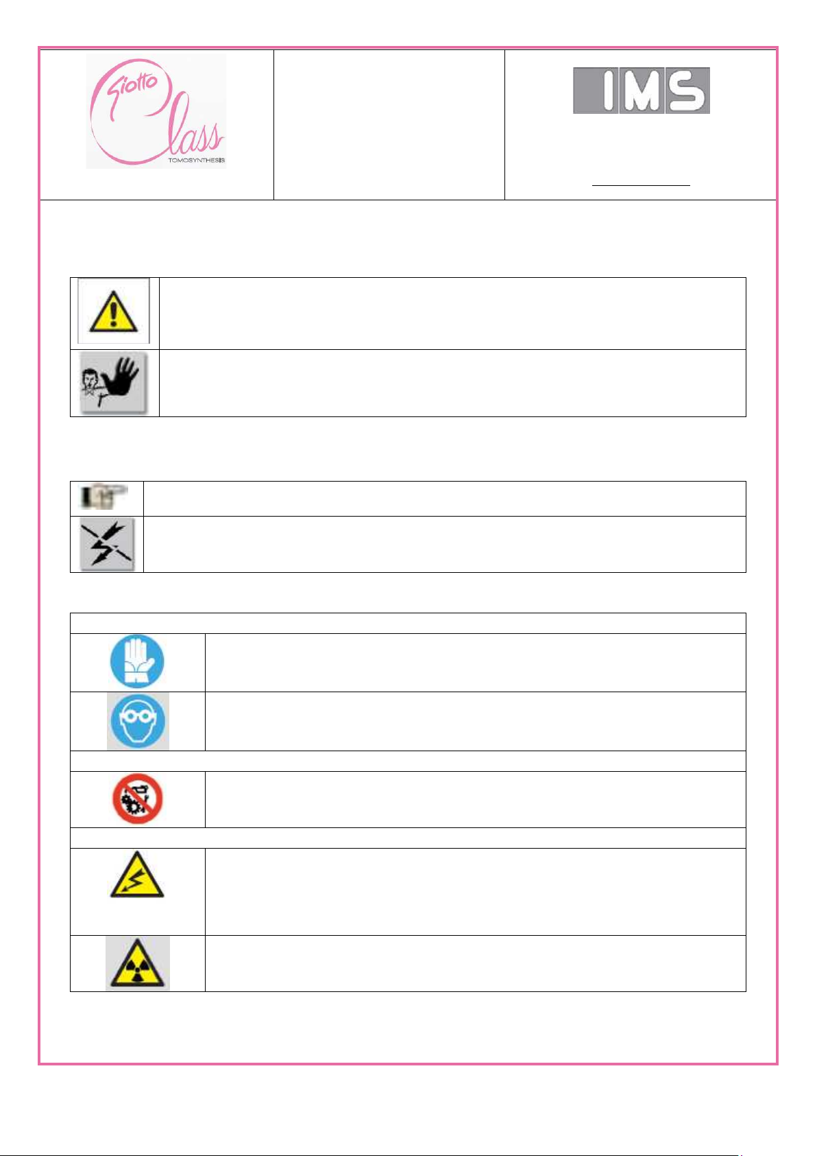
OBLIGATION symbols
Use PROTECTIVE GLOVES
This symbol indicates that the maintenance engineer must wear protection
gloves to avoid injuries.
Use PROTECTIVE GLASSES
This symbol indicates that the maintenance engineer must wear protective
glasses to avoid injuries
PROHIBITION symbols
No MAINTENANCE/REPAIRS ON MOVING MEMBERS
It is forbidden to repair, adjust, clean or lubricate moving members of the
machine
HAZARD/CAUTION symbols
CAUTION: ELECTRIC SHOCK HAZARD
It indicates the presence of electric devices and powered components and
warns the operator against electric shock hazards.
The electric maintenance engineer is the only operator that is qualified to carry
out adjustments or maintenance of the electric cabinets and junction boxes
CAUTION!
It indicates the presence of ionizing radiation.
1.1.1.1. Caution
This indication reports that an incorrect command could cause minor injuries or damage to the
equipment.
1.1.1.1. Information
This indication provides further explanations about an issue.
1.1.1.1. Safety symbols
M189_EN:Safety
Draft version_0.1 del 01/07/15
SERVICE AND
INSTALLATION
MANUAL
Via Sagittario 5 - 40037
Pontecchio Marconi (Bo)
Tel. ++39 051 846851
Fax. ++39 051 846856
www.imsitaly.com
pag 13 of 201
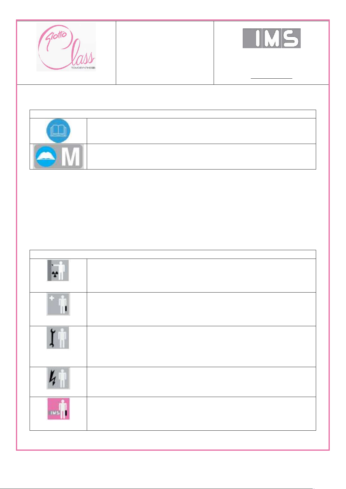
SYMBOLS FOR THE MANUALS
THIS OPERATOR MANUAL
Descriptions inherent to this manual.
SUBCONTRACTING MANUALS
Consult the attached documents relating to subcontracting.
OPERATORS
Radiological technician: the person in charge of preparing the equipment,
positioning the patient and performing the mammography examination,
according to the indications given by the doctor.
Doctor: the person who visits the patient in advance in order to decide the
examination method. This person observes the plates taken by the radiological
technician. He/she carries out the invasive operations (biopsy) on the patient.
Mechanical maintenance personnel: qualified technician able to intervene
on the mechanical parts of the equipment to perform any necessary
maintenance interventions and repairs. This person is not qualified to work
on live-electrical circuits.
Electrician: qualified technician able to carry out any necessary interventions
of an electrical or electronic nature. This person is qualified to work on live-
electrical circuits.
Manufacturer’s technician: qualified personnel provided by the Manufacturer
to perform complex operations under particular situations or when agreed
upon with the Buyer
1.1.1.1. Manuals symbols
1.1.1.1. Qualification of the personnel in charge with operation of the
equipment
The operators that have access to the equipment must be specifically qualified, trained and
responsible for the tasks they are in charge with.
A description of the professional qualifications of the operators and maintenance personnel is
given below. Each profile is graphically described by an icon.
M189_EN:Safety
Draft version_0.1 del 01/07/15
SERVICE AND
INSTALLATION
MANUAL
Via Sagittario 5 - 40037
Pontecchio Marconi (Bo)
Tel. ++39 051 846851
Fax. ++39 051 846856
www.imsitaly.com
pag 14 of 201
INFORMATION
In some figures the equipment may be highly equipped or outfitted with optional
accessories.
INFORMATION
A test report shall be filed in I.M.S. S.r.l. archive.
The names and data of all the patients and devices used in this manual as examples are fictitious.
Any similarity or correspondence to the actual names of people or institutions are purely
coincidental.
All the parameters and images reported in this manual are examples. The parameters seen in your
system are determining factors.
1.1.1. Regulations and laws
If there are regulations with legal implications for the installation and/or use of the device, the
installer and user must respect them. The national standards must be respected in every country.
With the exception of that given in this manual, the values can be set based on the national
standards.
This product has the CE marking in conformance with the provisions contained in directive
93/42/EEC of 14 June 1993 concerning medical devices,
Personal data are protected.
Please respect the regulations pertaining to this matter. During the manufacturing phase, the
equipment is checked according to applicable product standards.
The tests to be performed at the equipment installation site are the responsibility of the customer.
M189_EN:Safety
Draft version_0.1 del 01/07/15
SERVICE AND
INSTALLATION
MANUAL
Via Sagittario 5 - 40037
Pontecchio Marconi (Bo)
Tel. ++39 051 846851
Fax. ++39 051 846856
www.imsitaly.com
pag 15 of 201
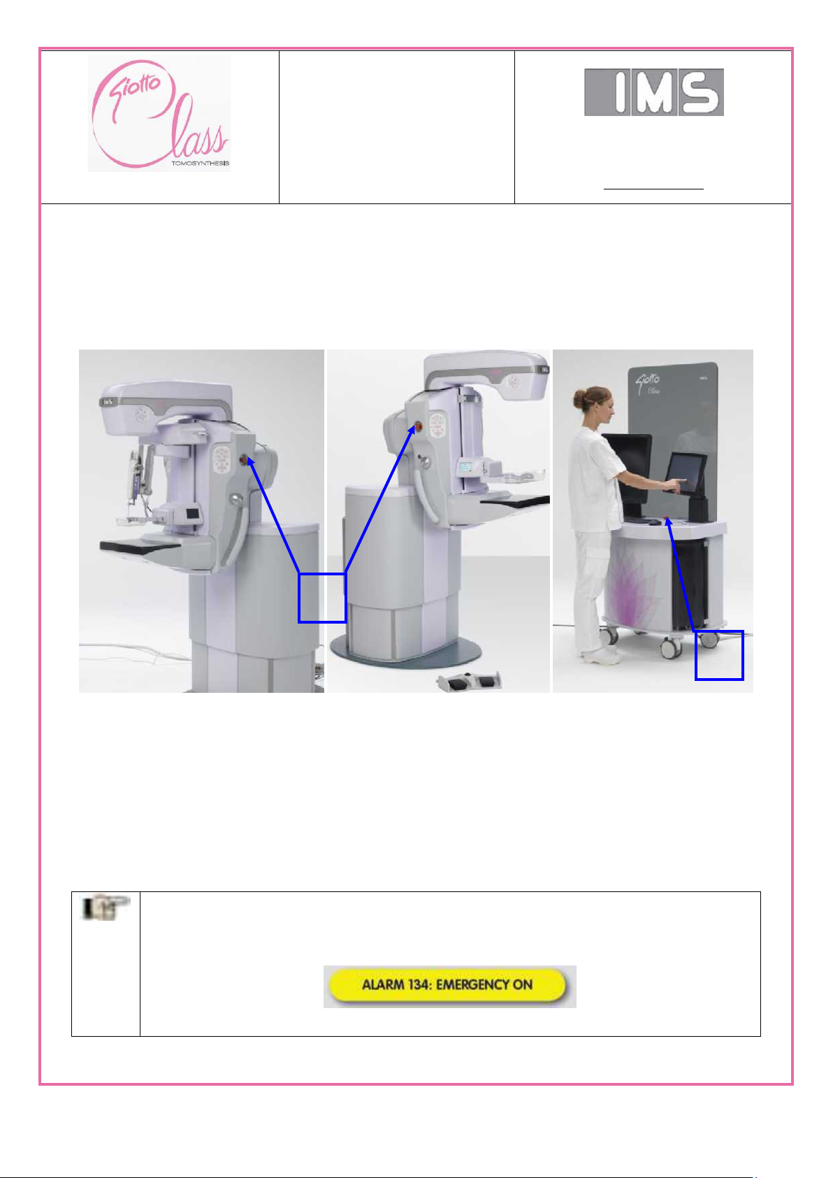
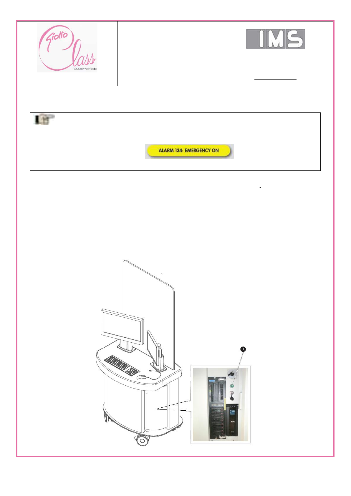
INFORMATION
After pressing one of these three emergency stop buttons, the following message
appears on the touchscreen panel
and an acoustic signal is simultaneously emitted.
1
2
1.2. Safety systems
1.2.1. Emergency stop buttons
Three emergency stop buttons are installed on the equipment described in this manual. If
pressed, they immediately stop all equipment functions.
1) EMERGENCY STOP button located on both sides of the vertical X-ray unit (GANTRY) near two
columns push-button panels.
2) EMERGENCY STOP button located on control table of the acquisition workstation (AWS).
Never use the emergency stop button as a normal stop device to immediately stop all functions of
the equipment, but only in cases of an actual emergency and if malfunctions occur.
After the EMERGENCY STOP button has been activated, keep in mind the following:
M189_EN:Safety
Draft version_0.1 del 01/07/15
SERVICE AND
INSTALLATION
MANUAL
Via Sagittario 5 - 40037
Pontecchio Marconi (Bo)
Tel. ++39 051 846851
Fax. ++39 051 846856
www.imsitaly.com
pag 16 of 201
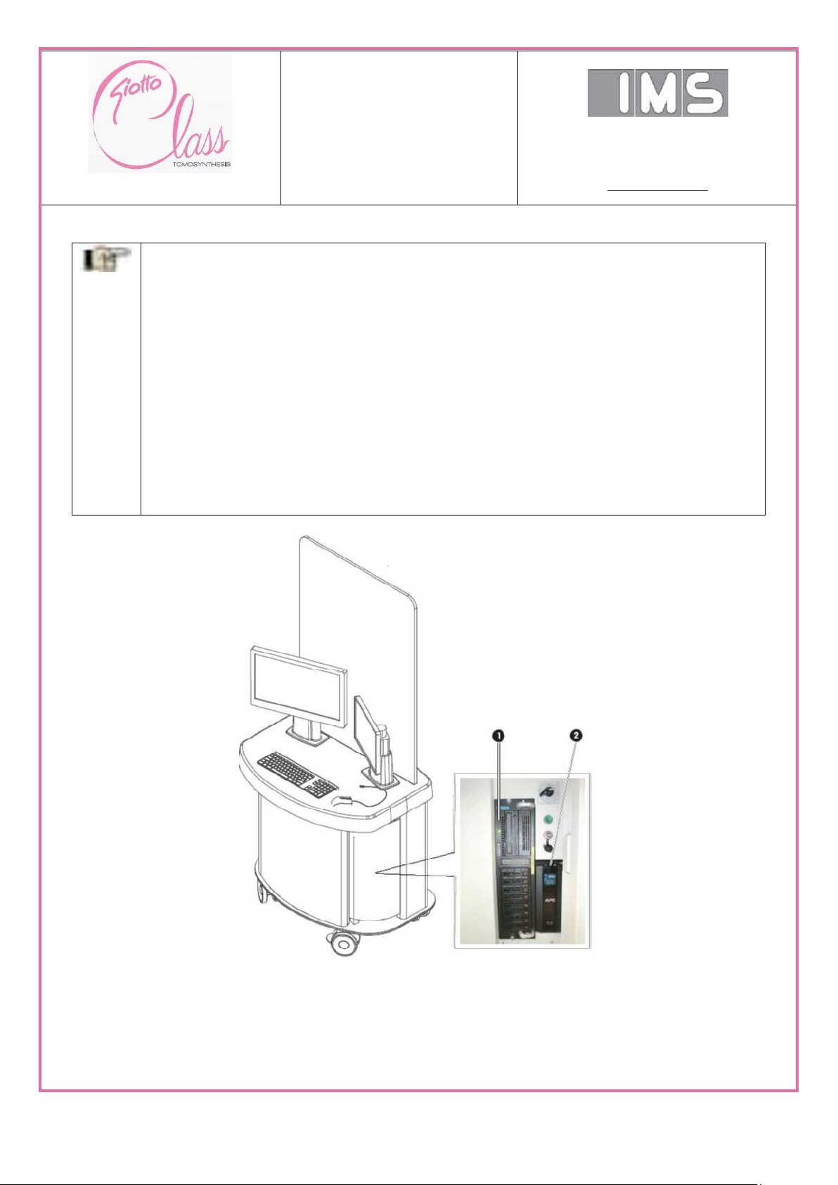
INFORMATION
The emergency stop button does not cut power to the workstation 1. The workstation
is also protected by an uninterruptible power supply UPS 2. The UPS takes power
from the equipment’s circuit; thus turning on “0” position the main switch, the UPS
switches to the batteries and the operator is informed of this operation by an acoustic
signal.
In the case of a power interruption, only the AWS acquisition workstation is powered
by the UPS for a few minutes (depending on the state of the battery). When the
battery of the uninterruptible power supply reaches 20%, the workstation
automatically turns off, following the operating system’s safety sequence.
M189_EN:Safety
Draft version_0.1 del 01/07/15
SERVICE AND
INSTALLATION
MANUAL
Via Sagittario 5 - 40037
Pontecchio Marconi (Bo)
Tel. ++39 051 846851
Fax. ++39 051 846856
www.imsitaly.com
pag 17 of 201
INFORMATION
After pressing one of these three emergency stop buttons, the following message
appears on the touchscreen panel
and an acoustic signal is simultaneously emitted.
1.3. Resuming operation after an emergency stop
Release the pressed emergency stop button by turning it (slightly). The acoustic signal will be
silenced and the alarm message on the touch screen panel will disappear ( see Section 12 -
“Breakdowns and diagnosis”).
To resume operations, press the engage circuits push-button 1 sited on the acquisition
workstation control table switching it to the “OFF” position (LED off). What a few seconds and
then press the engage circuits pushbutton 1 again, switching it to the “ON” position (LED on).
If the cause of the stop has been eliminated, the device will then be operational again.
M189_EN:Safety
Draft version_0.1 del 01/07/15
SERVICE AND
INSTALLATION
MANUAL
Via Sagittario 5 - 40037
Pontecchio Marconi (Bo)
Tel. ++39 051 846851
Fax. ++39 051 846856
www.imsitaly.com
pag 18 of 201
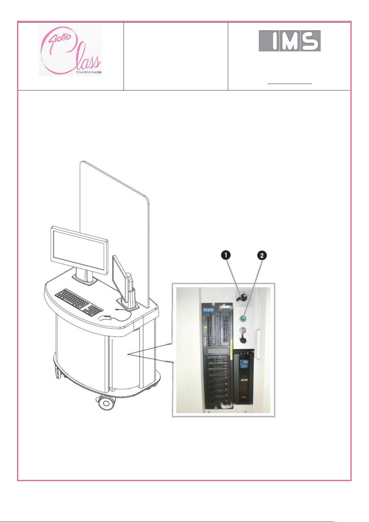
1.3.1. Control and signals
The acquisition workstation has a main switch 1, an engage circuits push button 2 and a touch
screen panel 3 that is used to control and monitor the appliance. The touch screen panel displays
set parameters and alarm messages.
M189_EN:Safety
Draft version_0.1 del 01/07/15

SERVICE AND
INSTALLATION
MANUAL
Via Sagittario 5 - 40037
Pontecchio Marconi (Bo)
Tel. ++39 051 846851
Fax. ++39 051 846856
www.imsitaly.com
pag 19 of 201
1.4. General Safety precautions
• The device may be dangerous to the patient and operator if the X-ray exposure values and
operating instructions are not respected. Observe all operating and safety instructions before
performing an X-ray exam.
• Check the following before installation: observance of minimal safety regulations, location and
operating efficiency of the equipment, measuring ambient conditions (temperature, humidity and
lighting) and checking the suitability of the work space.
• Always work with suitable clothing and the required personal protective equipment.
• While X-rays are being emitted, the operator must remain shielded behind the X-ray lead glass
panel supplied with the vertical X-ray unit (GANTRY).
1.5. Protection and safety regulation
• The person who is about to activate the radiological device must check that nobody else is in the
room, that the doors are closed and that all those present are protected by walls or by shielded
doors.
• During X-ray emissions, always stay behind the X-ray lead glass panel.
• Whenever necessary, always wear the personal dose-meter.
• Reduce the size of the beam and the value of the radiological parameters to a minimum (voltage,
current and radiography time) in so far as they are compatible with the diagnostic needs.
1.6. Warnings and precaustions
• The following is strictly forbidden: tampering with the equipment, controls and safety devices.
• Any modifications or tampering, however slight. The use of non-original spare parts, or spare
parts that are not compatible with the quality standards and electro-mechanical characteristics
specified by the Manufacturer, shall relieve the Manufacturer of all liability and shall void the
warranty rights.
• It is strictly forbidden to place and/or leave objects or anything else not foreseen by the
Manufacturer on the equipment that is potentially harmful to the safety of persons or the integrity of
the equipment.
• Carefully read the steps in this manual that are marked: “INFORMATION” and “CAUTION”.
• If you have any requests, always indicate the model and serial number of the equipment.
• Access to the workstation is password protected.
• It is forbidden to modify the configuration of the workstation.
M189_EN:Safety
Draft version_0.1 del 01/07/15
SERVICE AND
INSTALLATION
MANUAL
Via Sagittario 5 - 40037
Pontecchio Marconi (Bo)
Tel. ++39 051 846851
Fax. ++39 051 846856
www.imsitaly.com
pag 20 of 201
CAUTION!
It is strictly forbidden to operate the equipment if it is not permanently fixed to
the floor. Refer to the relative Section.
Mechanical group
List of screws
Reference draw
• It is forbidden to install software different from the original software that was installed by I.M.S.
S.r.l. service personnel.
• The workstation can be connected to a LAN/WAN network, but the user is responsible for
protecting against viruses, intrusions or data leaks.
• The AWS acquisition workstation TFT monitor can only be used for QA before diagnosis. No
clinical evaluation is allowed.
• Diagnosis can be done both through analysis of laser printed images and the images on the
workstation of reporting workstation (RWS) (optional). The monitor type and performance must
comply with the I.M.S. S.r.l. specifications.
• The “DICOM CD” function of the “Raffaello” appliction software is not built for the permanent
filing of data.
This function is only used for data transfer.
• The “Raffaello” application software installed on the AWS acquisition workstation is able to
store a certain number of examinations (the number depends on the capacity of the hard disks).
This archive is not a legal archive, so any lost data is not the responsibility of I.M.S. S.r.l..
1.6.1. Mechanical safety
The assembly procedure of some part of the device can be critical for the functionality of the device
itself and to assure the safety performance of fine movement.
Following the list of screws and bolt must be used for each critical mechanical group.
M189_EN:Safety
Draft version_0.1 del 01/07/15
SERVICE AND
INSTALLATION
MANUAL
Via Sagittario 5 - 40037
Pontecchio Marconi (Bo)
Tel. ++39 051 846851
Fax. ++39 051 846856
www.imsitaly.com
pag 21 of 201
CAUTION!
X-ray machines can be extremely dangerous to the patient and the operator if
the specified protective measures are not scrupulously observed
1.7. General safety warning
The device was designed and built in compliance with the most severe safety Regulations and left
our production plant in perfect working order. In order to ensure that these conditions are
maintained and that the device is used correctly, the technician must follow the instructions
contained in this manual.
RESIDUAL RISKS
• Although the equipment described in this manual was built in full compliance with the most
severe safety Regulations, the emission of X-rays is a potential hazard and the equipment
therefore cannot be used or handled by unappointed, unqualified, or unauthorized personnel.
• Over-exposure to X-rays can cause serious damage to the human body.
• Although X-ray radiation is in itself dangerous, the GIOTTO TOMO equipment does not cause
any dangerous conditions if used correctly.
• It is therefore essential that all technical and healthcare personnel be suitably informed and
instructed with regard to the hazards of X-ray exposure.
1.8. Radiation protection warnings
• Exposure to X-rays is a health hazard, and therefore great care should be taken in using
adequate means of protection. Radiation can accumulate over time and its effects can be
manifested after many years.
• Primary radiation is the most dangerous kind, therefore, avoid exposure; any object stuck by
primary radiation produces secondary radiation, which is also highly dangerous.
• The unit is equipped with an protective X-ray temperate glass screen coupled to the console,
which protects people against diffused radiation.
1.9. Electrical safety device
• The device must have an electrical supply line equipped with an earth circuit complying to current
Standards.
For any type of simple maintenance, such as cleaning the equipment, always disconnect it from
the mains to avoid damage to persons and/or the electrical - electronic part of the mammography
equipment.
• To ensure the isolation integrity for the system, use only I.M.S. S.r.l. approved accessories on the
equipment. Any changes to the interconnections must be performed by I.M.S. S.r.l. authorized
personnel.
• To ensure proper isolation maintain a 1.5 meter distance between the patient and any
devices not approved for use in the Patient Area. Devices not approved for use in the patient
area (such as the data management computer, the medical recording workstation, laser printers)
must not be installed in this area (see IEC 60601-1-1).
M189_EN:Safety
Draft version_0.1 del 01/07/15
SERVICE AND
INSTALLATION
MANUAL
Via Sagittario 5 - 40037
Pontecchio Marconi (Bo)
Tel. ++39 051 846851
Fax. ++39 051 846856
www.imsitaly.com
pag 22 of 201
CAUTION!
In accordance with EN 60601-1, the unit must be permanently connected to
the electrical mains.
(The protective earth conductor must be connected directly to the protective
earth terminal of the electrical panel).
INFORMATION
A test report shall be filed in I.M.S. S.r.l. archive.
1.10. Exsplosion hazard
• Gas or flammable vapors cannot be used with this equipment.
• Some types of disinfectants could vaporize, thus forming an explosive mixture. If used, they must
be allowed to disperse before powering up the equipment.
1.11. Risk associated witj cleaning the device
• Gas or flammable vapors cannot be used with this equipment.
• Some types of disinfectants could vaporize, thus forming an explosive mixture. If used, they must
be allowed to disperse before powering up the equipment.
1.12. X-ray emission safety
The device uses two separate methods to assure that the generator doesn’t exceed the maximum
exposure limit.
a) A software counter that includes the anode current over time and stops the exposure when the
maximum time has been reached; the counter is protected by a watch dog circuit.
b) A hardware counter that cuts off the electrical power supply to the generator if the maximum
allowed exposure time is exceeded.
1.13. Regulations, laws and normative reference
If there are regulations with legal implications for the installation and/or use of the device, the
installer and user must respect them. The national standards must be respected in every country.
With the exception of that given in this manual, the values can be set based on the national
standards.
This product has the CE marking in conformance with the provisions contained in directive
93/42/EEC of 14 June 1993 concerning medical devices,
Personal data are protected.
Please respect the regulations pertaining to this matter. During the manufacturing phase, the
equipment is checked according to applicable product standards.
The tests to be performed at the equipment installation site are the responsibility of the customer.
M189_EN:Safety
Draft version_0.1 del 01/07/15
SERVICE AND
INSTALLATION
MANUAL
Via Sagittario 5 - 40037
Pontecchio Marconi (Bo)
Tel. ++39 051 846851
Fax. ++39 051 846856
www.imsitaly.com
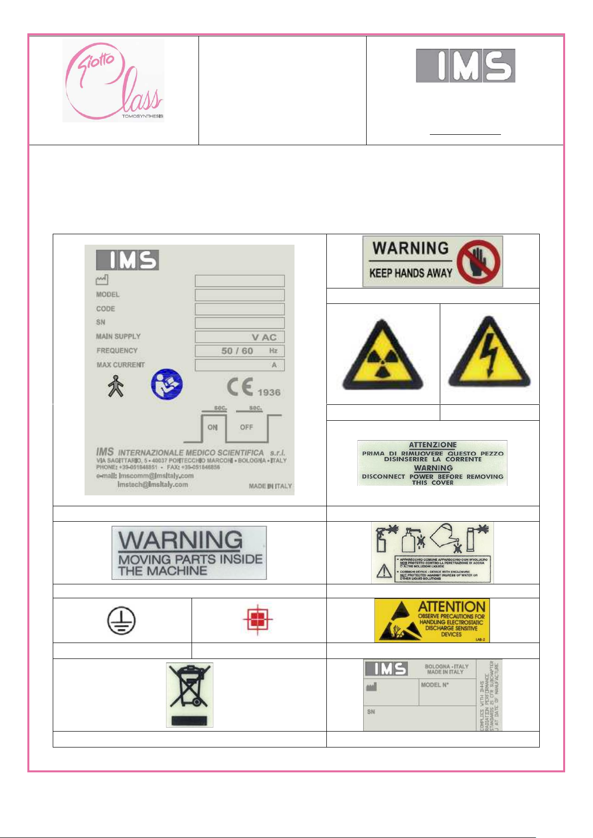
pag 23 of 201
Keep the hands away
Radiation
High Tension
Main Identification label
Parts under voltage
Moving part
IPX0 Protection class label
Earth point
Focal Spot
Electrostatic discharge
WEEE Label
Component Identification
2. General Information
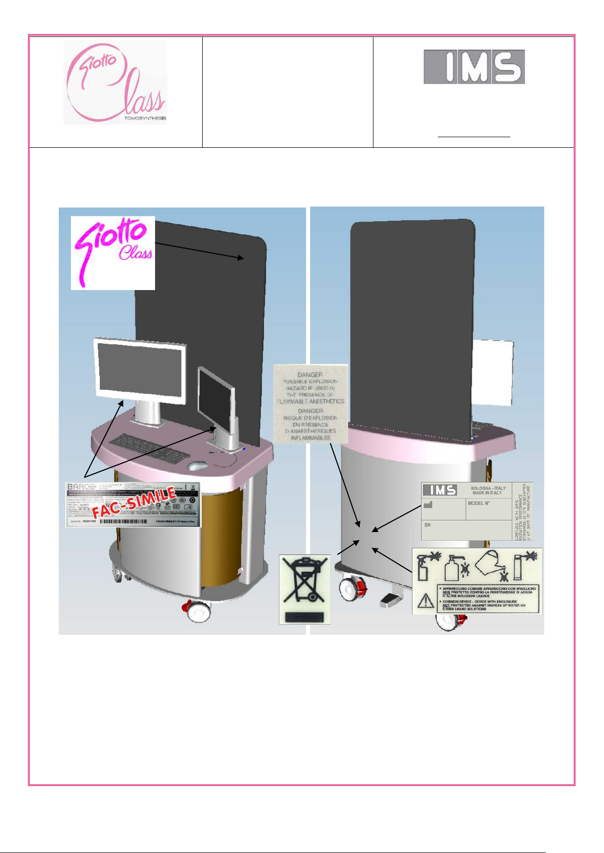
2.1. Labels
M189_EN:General Information
Draft version_0.1 del 01/07/15
SERVICE AND
INSTALLATION
MANUAL
Via Sagittario 5 - 40037
Pontecchio Marconi (Bo)
Tel. ++39 051 846851
Fax. ++39 051 846856
www.imsitaly.com
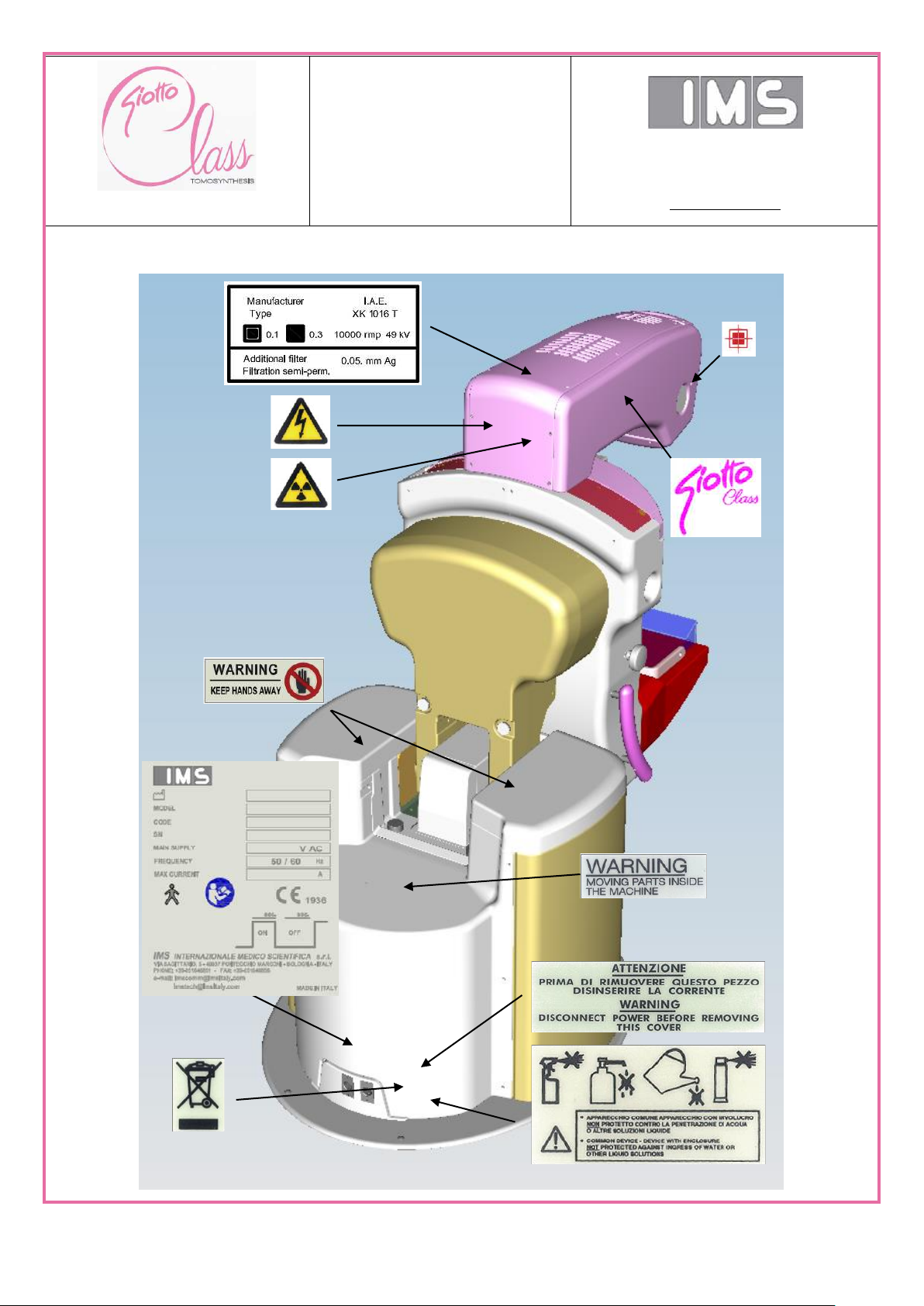
pag 24 of 201
2.1.1. Labels on the X-ray unit
M189_EN:General Information
Draft version_0.1 del 01/07/15
SERVICE AND
INSTALLATION
MANUAL
Via Sagittario 5 - 40037
Pontecchio Marconi (Bo)
Tel. ++39 051 846851
Fax. ++39 051 846856
www.imsitaly.com
pag 25 of 201
M189_EN:General Information
Draft version_0.1 del 01/07/15
SERVICE AND
INSTALLATION
MANUAL
Via Sagittario 5 - 40037
Pontecchio Marconi (Bo)
Tel. ++39 051 846851
Fax. ++39 051 846856
www.imsitaly.com
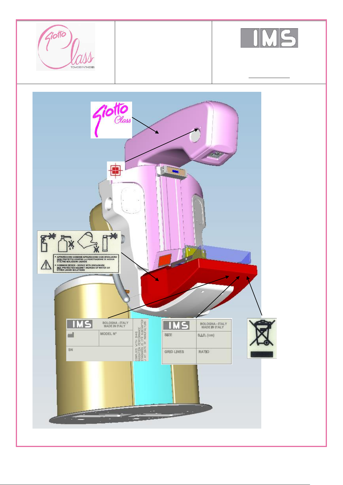
pag 26 of 201
2.1.2. Labels on the operator console (AWS)
M189_EN:General Information
Draft version_0.1 del 01/07/15
SERVICE AND
INSTALLATION
MANUAL
Via Sagittario 5 - 40037
Pontecchio Marconi (Bo)
Tel. ++39 051 846851
Fax. ++39 051 846856
www.imsitaly.com
pag 27 of 201
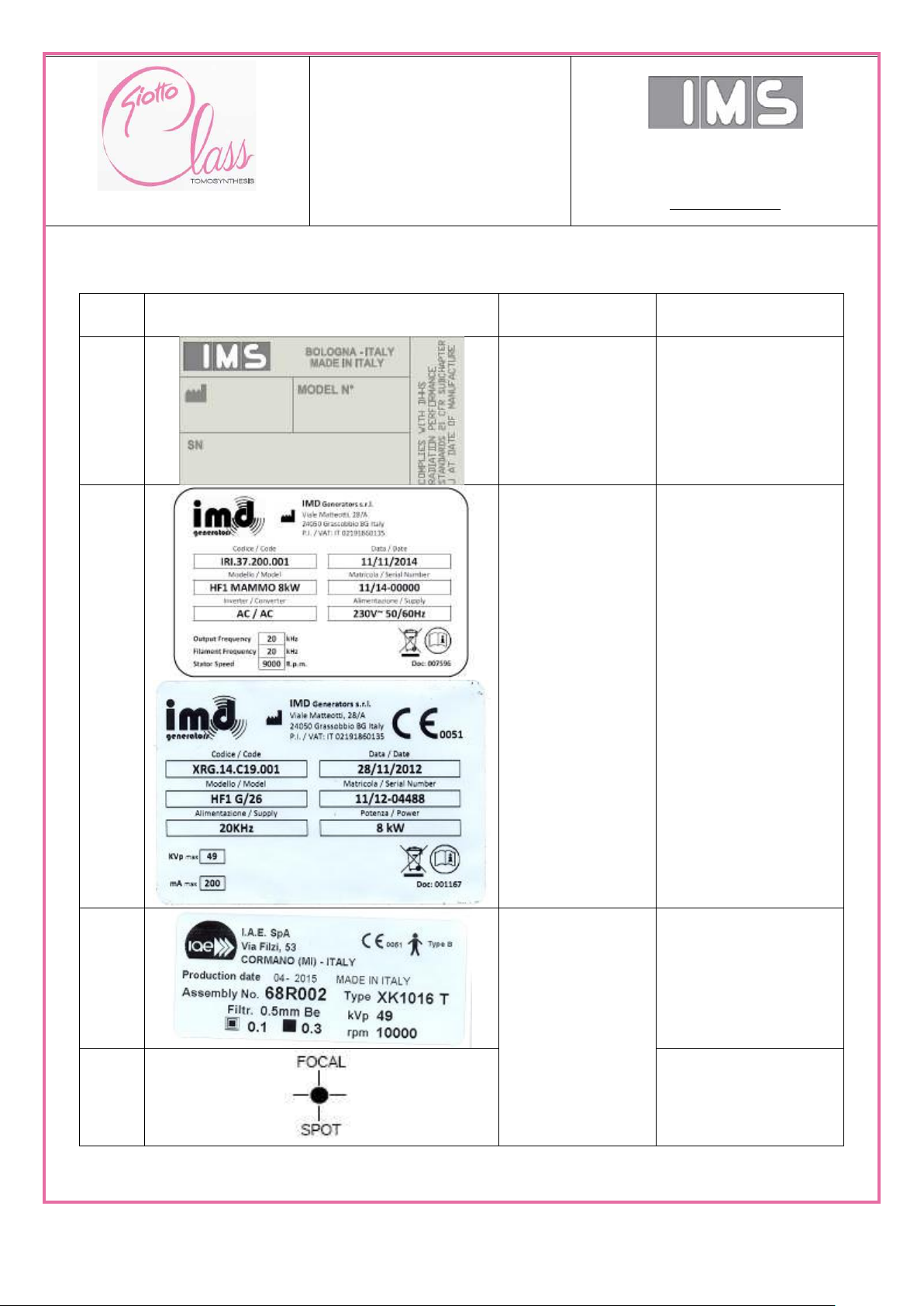
Label
ID
Label
Component
Description
1
IMS accessory
Identification data
2
High-Voltage
Generator
Identification data
3
X-ray tube:
Identification data
4
Focal spot position
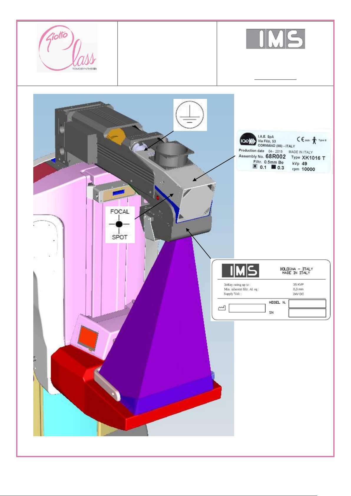
2.1.3. Labels on the internal component
M189_EN:General Information
Draft version_0.1 del 01/07/15

SERVICE AND
INSTALLATION
MANUAL
Via Sagittario 5 - 40037
Pontecchio Marconi (Bo)
Tel. ++39 051 846851
Fax. ++39 051 846856
www.imsitaly.com
pag 28 of 201
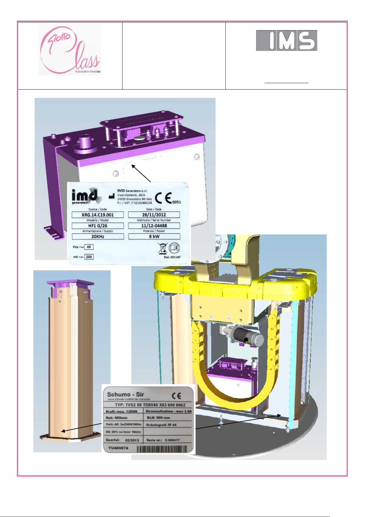
Label
ID
Label
Component
Description
4
Earth point
5
Vertical
movement motor
Identification data
6
Anti-scatter grid
Identification and
specifications data
7
INSERIRE IMMAGINE CON
IDENTIFICAZIONE E HVL
Collimator
Identification and
specifications data
8
Monitor
Identification data
M189_EN:General Information
Draft version_0.1 del 01/07/15
SERVICE AND
INSTALLATION
MANUAL
Via Sagittario 5 - 40037
Pontecchio Marconi (Bo)
Tel. ++39 051 846851
Fax. ++39 051 846856
www.imsitaly.com
pag 29 of 201
M189_EN:General Information
Draft version_0.1 del 01/07/15
SERVICE AND
INSTALLATION
MANUAL
Via Sagittario 5 - 40037
Pontecchio Marconi (Bo)
Tel. ++39 051 846851
Fax. ++39 051 846856
www.imsitaly.com
pag 30 of 201
M189_EN:General Information
Draft version_0.1 del 01/07/15

SERVICE AND
INSTALLATION
MANUAL
Via Sagittario 5 - 40037
Pontecchio Marconi (Bo)
Tel. ++39 051 846851
Fax. ++39 051 846856
www.imsitaly.com
pag 31 of 201
Min
Max
Humidity
10%
80%
Temperature
-10 °C = 14 °F
80 °C = 176 °F
Atmospheric pressure
700 hPa
1060 hPa
WARNING
If the equipment is stored while packed, do not stack the packing crates on top of one
another.
Min
Max
Humidity
10%
95%
Temperature
5 °C = 41 °F
45 °C = 113 °F
Atmospheric pressure
700 hPa
1060 hPa
WARNING
If the equipment is stored while packed, do not stack the packing crates on top of one
another.
CAUTION
Do not stack other crates on top of the digital detector crate!!!
CAUTION
If the temperature is below 5 °C or is over 45 °C, there is a risk of permanent damage
to the digital detector.
2.2. Technical data
The equipment can only be used in rooms designed for medical use.
The current national standards apply. In order to ensure the safety of users, patients and third
parties, it is recommended that you fully comply with the standards mentioned in this document
(unless they are inconsistent with the national standards).
THIS IS A DRAFT VERSION; ALL THE DATA WITH THE * MARK ARE UNDER REVISION.
2.2.1.1. X-ray unit and operator console storage conditions
2.2.1.1. Digital image receptor storage conditions
M189_EN:General Information
Draft version_0.1 del 01/07/15

SERVICE AND
INSTALLATION
MANUAL
Via Sagittario 5 - 40037
Pontecchio Marconi (Bo)
Tel. ++39 051 846851
Fax. ++39 051 846856
www.imsitaly.com
pag 32 of 201
Temperature range
From +12 °C to +27 °C.
If the detector internal temperature drops below 5 °C or exceeds
45 °C, there is a risk that the detector may be permanently
damaged.
Maximum ratio
0 °C in 20 minutes
Relative humidity
range
Up to 95% non condensing
Maximum warm-up
time for operation
10 minutes
Tension
230 VAC ± 10%, 50/60 Hz ± 5%,
single phase, permanent connection
Maximum Power
25 A – 230 VAC duty cycle 3s ON 60s OFF*
Fuses
40 A*
Permanent connection with
protective conductor
Required network filter with minimum attenuation of 10
dB*
2.2.1.2. Operating conditions
2.2.1.3. Enclosures protection class
The Giotto Class is a IPXO protection class device. Device is not sealed, not suitable for
use in the presence of flammable anesthetic mixture from the air, oxygen, or nitrogen
oxides.
2.2.1.4. Electrical power supply
M189_EN:General Information
Draft version_0.1 del 01/07/15

SERVICE AND
INSTALLATION
MANUAL
Via Sagittario 5 - 40037
Pontecchio Marconi (Bo)
Tel. ++39 051 846851
Fax. ++39 051 846856
www.imsitaly.com
pag 33 of 201
Vertical movement
Total 630 mm (850 mm with consequence of inclination
movement)
Potter/Bucky - Floor:
(unit in vertical position)
Min: 630 mm
Max: 1260 mm
Potter/Bucky - Floor:
(unit in horizontal position)
Min: 1360 mm
Max: 1990 mm
Gantry rotation range
- 177.0° / + 177.0° (Motorized)
Gantry inclination range
- 15.0° / + 90.0 ° (Motorized)
Angular range of emission
- 14.5° / + 14.5 ° (Motorized)
Source-to-Image Distance (SID)
685 mm
Source-to-Breast Support Distance
668 mm
Magnification factor
1.8 X (optional)
Dimension of x-ray unit
(H x W x D)
147.6 x 80.0 x 149.8 cm (in vertical position)
Dimension of operator console unit
(H x W x D)
195.0 x 88.6 x 66.0 cm *
Weight of x-ray unit
270 kg
Weight of operator console unit
120 kg
Weight of Flexi Table
250 kg
2.2.1.5. X-ray unit specifications
M189_EN:General Information
Draft version_0.1 del 01/07/15

SERVICE AND
INSTALLATION
MANUAL
Via Sagittario 5 - 40037
Pontecchio Marconi (Bo)
Tel. ++39 051 846851
Fax. ++39 051 846856
www.imsitaly.com
pag 34 of 201
SOURCE-to-IMAGE DISTANCE (SID), DIRECT FOCAL DISTANCE, and SOURCE-to AXIS
ROTATION DISTANCE (SAD)
M189_EN:General Information
Draft version_0.1 del 01/07/15

SERVICE AND
INSTALLATION
MANUAL
Via Sagittario 5 - 40037
Pontecchio Marconi (Bo)
Tel. ++39 051 846851
Fax. ++39 051 846856
www.imsitaly.com
pag 35 of 201
Actuator type
Stepper Motor - Pedal or Manually with control knob
Maximum compressor force
200 N (motorized) 300 N (manual)
Minimum Force for AEC activation
5 N
Compression Force accuracy
± 1 kg
Compression Thickness
± 2 mm
Release after exposure
Automatic or manually in case of inhibition by operator
Compression velocity
2 mm/s during approaching 1 mm/s during compression *
Compressor plates material
PET-G
Compressor plate maximum flexion
< 5 mm for asymmetric compression
Compressor plate absorption
16.5% ÷ 0.003 mm Al for 28 kV W/Ag
2.2.1.6. Breast compression system
M189_EN:General Information
Draft version_0.1 del 01/07/15

SERVICE AND
INSTALLATION
MANUAL
Via Sagittario 5 - 40037
Pontecchio Marconi (Bo)
Tel. ++39 051 846851
Fax. ++39 051 846856
www.imsitaly.com
pag 36 of 201
Manufacturer
IMD Generators
Model
HF1 Mammo 8kW
Input power supply
(Inverter + Filament +
Stator power supply)
Single phase 230VAC 50/60Hz
Rated input max power
11 kVApk (max 32Apk) Depending on the exposure
parameters
Max input current
protection breakers
32A 400 Vac aM 20 kA
Recommended thermomagnetic circuit breaker
Un = 230 Vac 50/60 Hz
In = 32 A;
Number of poles = 2
Protection class
C as per IEC-EN 60898
Power output
Single phase 20 kHz (Max 210 VAC
rms
)
Filament power board
output:
Single phase 16 kHz (Max 5.5 A
rms
)
Stator driver power board
output:
Single phase + shifted phase 150 Hz (Max 230 VAC
rms
/ 7Apk)
Inverter
Pulsed load output power
8 kW (200mA @ 40 kV 0,1 sec)
kV Range
22 - 49 kVDC
Max Ripple
< 1%
Max RAD mode load
output
200 mA @ 40 kV (0,1 sec)
Max frame per second rate
30 fps
Filament
Max load output power
65VA (5A @ 13V)
Stator driver
Steady state nominal
power
280 VA
Maximum surge power
(launch max 1msec)
1600 VA
2.2.1.7. High Voltage Generator specifications
M189_EN:General Information
Draft version_0.1 del 01/07/15

SERVICE AND
INSTALLATION
MANUAL
Via Sagittario 5 - 40037
Pontecchio Marconi (Bo)
Tel. ++39 051 846851
Fax. ++39 051 846856
www.imsitaly.com
pag 37 of 201
M189_EN:General Information
Draft version_0.1 del 01/07/15
High Voltage Generator Electrical connections

SERVICE AND
INSTALLATION
MANUAL
Via Sagittario 5 - 40037
Pontecchio Marconi (Bo)
Tel. ++39 051 846851
Fax. ++39 051 846856
www.imsitaly.com
pag 38 of 201
Terminals
Input / Output characteristic
CP1-1,2
Input power supply
(Inverter + Filament + Stator power
supply)
Single phase
230Vac 50/60Hz
Rated input max power
11kVApk
(max 32Apk)
Depending on the exposure
parameters
Max input current protection breakers
32A 400Vac aM 20kA
Recommended thermo-magnetic
circuit breaker
Un = 230Vac 50/60Hz
In = 32A
Number of poles = 2
Protection class = C
as per IEC-EN 60898
GND Screw
GND
Connected to the
Control unit chassis
CP2-1,2
Power output
Single phase
20kHz
(Max 210Vacrms )
CP3,1: (LF)
CP3,2: (SF)
CP3,3: (CM)
CP3,4: GND
Filament power board output:
(LF) = Large Focus
(SF) = Small focus
(CM) = Common
Single phase
16kHz
(Max 5.5Arms)
CP3,5: (P)
CP3,6: (S)
CP3,7: (C)
CP3,8: GND
Stator driver power board output:
(P) = Main phase
(S) = Shifted
(C) = Common
Single phase +
shifted phase
150Hz
(Max 230Vacrms / 7Apk)
2.2.1.8. High Voltage Generator Electric characteristics and I/O (power and
signals)
All the control unit interface connectors are from Molex (except power GND).
In order to connect the unit, following headers are needed:
CP1 = 2ways Minifit SR 42816 series connector
CP2 = 3ways Minifit SR 42816 series connector
CP3 = 8ways (4x2) Minifit Jr 5557 series connector
CP4 = 3ways Microfit 43645 series connector
CP5 = 4ways (2x2) Microfit 43645 series connector
CP6 = 6ways (3x2) Microfit 43020 series connector
GND = M5 brass nut
M189_EN:General Information
Draft version_0.1 del 01/07/15

SERVICE AND
INSTALLATION
MANUAL
Via Sagittario 5 - 40037
Pontecchio Marconi (Bo)
Tel. ++39 051 846851
Fax. ++39 051 846856
www.imsitaly.com
pag 39 of 201
Terminals
Signal
Block diagram
1,3
(CP4-2: GND)
INPUT
CAN BUS
CP5-1,2
INPUT
Digital*
Command
X-Ray
CP5-3,4
OUTPUT
Digital*
HV > 85%
CP6-4,5
INPUT
Digital
Thermal safety
switch
This input manages the normally closed contact which comes
from the safety switch in the HV transformer.
CP6-1 mA+
CP6-2 mA-
INPUT
Analog
Feedback Anodic
mA
These inputs have to be connected to the load as indicated in
the chapter 8.3
Transport and storage conditions
Range of temperature
0° – 50° C
Relative humidity (non condensing)
20 – 90 %
Atmospheric pressure
700 – 1060 hPa
Working conditions
Range of temperature
10° – 40° C
Relative humidity (non condensing)
30 – 75 %
Atmospheric pressure
700 – 1060 hPa
2.2.1.9. High Voltage Generator: conditions of storage and usage
M189_EN:General Information
Draft version_0.1 del 01/07/15

SERVICE AND
INSTALLATION
MANUAL
Via Sagittario 5 - 40037
Pontecchio Marconi (Bo)
Tel. ++39 051 846851
Fax. ++39 051 846856
www.imsitaly.com
pag 40 of 201
2.2.1.10. X-ray tube assembly
M189_EN:General Information
Draft version_0.1 del 01/07/15

SERVICE AND
INSTALLATION
MANUAL
Via Sagittario 5 - 40037
Pontecchio Marconi (Bo)
Tel. ++39 051 846851
Fax. ++39 051 846856
www.imsitaly.com
pag 41 of 201
Manufacturer
I.A.E.
Model
XK116T
Focal Spot dimension
0.1-0.3 mm
Anode Angles
10°-16°
Anode rotation speed
3000-10000 rpm
Anodic Material
RT-TZM
Inherent Filtration
0.5 mm Be
Termal Anodic capacity
225 kJ - 300 kHU
Continuous anode heat dissipation
715 W
Maximum anode heat dissipation
750 W
Equivalent anode input power
100 W - 38% of max
Dimensions
110 x 155 x 305 mm
Weight
5.5 kg
Temperature condition
for transportation and storage
-10 / + 80 °C
Humidity condition
for transportation and storage
max 80 %
Maximum High Tension
49 kV
Maximum heat dissipation with fan
300 W
Maximum leakage radiation
at 1 m from focal spots
63 uGy/h - 7 mR/h
93/42/CEE Classification
IIb
IEC 60601-1 equipment class
I
IEC 60601-1 equipment type
B
M189_EN:General Information
Draft version_0.1 del 01/07/15

SERVICE AND
INSTALLATION
MANUAL
Via Sagittario 5 - 40037
Pontecchio Marconi (Bo)
Tel. ++39 051 846851
Fax. ++39 051 846856
www.imsitaly.com
pag 42 of 201
M189_EN:General Information
Draft version_0.1 del 01/07/15

SERVICE AND
INSTALLATION
MANUAL
Via Sagittario 5 - 40037
Pontecchio Marconi (Bo)
Tel. ++39 051 846851
Fax. ++39 051 846856
www.imsitaly.com
pag 43 of 201
M189_EN:General Information
Draft version_0.1 del 01/07/15

SERVICE AND
INSTALLATION
MANUAL
Via Sagittario 5 - 40037
Pontecchio Marconi (Bo)
Tel. ++39 051 846851
Fax. ++39 051 846856
www.imsitaly.com
pag 44 of 201
M189_EN:General Information
Draft version_0.1 del 01/07/15

SERVICE AND
INSTALLATION
MANUAL
Via Sagittario 5 - 40037
Pontecchio Marconi (Bo)
Tel. ++39 051 846851
Fax. ++39 051 846856
www.imsitaly.com
pag 45 of 201
M189_EN:General Information
Draft version_0.1 del 01/07/15

SERVICE AND
INSTALLATION
MANUAL
Via Sagittario 5 - 40037
Pontecchio Marconi (Bo)
Tel. ++39 051 846851
Fax. ++39 051 846856
www.imsitaly.com
pag 46 of 201
kV
Large Focus (0.3mm2) - mA
Small Focus (0.1mm2) - mA
22
110
41
23
115
42
24
120
43
25
125
44
26
130
45
27
135
46
28
140
47
29
145
46
30
150
45
31
155
44
32
150
43
33
145
42
34
140
41
35
135
40
Range kV/mA
* Data under revision
Range current-time product (mAs):
- LARGE FUOCUS (0.3 mm2) 2-600 mAs with steps of 1 mAs
- SMALL FOCUS (0.1 mm2) 2-185 mAs with steps of 1 mAs
The Giotto Class unit does not apply the loading factors from TABLES R10 – R20.
M189_EN:General Information
Draft version_0.1 del 01/07/15

SERVICE AND
INSTALLATION
MANUAL
Via Sagittario 5 - 40037
Pontecchio Marconi (Bo)
Tel. ++39 051 846851
Fax. ++39 051 846856
www.imsitaly.com
pag 47 of 201
Material
Silver (Ag)
Thickness
0.0050 ± 5 mm
Purity
≥ 99.9 %
Half-Value Layer (HVL)
W/Ag (50 m)
25 kV = 0.48 ± 0.02 mm Al *
28 kV = 0.53 ± 0.02 mm Al *
31 kV = 0.57 ± 0.02 mm Al *
Reproducibility
< 5%
Linearity
R2> 0.999
kV accuracy
± 1 kV of nominal value
mAs accuracy
± 5% o ± 1mAs of nominal value
Dose output
~ 1 mGy for 26 kV W/Ag 20 mAs at SID distance
(~ 7.0 mGy/s at 685 mm from source); *
Light field source
LED + mylar mirror
Light field intensity
> 160 lux
Light field activation
Single pressure of keyboard button or when compressor is moving
with pedal
Light field duration
20 s
X-ray field / Light field
misalignment
< 2 % of SID according to IEC 60601-2-45
2.2.1.11. X-ray beam filtration
2.2.1.12. Radiation Output
2.2.1.13. Beam Limiting device
Automatic collimation depending on the compressor format and angle of emission.
The image dimension is depending on the collimation format (collimation diaphragm never
visible)
M189_EN:General Information
Draft version_0.1 del 01/07/15

SERVICE AND
INSTALLATION
MANUAL
Via Sagittario 5 - 40037
Pontecchio Marconi (Bo)
Tel. ++39 051 846851
Fax. ++39 051 846856
www.imsitaly.com
pag 48 of 201
Operator protection
Anti-X ray Protective barrier
Anti-X ray protective barrier
material and dimension
Temperate glass 760 x 1960 x 5 mm
Equivalent filtration
The protective barrier installed on the control cabinet guaranties an
equivalent absorption of 0.1 mm Pb as required by IEC 60601-1-3
and IEC 60601-2-45 standards.
Patient protection
Patient face protection
Automatic collimator
AEC system
Operating system
WINDOWS 7 Embedded SP1
Processor
INTEL DUAL- CPU
Memory RAM
24 GB
Capacity hard drive
1TB or superior, DVD READER/BURNER
Graphic board
Integrated display port
LCD Display
1600x1200 – 20” da 180 cd/m
2
Optional Diagnostic 3 MP
Network interface
3GB Ethernet
Remote diagnostic
Internet
G.U.I.
Machine state
Work-list modality
Patient data management
Brightness and contrast control
Magnification Lens
Tomosynthesis scroll tools with kinetic modality
Q.A. test tools
Biopsy examination modalities
Digital Images Formats
DICOM 3.0
– See Informance Statement
DICOM Functions
Verification SCU/SCP Store SCU/SCP Query /retrieve SCU Print
SCU WORKLIST CU STORAGE COMMITMENT SCU MPPS SCU *
Image processing and
reconstructions
RAFFAELLO software
2.2.1.14. Radiation Protection
2.2.1.15. Acquisition Work Station (AWS)
M189_EN:General Information
Draft version_0.1 del 01/07/15

SERVICE AND
INSTALLATION
MANUAL
Via Sagittario 5 - 40037
Pontecchio Marconi (Bo)
Tel. ++39 051 846851
Fax. ++39 051 846856
www.imsitaly.com
pag 49 of 201
Manufacturer
Analogic
Model
AXS-2430
Sensor Physical
Dimensions
239.36 x 304.64 mm
Active Area
2816 x 3584 pixels
Image matrix
2812 x 3580 pixels
N.B. The first two lines and columns at the edge of the active area are declared dead
Pixel size
0.085 x 0.085 mm
Geometric Fill Factor
88%
Detection Method
Direct Conversion (DR) using Amorphous Selenium (a-Se)
Read out technology
TFT array
Saturation Dose
~ 3.0 mGy (mammographic context)
~ 0.7 mGy (tomosynthesis context)
Response
Linear (R2 > 0.99)
DQE @ 1lp/mm
> 50 %
DQE @ 5.8 lp/mm
> 20 %
MTF @ 1lp/mm
> 90 %
MTF @ 5.8 lp/mm
> 40 %
Lag
< 0.005 after 30 s
Ghost
0.05 (Euref Method)
ACR Mammography
Accreditation Phantom
≥ 4 Masses
≥ 3 Fibres
≥ 3 Speck goups
For every modality of acquisition
(MAMMO, TOMO, COMBO) using the AEC system
ADC Bit depth
16 bits min
Image bit depth
13 Bit for mammographic and projections images
14 Bit for reconstruction
Image dimension
19 MB for mammographic and projections images
Depending on the volumetric reconstruction dimension
Maximum defective pixels
< 5000
Maximum correctable
defective lines/columns
< 10
Maximum correctable
defective cluster
150 cluster (max 8 pixel)
2.2.1.16. Digital image receptor
M189_EN:General Information
Draft version_0.1 del 01/07/15

SERVICE AND
INSTALLATION
MANUAL
Via Sagittario 5 - 40037
Pontecchio Marconi (Bo)
Tel. ++39 051 846851
Fax. ++39 051 846856
www.imsitaly.com
pag 50 of 201
Principle of function
The compressed breast thickness determinate the optimum values
of the kV and mAs for the pre-exposure (for tomosynthesis scan the
first exposure id used as pre-exposure) Analyzing the image
received the AWS determinates the maximum density inside the
breast and select the mAs needed.
Sensible areas
The analysis area is rectangular, aligned with chest wall and laterally
centered.
1. 2D Mammo : 15 cm x 19 cm
2. 3D Tomo : 10 cm x 19 cm
3. Biopsy : 4 cm x 1 cm
Techniques
- Manual: manual selection of kV, filter, mAs
- Automatic: automatic selection of Focus type, kV, filter, mAs
Short term reproducibility
< ± 5%
Long term reproducibility
< ± 10%
Manufacturer
JPI Healthcare solution
Model
2100
Type
linear focused grid
Ratio
4 : 1
Line density
31 lp / cm
Focal Distance
65 cm
Interspace material
Pure carbon ( C )
Absorbed material
Lead alloy ( Pb )
Cover material
CFRP
Application limit (f1 ~ f2)
43 ~ 180 cm
Transmission of primary
radiation (Tp)
73%
Transmission of scatter
radiation (Ts)
26%
Transmission of total
radiation (Tt)
58%
Grid selectivity (Σ)
2.81 ± 5%
Contrast improvement
fator (K)
1.26 ± 5%
Grid exposure factor (B):
1.72 ± 10%
2.2.1.17. Automatic Exposure Ccontrol (AEC) system
2.2.1.18. Anti-scatter grid
M189_EN:General Information
Draft version_0.1 del 01/07/15

SERVICE AND
INSTALLATION
MANUAL
Via Sagittario 5 - 40037
Pontecchio Marconi (Bo)
Tel. ++39 051 846851
Fax. ++39 051 846856
www.imsitaly.com
pag 51 of 201
Max Height
2320 mm
Isocentric height
30 mm over the detector support
Breast support height
70 - 145 (± 2) cm
Source-to-image distance (SID)
690 mm
Gantry rotation range
+180° (in anticlockwise) -120° (in clockwise)
Weight
450 kg
2.2.1.19. Dimension of the X-ray unit
M189_EN:General Information
Draft version_0.1 del 01/07/15

SERVICE AND
INSTALLATION
MANUAL
Via Sagittario 5 - 40037
Pontecchio Marconi (Bo)
Tel. ++39 051 846851
Fax. ++39 051 846856
www.imsitaly.com
pag 52 of 201
Dimension (H x W x D)
1982 x 886 x 660 mm
Weight
180 kg
2.2.1.20. Dimension of the opreator console unit
M189_EN:General Information
Draft version_0.1 del 01/07/15

SERVICE AND
INSTALLATION
MANUAL
Via Sagittario 5 - 40037
Pontecchio Marconi (Bo)
Tel. ++39 051 846851
Fax. ++39 051 846856
www.imsitaly.com
pag 53 of 201
2.2.2. Electrical connections
M189_EN:General Information
Draft version_0.1 del 01/07/15
Temporary images (is not the final version)

SERVICE AND
INSTALLATION
MANUAL
Via Sagittario 5 - 40037
Pontecchio Marconi (Bo)
Tel. ++39 051 846851
Fax. ++39 051 846856
www.imsitaly.com
pag 54 of 201
CAUTION
In accordance with EN 60601-1, the unit must be permanently connected to the
electrical mains.
(The protective earth conductor must be connected directly to the protective earth
terminal of the electrical panel).
CAUTION
THE UNIT AND IT’S ACCESSORIES MUST ONLY BE INSTALLED AND USED IN
SHIELDED ROOMS (MINIMUM SHIELDING RATIO 20 dB).
INFORMATION
The fixed cables for systems and devices that cannot be disconnected by the user
are not listed. These cables are part of the system and were always taken into
consideration when measuring the EMC. The device or system would not function
without these cables.
CAUTION
Use of accessories, transformers or cables different than those indicated.
Possible increase in the emissions or reduction in the resistance to
disturbances for the device or system!
Use only transformers and cables sold by the manufacturer of the device or system
as replacement parts for the internal components.
2.2.3. Warning on electromagnetic compatibility (EMC)
The unit is certified as a fixed installation electro medical device and was built in conformity with
the applicable provisions of directive 93/42/EEC concerning medical devices modified by directive
2007/47/EC.
The unit is built in compliance with the IEC 60601-1-2 standard.
M189_EN:General Information
Draft version_0.1 del 01/07/15

SERVICE AND
INSTALLATION
MANUAL
Via Sagittario 5 - 40037
Pontecchio Marconi (Bo)
Tel. ++39 051 846851
Fax. ++39 051 846856
www.imsitaly.com
pag 55 of 201
Measurement of the
emission
disturbances
Compliance
Guidelines - Electromagnetic Environment
Conducted RF
Radiated RF
CISPR 11
Group 1
The system uses HF energy only for its internal
functioning. Therefore its HF emissions are very low and
are not likely to cause any interference in nearby
electronic equipment.
Conducted RF
Radiated RF
CISPR 11
Class A
The unit/system is suitable for use in all environments
other than domestic and those directly connected to
the public low voltage power supply network that
supply buildings used for domestic purposes.
The system has a nominal input current greater than 16 A
per phase.
Harmonic emissions
IEC 61000-3-2
Not applicable
Voltage
fluctuations/flicker
IEC 61000-3-3
Not applicable
2.2.4. Manufacturer’s declaration and guidelines - Electromagnetic emissions
The system is intended for operation in an electromagnetic environment indicated below. The
customer or user of the system must ensure that it is used within this environment.
M189_EN:General Information
Draft version_0.1 del 01/07/15

SERVICE AND
INSTALLATION
MANUAL
Via Sagittario 5 - 40037
Pontecchio Marconi (Bo)
Tel. ++39 051 846851
Fax. ++39 051 846856
www.imsitaly.com
pag 56 of 201
Electromagnetic
interference tests
Test level -
IEC 60601
Compliance
level
Electromagnetic environment -
guidelines
Electrostatic discharge
(ESD)
IEC 61000-4-2
±6 kV
Contact
discharge
±8 kV
Air discharge
±6 kV
Contact
discharge
±8 kV
Air discharge
Floors should be wood, concrete or ceramic
tile. If floors are covered with synthetic
material, the relative humidity should be at
least 30%.
Electrical fast transient/
burst
IEC 61000-4-4
±2 kV
for power
supply cables
±1 kV
for input and
output cables
±2 kV
for power
supply cables
±1 kV
for input and
output cables
The mains power quality must be that of a
typical commercial or hospital environment.
Surge
IEC 61000-4-5
±1 kV
differential
mode
±2 kV
Common
mode
±1 kV
differential
mode
±2 kV
Common
mode
The mains power quality must be that of a
typical commercial or hospital environment.
Voltage drops, short
term interruptions and
fluctuations in the
supply voltage
IEC 61000-4-11
<5% UT
(> 95% drop
in UT) for 0.5
cycle
40% UT
(> 60% drop
in UT) for 5
cycles
70% UT
(> 30% drop in
UT) for 25
cycles
<5% UT
(> 95% drop
in UT) for 5 s
Not applicable
<5 % UT (>95
% dip in UT)
for half cycle
40 % UT (>60
% dip in UT)
for 5 cycles
70 % UT (>30
% dip in UT)
for 25 cycles
<5 % UT (>95
% dip in UT)
for 5 s
The mains power quality must be that of a
typical commercial or hospital environment. If
the user of the system requires continuous
operation during power outages, it is
recommended that it be powered with an
uninterruptible power supply.
The system has a nominal input current greater
than 16A per phase.
Magnetic field at the
supply frequency (5060 Hz)
IEC 61000-4-8
3 A/m
3 A/m
The magnetic fields at mains frequency should
correspond to the typical values seen in a
typical business or hospital environment.
Note: UT is the alternative current voltage before the application of the test level.
2.2.5. Manufacturer’s declaration and guidelines - Immunity to
electromagnetic interferences
The system is intended for operation in an electromagnetic environment indicated below. The
customer or user of the system must ensure that it is used within this environment.
M189_EN:General Information
Draft version_0.1 del 01/07/15

SERVICE AND
INSTALLATION
MANUAL
Via Sagittario 5 - 40037
Pontecchio Marconi (Bo)
Tel. ++39 051 846851
Fax. ++39 051 846856
www.imsitaly.com
pag 57 of 201
CAUTION
Use of the device or system immediately next to other devices or stacked
on top of other appliances.
Proper operation cannot be guaranteed!
If the device or system must operate alongside other appliances or be
stacked on top of them, it should be execute a functional test to check
that it functions properly in this layout.
Portable and mobile HF communication devices should be used no closer to any part of the
equipment, including cables, than the recommended separation distance. The separation distance
is calculated based on the applicable transmission frequency equation.
P is the maximum nominal power rating of the transmitter in watts (W) according to the transmitter
manufacturer and d is the recommended separation distance in meters (m).
The field strength from the stationary RF transmitter, as determined by a local electromagnetic site
survey a should be less than the compliance level b at each frequency range. Interference may
occur near equipment marked with the following symbol
Electromagnetic
interference tests
Test level - IEC
60601
Compliance
level
Recommended separation
distance:
Conducted HF
interference
IEC 61000-4-6
3 Vrms
from 150 kHz to
80 MHz
3 Vrms
d = 1, 2√P
Radiated HF
interference
IEC 61000-3-2
3 V/m
from 80 MHz to
2,5 GHz
3 V/m
d = 1, 2√P per 80 MHz - 800
MHz
d = 2, 3√P per 800 MHz - 2,5
GHz
Note 1: The higher frequency range applies at 80 MHz and 800 MHz.
Note 2: These guidelines may not be applicable in all cases. The spread of electromagnetic
emissions is affected by the absorption and reflection by buildings, objects and people.
A) The field strengths of stationary transmitters, e.g. base stations for radio telephones
(mobile/cordless) and mobile radio equipment, amateur radio stations, AM and FM radio and television
transmitters cannot be predicted theoretically with accuracy. In order to determine the electromagnetic
environment with regard to stationary transmitters, a study of the location should be carried out. If the
field strengths measured at the location where the system will be used exceed the compliance level
given above, the system should be monitored to see that it operates properly. If unwanted performance
characteristics are observed, additional measures may be necessary, such as reorienting or
repositioning the system.
B) At the frequency range from 150 kHz to 80 MHz, the field strengths should be lower than 3 V/m.
CAUTION
PORTABLE AND MOBILE RADIO COMMUNICATION DEVICES CAN
INFLUENCE THE OPERATION OF THE UNIT AND ITS
ACCESSORIES.
M189_EN:General Information
Draft version_0.1 del 01/07/15

SERVICE AND
INSTALLATION
MANUAL
Via Sagittario 5 - 40037
Pontecchio Marconi (Bo)
Tel. ++39 051 846851
Fax. ++39 051 846856
www.imsitaly.com
pag 58 of 201
Maximum rated output power of
transmitter (W)
Separation distance according to frequency of the
transmitter [m]
da 150 kHz a 80
MHz
d = 1, 2√P
da 80 MHz a 800
MHz
d = 1, 2√P
da 800 MHz a
2,5 GHz
d = 2, 3√P
0,01
0,12
0,12
0,23
0,1
0,38
0,38
0,73
1
1,2
1,2
2,3
10
3,8
3,8
7,3
100
12
12
23
For transmitters rated at a maximum output power not listed above, the recommended separation
distance d in meters (m) can be determined using the equation from the applicable column, where
P is the maximum output power rating of the transmitter in watts (W) according to the transmitter
manufacturer.
Note 1: The higher frequency range applies at 80 MHz and 800 MHz.
Note 2: These guidelines may not be applicable in all cases. The spread of electromagnetic
emissions is affected by the absorption and reflection by buildings, objects and people.
2.2.6. Recommended separation distances between the system and portable
and mobile HF communication devices munication devices
The system is intended for use in an electromagnetic environment in which HF disturbances are
controlled. The customer or the user of the system can help prevent electromagnetic interference.
This can be achieved by maintaining a minimum distance between portable and mobile HF
communication devices (transmitters) and the system, based on the rated maximum output power
of the communication devices.
M189_EN:General Information
Draft version_0.1 del 01/07/15

SERVICE AND
INSTALLATION
MANUAL
Via Sagittario 5 - 40037
Pontecchio Marconi (Bo)
Tel. ++39 051 846851
Fax. ++39 051 846856
www.imsitaly.com
pag 59 of 201
Description
Product Code
Compressor Paddle 24x30 cm for Tomosynthesis scan
XXXXXX
Face protection for mammo
XXXXXX
Face protection for tomo
XXXXXX
Foot switches for vertical movement
XXXXXX
Foot switches for compressor
XXXXXX
Visualization Monitor
XXXXXX
Touch-Screen monitor
XXXXXX
2MP Monitor
XXXXXX
3MP Monitor
XXXXXX
Operator Protection (Glass barrier)
XXXXXX
Description
Product Code
Biopsy unit: Smart Finder
28000-00
Patient support: Flexi Table
29000-00
Review Work Station (RWS) with two 5 MPixel monitors
31010-00
Review Work Station (RWS) with two 5 MPixel monitors + 1 additional
LCD 21.3” 2 MPixel monitor
31020-00
Review Work Station (RWS) with one 10 MPixel monitor
31040-00
Review Work Station (RWS) with one 10 MPixel monitor + 1 additional
LCD 21.3” 2 MPixel monitor
31060-00
Mammographic Compressor Paddle 24x30 cm
25100-00
Compressor Paddle 15x30 cm
25200-00
Compressor Paddle 05x05 cm
25980-00
Compressor Paddle 10x10 cm
25900-00
Magnification Platform with Compressor Paddle 24 x 30 cm
26100-00
Software Raffaello Viewer
31003-00
Software CAD Galileo
31070-00
Software G-View (synthetic 2D image from 3D reconstruction)
31002-00
Supplement foot pedal
25030-00
Wireless foot pedal for vertical movement
25010-10
Wireless foot pedal for compressor movement
25020-00
2.2.7. List of compatible components
The person who connects additional devices to the medical product is considered to be the system
configure and therefore must guarantee under his/her own responsibility that the configuration of
the current versions conform to the main standards (system standard IEC 60601-1-2 and/or other
applicable standards). Please contact the local reference person if further clarifications are
required.
2.2.7.1. Standard accessories
2.2.7.2. Optional accessories
M189_EN:General Information
Draft version_0.1 del 01/07/15

SERVICE AND
INSTALLATION
MANUAL
Via Sagittario 5 - 40037
Pontecchio Marconi (Bo)
Tel. ++39 051 846851
Fax. ++39 051 846856
www.imsitaly.com
pag 60 of 201
3. Panoramic view of the system
3.1. Description of the system
3.1.1. Introduction
1.1.1.1 Field of application
This device is a Full Field Digital Mammography (FFDM) and Digital Breast Tomosynthesis (DBT)
system with an integrated digital image receptor based on amorphous selenium (a-Se) material
and TFT readout method.
Using the accessory device Smart Finder the device is able to perform biopsy examination in
stereotactic or tomosynthesis modalities.
Using the accessory device Flexi Table the Giotto Class permits to perform the biopsy examination
also with patient in prone position.
The equipment is used under the guidance of qualified medical personnel to perform digital
mammograms, that is to say for diagnostic imaging using the contact technique.
1.1.1.2 Targeted mammographic view using the magnification device (optional)
The targeted mammographic view is used to better represent a particular area of the breast.
The result is a better view of a small portion of the breast.
1.1.1.3 Automatic mode for X-ray optimization
The equipment has special automatic functions to optimize the X-ray parameters and therefore
obtain the best possible image quality with the lowest dose level possible.
The Automatic Exposure Control (AEC) system is integrated in the digital image receptor and is
available for all the modalities of acquisition present: Contact mammography, Geometrical
Magnification, Targeted mammographic views, Tomosynthesis scan, Combined modality and
biopsy.
1.1.1.4 Automatic Exposure control (AEC) system for 2D images
Principle of operation: using a short pre-exposure, based on the compressed breast thickness
read by the compression system, an initial image is taken and analyzed for the evaluation of the
densest area inside the breast, for the optimization of the final dose level for the best compromise
between the image quality obtained and the dose absorbed by the patient.
1.1.1.1 Automatic Exposure control (AEC) system for 3D images
Principle of operation: the first projection is based on the compressed breast thickness read by
the compression system, and the first image is taken and analyzed for the evaluation of the
densest area inside the breast for the optimization of the final dose level for the best compromise
between the image quality obtained and the dose absorbed by the patient. To maintain the
symmetry of the acquisition the final projection is made with the same dose level of the first one.
1.1.1.2 Manual mode
If you cannot or do not want to use the automatic exposure control functions, the equipment’s
exposure parameters can also be adjusted manually.
M189_EN:Panoramic view of the system
Draft version_0.1 del 01/07/15

SERVICE AND
INSTALLATION
MANUAL
Via Sagittario 5 - 40037
Pontecchio Marconi (Bo)
Tel. ++39 051 846851
Fax. ++39 051 846856
www.imsitaly.com
pag 61 of 201
1
2
3
4
5
6
7
8
9
10
11
12
13
14
15
16
17
18
19
20
21
23
24
3.1.2. Over all view of the system
The equipment includes the following components:
1. Floor mount base
2. Columns for vertical
movement
3. Gantry
4. X-ray tube housing
5. High voltage
generator
6. Compressor unit
7. Collimator system
8. Digital detector
9. Retractable
potter-bucky system
10. Foot pedal control
for compressor
11. Foot pedal control
for columns
12. Compressor knob
13. Grab bars
14. Gantry movements
keyboards
15. LCD display
16. Emergency
push buttons
17. Touch screen
monitor
18. 5Mpixel Monitor
19. Anti X-ray barrier
20. PC (AWS) with
integrated CD reader/writer
21. Keyboard and mouse
22. UPS
23. Patient support
Flexi Table
24. Biopsy device
Smart Finder
M189_EN:Panoramic view of the system
Draft version_0.1 del 01/07/15

SERVICE AND
INSTALLATION
MANUAL
Via Sagittario 5 - 40037
Pontecchio Marconi (Bo)
Tel. ++39 051 846851
Fax. ++39 051 846856
www.imsitaly.com
pag 62 of 201
3.1.3. Mammographic X-ray unit
1. Sequences of isocentric positioning
2. Manual selection of collimator format
3. Light indicator (automatic switch-off)
4. Gantry vertical movement to the top
5. Gantry vertical movement to the bottom
6. Rotation gantry clockwise
7. Rotation gantry anticlockwise
8. Preset isocentric position
9. Automatic gantry inclination to horizontal position
10. Automatic gantry inclination to vertical position
M189_EN:Panoramic view of the system
Draft version_0.1 del 01/07/15
3.1.3.1. Keyboards

SERVICE AND
INSTALLATION
MANUAL
Via Sagittario 5 - 40037
Pontecchio Marconi (Bo)
Tel. ++39 051 846851
Fax. ++39 051 846856
www.imsitaly.com
pag 63 of 201
1. Sequences of isocentric positioning
2. Manual selection of collimator format
3. Light indicator (automatic switch-off)
4. Gantry vertical movement to the top
5. Gantry vertical movement to the bottom
6. Rotation gantry clockwise
7. Rotation gantry anticlockwise
1. Height of compressor paddle (in cm)
2. Compression force (in Kg)
3. Selected projection (laterality and point of view)
4. Collimation format selected
5. Gantry angle
6. Tube angle
7. Status
8. Alarms
9. Movement inhibition
M189_EN:Panoramic view of the system
Draft version_0.1 del 01/07/15
3.1.3.2. Display
Horizontal view (for tilt angle < 70°) Vertical view (for tilt angle > 70°)

SERVICE AND
INSTALLATION
MANUAL
Via Sagittario 5 - 40037
Pontecchio Marconi (Bo)
Tel. ++39 051 846851
Fax. ++39 051 846856
www.imsitaly.com
pag 64 of 201
3.1.4. Operator control console
3.1.4.1. Protective barrier
The protective wall prevents the operator performing the exam from being exposed to X-rays.
see the documentation supplied with the touch screen panel.
see the Documentation supplied with the monitor.
see Documentation supplied with the workstation.
The following devices are found on the control table:
- X-ray emission button
- Emergency stop button
- Keyboard
- Mouse
Pressed by the operator to begin the exposure to X-rays.
see the “Emergency stop button” paragraph in Section 1 - “Safety”.
M189_EN:Panoramic view of the system
Draft version_0.1 del 01/07/15
3.1.4.2. Touch screen panel
3.1.4.3. Visualization Monitor TFT
3.1.4.4. Workstation con unità CD-R/DVD-R
3.1.4.5. Control table
3.1.4.1. X-ray emission button
3.1.4.2. Emergency stop button

SERVICE AND
INSTALLATION
MANUAL
Via Sagittario 5 - 40037
Pontecchio Marconi (Bo)
Tel. ++39 051 846851
Fax. ++39 051 846856
www.imsitaly.com
pag 65 of 201
kg A B
C
GANTRY
550
2070
870
1960
AWS
185
930
580
1270
DIGITAL DETECTOR
70
113
107
85
RWS (optional)
120
120
70
100
4. Transport and moving
4.1. Contents of the delivery
4.2. Packing characteristic
M189_EN:Transport and moving
Draft version_0.1 del 01/07/15

SERVICE AND
INSTALLATION
MANUAL
Via Sagittario 5 - 40037
Pontecchio Marconi (Bo)
Tel. ++39 051 846851
Fax. ++39 051 846856
www.imsitaly.com
pag 66 of 201
INFORMATION
Irrespective of the type of protective packing used for the GANTRY, the packing case
for individual parts or accessories contains the following components:
4.3. Components inside the gantry packing
- Equipment secured to a wooden pallet, properly oriented on supporting brackets dedicated.
- X-ray emission tube, packed separately in a dedicated box.
- Accessories supplied with equipment (face protector), packed in cardboard box.
- Touchscreen panel and TFT monitor, protected by plastic material.
- Pedal controls protected by plastic material.
- Keyboard and mouse, protected by plastic material.
M189_EN:Transport and moving
Draft version_0.1 del 01/07/15

SERVICE AND
INSTALLATION
MANUAL
Via Sagittario 5 - 40037
Pontecchio Marconi (Bo)
Tel. ++39 051 846851
Fax. ++39 051 846856
www.imsitaly.com
pag 67 of 201
INFORMATION
Irrespective of the type of protective packing used for the AWS, the packing case for
individual parts or accessories contains the following components:
4.4. Components inside the AWS packing
- Acquisition workstation, protected by plastic material.
- X-ray protective wall, properly protected by plastic material.
M189_EN:Transport and moving
Draft version_0.1 del 01/07/15

SERVICE AND
INSTALLATION
MANUAL
Via Sagittario 5 - 40037
Pontecchio Marconi (Bo)
Tel. ++39 051 846851
Fax. ++39 051 846856
www.imsitaly.com
pag 68 of 201
INFORMATION
The GANTRY or AWS packing crate can be lifted from above by a crane, hoist,
bridge crane, etc.., or from below by a fork lift truck; in both cases, take great care
(since the contents are “delicate”) and avoid sudden manoeuvres, jerks, impacts,
etc…
CAUTION
The Manufacturer declines all liability for damage of any kind caused by incorrect
lifting or handling.
4.5. Lifting and moving of packing
• Fully consider the packing characteristics (dimensions and weight).
• All the information below concerning lifting and handling of the packing, should be considered as
a guide;
these operations must be strictly entrusted to qualified operators who, according to the
characteristics of the
load, lifting equipment, means of transport, and available space, must organize all the operator
M189_EN:Transport and moving
Draft version_0.1 del 01/07/15

SERVICE AND
INSTALLATION
MANUAL
Via Sagittario 5 - 40037
Pontecchio Marconi (Bo)
Tel. ++39 051 846851
Fax. ++39 051 846856
www.imsitaly.com
pag 69 of 201
CAUTION
Keep the pack in a vertical position. If the pack is inclined or resting on one of its
sides, this could seriously compromise the condition of the equipment.
MIN
MAX
Humidity
10%
80%
Temperature
10°C = 14°F
- 80°C = 176°F
Atmospheric pressure
700hPa
1060hPa
WARNING
If the equipment is stored while packed, do not stack the packing crates on top of one
another
4.5.1. Forbidden lifting system
• The lifting systems having the characteristics indicated below, cannot be used:
- Lifting capacity less than three times the equipment’s weight.
- Inadequate mechanical characteristics (e.g. forks too short).
- Load-bearing structures, lifting ropes, cables and belts that are either worn or not up to standard.
4.6. Storage of packed equipment
The GANTRY or • AWS crates (with the exception of the DIGITAL DETECTOR) can be stored for
no more than 15 weeks, at the following environmental conditions:
• The digital detector crate can be warehoused or transported for no more than 2 weeks after the
thermos bottles are correctly preconditioned. A label on the Digital Detector crate reports the expiry
date.
4.6.1. Gantry and AWS storage conditions
• The table below gives the conditions that must be met during storage of the GANTRY and the
AWS.
M189_EN:Transport and moving
Draft version_0.1 del 01/07/15

SERVICE AND
INSTALLATION
MANUAL
Via Sagittario 5 - 40037
Pontecchio Marconi (Bo)
Tel. ++39 051 846851
Fax. ++39 051 846856
www.imsitaly.com
pag 70 of 201
MIN
MAX
Humidity
10%
95%
Temperature
5 °C = 41°F
45°C = 113°F
Atmospheric pressure
700hPa
1060hPa
WARNING
If the equipment is stored while packed, do not stack the packing crates on top of one
another.
CAUTION
Do not stack other crates on top of the digital detector crate!!!
4.6.2. Digital image receptor storage conditions
• The table below gives the conditions that must be met during storage of the DIGITAL
DETECTOR.
M189_EN:Transport and moving
Draft version_0.1 del 01/07/15

SERVICE AND
INSTALLATION
MANUAL
Via Sagittario 5 - 40037
Pontecchio Marconi (Bo)
Tel. ++39 051 846851
Fax. ++39 051 846856
www.imsitaly.com
pag 71 of 201
WARNING
The equipment should be unpacked according the order shown in the figure. Make
sure not to bang any parts of the equipment as it may cause damage.
INFORMATION
We recommend that at least two people be used to remove the GANTRY from the
wooden pallet.
4.7. Removing the gantry from the pack
• Be careful of any nails, especially on the top of the pack.
• Remove protective plastic and check that the contents correspond to the attached packing list;
promptly notify I.M.S. of any missing items or damage to the equipment.
• Remove the bags containing the dehumidifying salts and store them in a dry place.
Image under revision
• Remove the other packs from the wooden pallet and open them with caution.
• Remove the packing material from the equipment.
M189_EN:Transport and moving
Draft version_0.1 del 01/07/15

SERVICE AND
INSTALLATION
MANUAL
Via Sagittario 5 - 40037
Pontecchio Marconi (Bo)
Tel. ++39 051 846851
Fax. ++39 051 846856
www.imsitaly.com
pag 72 of 201
WARNING
The equipment should be unpacked according the order shown in the figure. Make
sure not to bang any parts of the equipment as it may cause damage.
INFORMATION
We recommend that at least two people be used to remove the GANTRY from the
wooden pallet.
4.8. Removing the AWS from the pack
• Be careful of any nails, especially on the top of the pack.
• Remove protective plastic and check that the contents correspond to the attached packing list;
promptly notify I.M.S. of any missing items or damage to the equipment.
• Remove the bags containing the dehumidifying salts and store them in a dry place.
• Remove the other packs from the wooden pallet and open them with caution.
• Remove the packing material from the equipment.
4.9. Disposal of the packing
• Separate the packing materials and dispose of them in compliance with current regulations on the
disposal of solid waste.
• The packing materials (wood, cardboard and pluribool) are 100% recyclable.
M189_EN:Transport and moving
Draft version_0.1 del 01/07/15

SERVICE AND
INSTALLATION
MANUAL
Via Sagittario 5 - 40037
Pontecchio Marconi (Bo)
Tel. ++39 051 846851
Fax. ++39 051 846856
www.imsitaly.com
pag 73 of 201
CAUTION
• If the temperature of the detector drops below 10°C, it may be irreparably
damaged (the nature of the damage is equal to about 80% of the total cost of the
detector).
• It has been statistically calculated that this pack has a duration of about 15
days.
• Once the detector has been received from I.M.S. S.r.l., it must be stored in a
room with a temperature between 5°C and 45°C.
• If the detector must be shipped by air or by truck in temperature conditions that
are outside the limits, only the original pack can be used and it must be prepared
as described below.
• The warranty will be void if there has been tampering with the anti-intrusion
labels.
• The warranty will be void if the temperature sensor shows that the limits have
been exceeded.
INFORMATION
If the detector is not returned in its original packaging, immediately take a
picture of the packaging and the detector and report this to the UT for
verifications of the case
4.10. Instructions for the handling, storing and packing of digital
detector
M189_EN:Transport and moving
Draft version_0.1 del 01/07/15

SERVICE AND
INSTALLATION
MANUAL
Via Sagittario 5 - 40037
Pontecchio Marconi (Bo)
Tel. ++39 051 846851
Fax. ++39 051 846856
www.imsitaly.com
pag 74 of 201
CAUTION
Put the containers in the oven at about 17:30 and leave the oven on overnight.
Once the EXOGELS containers are completely heated, remove them from the
oven and let then “rest” for about 15-20 minutes. After this period, check the
temperature of each container using the I.M.S. S.r.l. 118 infra-red thermometer;
their temperature must be approximately 35°C (not higher than 37°C).
4.10.1. Instruction for packing the digital detector before shipment
1. Insert the mammography Detector inside a transparent “ESD” plastic bag.
2. Hermetically seal the bag and wrap it with adhesive packing tape.
3. Open the box and insert insulating material.
4. Place the prepared Detector inside the cardboard box, with the carbon fiber side
facing upwards.
5. Close the cardboard box and seal the flaps with adhesive packing tape.
6. Prepare the “EXOGELS” containers by heating them until the material contained in
the bottles become completely liquid (the oven thermostat must be positioned at the
temperature reported on the oven, or rather max. 45°C) for about 8-10 hours.
7. The containers can now be placed in their casings. Once the EXOGELS containers
are inserted, make sure that the temperature inside the pack does not exceed 45°C.
M189_EN:Transport and moving
Draft version_0.1 del 01/07/15

SERVICE AND
INSTALLATION
MANUAL
Via Sagittario 5 - 40037
Pontecchio Marconi (Bo)
Tel. ++39 051 846851
Fax. ++39 051 846856
www.imsitaly.com
pag 75 of 201
8. Insert the box containing the Detector, inside the cardboard packing box.
9. Install the insulation foreseen for the EXOGELS containers, inside the pack. See
recommendations in part 7.
10. Insert a copy of these instructions (in English) in the pack along with a photograph
M189_EN:Transport and moving
Draft version_0.1 del 01/07/15
of the bottom part of the detector showing the status of the thermometers and the
detector serial number.Put the pack’s cover on. Apply a label containing all the
identification data of its content on the outside of the packing.

SERVICE AND
INSTALLATION
MANUAL
Via Sagittario 5 - 40037
Pontecchio Marconi (Bo)
Tel. ++39 051 846851
Fax. ++39 051 846856
www.imsitaly.com
pag 76 of 201
ATTENZIONE / CAUTION!
Imballo termico / Thermic package
Preparato il / Prepared on _____ da / by _____
Scade il / Expires on _________
Oltre la data di scadenza immagazzinare tra 5°C e 45°C
After the expiring date store in a temperature within 5°C and 45°C
11. Apply the label below (in A4 format) to all sides of the pack (besides the bottom).
12. Write the pack preparation date and the initials of the operator; indicate the expiry
date of the thermal package (15 days from preparation date).
13. The duration of this thermal package depends on the external temperature. After
several shipments between Italy and Canada performed during the winter, we have
determined that the package lasts about 15 days. Therefore, the shipment must be
organized in such a way that the time between its departure from I.M.S. S.r.l. and its
receipt by the end customer does not exceed 15 days.
M189_EN:Transport and moving
Draft version_0.1 del 01/07/15

SERVICE AND
INSTALLATION
MANUAL
Via Sagittario 5 - 40037
Pontecchio Marconi (Bo)
Tel. ++39 051 846851
Fax. ++39 051 846856
www.imsitaly.com
pag 77 of 201
CAUTION!
If the temperature drops below the temperature value indicated in the table, the
detector is at risk of being permanently damaged. In this case the warranty will
no longer be valid.
CAUTION!
The equipment must be installed in environmental conditions that respect the
conditions given in the table. It must not be installed in places where appliances
that alter these environmental characteristics are present.
The operating temperature must be maintained within the range of +12°C to
+27°C. If the detector temperature drops below +5°C or exceeds +45°C, there is
a risk that the detector may be permanently damaged.
CAUTION!
The detector needs a special pack for transportation. This pack ensures a
suitable temperature for a certain period of time. This time depends on the
transport conditions (cannot be more than two weeks). Consult the I.M.S. S.r.l.
Technical Service Dept. for more information about transportation and storage
conditions. If the detector temperature drops below +5°C or exceeds +45°C,
there is a risk that the detector may be permanently damaged.
The detector must be transported under controlled temperature conditions.
Using the pack provided by I.M.S. S.r.l., the internal temperature is guaranteed to
remain above +10°C with an outside temperature of -40°C for 48 hours (if the
pack wascorrectly prepared). See I.M.S. S.r.l. packing instructions.
5. Installation
5.1. Ambient requirements conditions
see the “Technical Data” paragraph in Section 2 - “General Information”.
M189_EN:Installation
Draft version_0.1 del 01/07/15

SERVICE AND
INSTALLATION
MANUAL
Via Sagittario 5 - 40037
Pontecchio Marconi (Bo)
Tel. ++39 051 846851
Fax. ++39 051 846856
www.imsitaly.com
pag 78 of 201
5.2. Preliminary radiology room inspection
Before beginning installation, inspect the X-ray room to ensure that it complies with the following
specifications:
• Door minimum width: 75 cm
• Electric line with distribution box ( see the “Environmental requirements conditions” paragraph
at this Section).
• Floor plan with the layout of the equipment.
• ETHERNET data network.
• X-ray protection devices.
5.3. Preliminary mechanical clamping inspection
Check the integrity of the mechanical clamping after transport, in the following critical mechanical
gropu before to procede with the installation.
M189_EN:Installation
Draft version_0.1 del 01/07/15

SERVICE AND
INSTALLATION
MANUAL
Via Sagittario 5 - 40037
Pontecchio Marconi (Bo)
Tel. ++39 051 846851
Fax. ++39 051 846856
www.imsitaly.com
pag 79 of 201
WARNING
The selecting of the position to install the equipment must not depend only on the it’s
actual dimensions, but one should also make sure that there is sufficient perimeter
space to ensure that all preparation, inspection, routine and non-routine maintenance
operations can be carried out in a highly rational manner, and that the work area is
ergonomic.
5.4. Installation procedure
5.4.1. Necessary tools
• HAMMER DRILL
• CONCRETE BITS O 10 - O 18
• VARIOUS WRENCHES (socket and Allen wrenches)
• STANDARD AND PHILIPS HEAD SCREWDRIVERS (in different sizes)
• HAMMER
• PINCERS (in different sizes)
• LEVEL
M189_EN:Installation
Draft version_0.1 del 01/07/15

SERVICE AND
INSTALLATION
MANUAL
Via Sagittario 5 - 40037
Pontecchio Marconi (Bo)
Tel. ++39 051 846851
Fax. ++39 051 846856
www.imsitaly.com
pag 80 of 201
CAUTION!
The supplied anchoring kit must be used to fasten the equipment to the floor.
CAUTION!
The levelling screws can protrude about 1 cm, insert a spacer if this is not
sufficient.
5.4.2. Positioning and fixing of the gantry
• Move all the equipment into the room and position them as close to their final locations as
possible. Leave working area around each equipment until final assembly is complete.
• Before beginning the final positioning, check that the floor of the room is able to withstand the
declared weight (with the safety margins specified by the current regulations) and that the surface
is as uniform as possible.
• When you have determined the final position where the equipment will be permanently installed
(fixed), position the base of the equipment and drill the holes 1 in the floor for anchoring the baseplate.
Image under revision
M189_EN:Installation
Draft version_0.1 del 01/07/15

SERVICE AND
INSTALLATION
MANUAL
Via Sagittario 5 - 40037
Pontecchio Marconi (Bo)
Tel. ++39 051 846851
Fax. ++39 051 846856
www.imsitaly.com
pag 81 of 201
INFORMATION
Bolt hole locations are approximate, and represent the recommended
locations for equipment placement.
It is the responsibility of the customer, or their agents to verify that the floor is
capable of supporting the equipment floor loading, and anchorage
requirements.
CAUTION!
Before starting, it is recommended that at least two people carry out the listed
operations.
• Floor loading: 1000 kg/m2 (200 lb/ft2)
• Tension load 4KN
• Anchor point shear load 3KN
• Position the unit near the foreseen installation area.
• Remove the two lateral guards 3 and 4.
5.4.3. Installation of base cover
M189_EN:Installation
Draft version_0.1 del 01/07/15

SERVICE AND
INSTALLATION
MANUAL
Via Sagittario 5 - 40037
Pontecchio Marconi (Bo)
Tel. ++39 051 846851
Fax. ++39 051 846856
www.imsitaly.com
pag 82 of 201
CAUTION!
The screen protecting the radiology technician during the mammography
examination must be handled very carefully.
INFORMATION
The protective screen conforms to the following standards: EN 60601-2-45 /
EN 60601-1-3 and is equivalent to 0.1 mm Pb
5.4.4. Touch Screen Panel and TFT Monitor Installation
Refer to the monitor replacement procedure.
Images under revision
5.4.5. Installation of the operator protective barrier
Proceed as follows to install it:
- Remove the front panel 1 from the electric cabinet.
- Fit (with extreme care) the X-ray lead glass panel 2 inside the special housing 3 on the control
table 4.
- “Accompany” the glass panel with both hands until it reaches the end of the housing.
M189_EN:Installation
Draft version_0.1 del 01/07/15
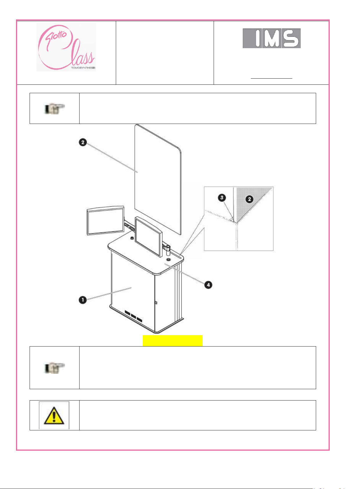
SERVICE AND
INSTALLATION
MANUAL
Via Sagittario 5 - 40037
Pontecchio Marconi (Bo)
Tel. ++39 051 846851
Fax. ++39 051 846856
www.imsitaly.com
pag 83 of 201
INFORMATION
Install the X-ray lead glass panel, with the word “Giotto” at the top and legible
from the side opposite the operator.
INFORMATION
The weight of the glass and the “mandatory” housing should be sufficient to
ensure the stability of the glass. However, the glass panel must be anchored
to the structure of the electric cabinet by four nylon screws.
CAUTION!
It is strictly forbidden to use the vertical X-ray unit (GANTRY) without the electric
cabinet panel.
Image under revision
After installing the panel, reposition and secure the electric cabinet panel.
M189_EN:Installation
Draft version_0.1 del 01/07/15

SERVICE AND
INSTALLATION
MANUAL
Via Sagittario 5 - 40037
Pontecchio Marconi (Bo)
Tel. ++39 051 846851
Fax. ++39 051 846856
www.imsitaly.com
pag 84 of 201
5.4.6. Removing the U.P.S. locking material
The upper and side part of the U.P.S. 1 may be locked (depending on the type of packaging) with a
plastic shim (or other material). This shim must be removed and stored for future moving of the
unit.
The various cables coming from the vertical X-ray unit (GANTRY) enter through the lower part of
the acquisition workstation (AWS) and are connected as shown in the figure.
M189_EN:Installation
Draft version_0.1 del 01/07/15
5.4.7. Connections between X-ray unit (Gantry) and Acquisition Work Station
(AWS)

SERVICE AND
INSTALLATION
MANUAL
Via Sagittario 5 - 40037
Pontecchio Marconi (Bo)
Tel. ++39 051 846851
Fax. ++39 051 846856
www.imsitaly.com
pag 85 of 201
5.4.8. Connection of High-Voltage cable
5.4.9. Installation and connection of the X-ray tube
5.4.10. Digital detector installation
5.4.11. Connection of the equipment to the power supply line
5.4.12. Electrical safety checks
5.4.13. Auxiliary signaling and safety connections
5.4.13.1. Connection of door contact and the warning lights
M189_EN:Installation
Draft version_0.1 del 01/07/15

SERVICE AND
INSTALLATION
MANUAL
Via Sagittario 5 - 40037
Pontecchio Marconi (Bo)
Tel. ++39 051 846851
Fax. ++39 051 846856
www.imsitaly.com
pag 86 of 201
M189_EN:Preliminary operating check
Draft version_0.1 del 01/07/15

SERVICE AND
INSTALLATION
MANUAL
Via Sagittario 5 - 40037
Pontecchio Marconi (Bo)
Tel. ++39 051 846851
Fax. ++39 051 846856
www.imsitaly.com
pag 87 of 201
6. Preliminary operating check
6.1. Checks before using the unit
Each equipment is tested at the factory before shipment. List of the tests performed:
• Mechanical alignment of moving parts.
• Mechanical calibration of transducers (potentiometers, encoder pressure sensors).
• Calibration of mechanical actuators software through PARAM TOMO software.
• X-ray tube software calibration.
• Calibrate touch screen software.
• Calibrate acquisition geometry.
• High voltage check with voltage divider and oscilloscope.
• Check of the anode current with oscilloscope.
• Check of the mAs with mAs meter.
• High voltage check with non-invasive instrument.
• (HVL) filtration check.
• Check of dose and dose rate.
• Check of X-ray field and light field collimation.
• Check of the electrical interface with digital detector.
• Check of the digital detector’s electrical noise level.
• Digital detector high voltage and lamp voltage check.
• Digital detector calibration check.
• Check of defective pixels and image artefacts.
• Check of the Potter-Bucky diaphragm and grid erasing.
• Check of the automatic exposure meter.
• Check of digital image acquisitions with “Raffaello” application software.
• Check image quality.
• Check of DVD mastering function.
• Network connection check (service and image transfer).
• Check of USB interface.
• Check that all the accessories are included in the shipment.
• Check electrical safety.
M189_EN:Preliminary operating check
Draft version_0.1 del 01/07/15

SERVICE AND
INSTALLATION
MANUAL
Via Sagittario 5 - 40037
Pontecchio Marconi (Bo)
Tel. ++39 051 846851
Fax. ++39 051 846856
www.imsitaly.com
pag 88 of 201
6.2. Initial start-up
The following must be checked the first time the system is started up:
- Emergency stop buttons.
- Surface of the compressors.
- Head rest surface.
- All parts in contact with patients.
- Breast support table.
- LCD display in the base of the equipment.
- Visual check of external parts to the equipment.
- Cable ducts.
- Mounting of the covers.
- Stability of the equipment.
- Tightness of fastening screws.
- Correct collimation of the X-ray field.
• Since the equipment was completely tested before shipment, the operations to be performed are
limited and the risk of damaging the equipment is very low.
• The connection cables between the control console and the stand are all different from one
another in order to avoid connection errors. All the boards have circuit breakers if the polarity of the
power supply is inverted.
Therefore, after the power supply check, the equipment can be switched ON.
Instruments: digital multimeter.
• With all cables connected and the equipment connected to the mains network and to the data
network:
• Main switch in OFF position. Apply power through the external electrical panel and check that the
voltage on
the input terminals of the main switch is correct. Also check the protective earth connection.
• Turn the main switch to the ON position. Verify that all the boards are powered, that LEDs are
illuminated and
fans are working, the message OFF STATE must appear after approximately 30 sec.
• Turn on the UPS switch. Wait a few seconds and verify that the UPS switches from battery to
mains power. (The UPS always uses the battery when turned ON and after a few seconds, if the
mains power is present, it switches to mains power. When operating on the battery, an intermittent
M189_EN:Preliminary operating check
Draft version_0.1 del 01/07/15

SERVICE AND
INSTALLATION
MANUAL
Via Sagittario 5 - 40037
Pontecchio Marconi (Bo)
Tel. ++39 051 846851
Fax. ++39 051 846856
www.imsitaly.com
pag 89 of 201
INFORMATION
For security reasons, the password occasionally changes.
(Consult the I.M.S. S.r.l. website http://www.imsitaly.com).
buzzer sounds; the switch to the mains network is recognized by the sound of a relay and by the
fact that the buzzer no longer sounds.
Check of digital image acquisitions with “Raffaello” application software.
Check of DVD mastering function.
Network connection check (service and image transfer).
Check of USB interface.
• Turn ON the workstation using the start button.
• Wait for the operating system to start then enter the password (Username: administrator).
• Turn ON the power circuits, green button located under the main switch. The main contactor of
the power circuitry must close and the equipment must perform the following self-diagnostic
operations within a few seconds:
Test collimator, change filter and lamp.
Filter wheel and lamp test.
Test the anti-scatter grid and potter movement.
Test movement of the X-ray tube.
Test the compressor.
• If all the tests are successful, the message AUTO will appear on the touch screen display and the
machine will be ready for use.
• Manually check the up/down movement of the column, the rotation both manual and programmed
and the tomo movement by performing the relative test (Consult the PARAM TOMO programme
guide for further details).
• If present, check the operation of the MAMMOBED and BIOPSY.
• Checking the correct collimation of the X-ray field. ( see the “Collimator “ paragraph in Section
13 -“Interventions on the unit”).
M189_EN:Preliminary operating check
Draft version_0.1 del 01/07/15

SERVICE AND
INSTALLATION
MANUAL
Via Sagittario 5 - 40037
Pontecchio Marconi (Bo)
Tel. ++39 051 846851
Fax. ++39 051 846856
www.imsitaly.com
pag 90 of 201
6.3. Troubleshooting before initial start-up
• After turning the main switch ON, the message “OFF STATE” does not appear on the control
console:
• Based on the type of alarm message, consult the alarm message section for further information.
The typical problems are:
No communication between the boards:
Check that the cables for the Ethernet network and for the equipment are inserted correctly.
No power to the electronic boards:
Check that all the boards have +24V logic, check the fuses, power packs and connection cables.
Emergency chain open:
Check the emergency stop buttons and verify the connections of the equipment’s real time bus
cables. The control console S856 board has two red LEDs that must be ON (one is for the
emergency stop button and one for the equipment’s fault chain).
If there is no power to the 24V logic, check the fuses in the control console and in the boards,
check the insulation tester, etc.
Data network connection error:
If the hospital data network is connected to the SERVICE port (connector JC56) instead of the
external port (connector JC26), communication between the electronic boards may not be
activated and the unit does not start. The error could also have consequences on the hospital data
network. Check the connections in the AWS workstation.
The UPS does not turn on:
The UPS battery must be recharged at least every 3 months if inactive. If the battery is completely
dead the UPS may not start correctly.
Check that the power switch on the front of the UPS is in the ON position.
The workstation doesn’t turn on:
Check for the presence of electrical power.
Verify that the power switch on the workstation is in the ON position.
Check that the control connector from the workstation to the control console keyboard is correctly
connected.
M189_EN:Preliminary operating check
Draft version_0.1 del 01/07/15

SERVICE AND
INSTALLATION
MANUAL
Via Sagittario 5 - 40037
Pontecchio Marconi (Bo)
Tel. ++39 051 846851
Fax. ++39 051 846856
www.imsitaly.com
pag 91 of 201
The LCD monitor doesn’t turn on:
Check the power supply voltage.
Check that the DVI cable is connected to the workstation.
WINDOWS doesn’t start:
Check that the mouse and keyboard are connected.
Use the USB pen drive attached to the equipment. Put it in the USB port located on the metal
frame of the control console and start the workstation; if Windows starts normally, this means that
the hard disk is corrupt.
The motors do not move:
Verify the compression force reading if the display on the base shows a compression force > 3 kg,
all the movements are inhibited and the compressor is free (without compression active). The
compression force reading mechanism needs to be checked (without compression force it must
always be 0 kg).
Verify the presence of the supply voltages: +24V power and 30V motors.
Vertical motor doesn’t move:
Verify that the 320V voltage is present in board S865, this voltage comes from the high voltage
inverter and there is a delay circuit to activate this voltage. This is due to the charging time of the
filter capacitors inside the inverter.
Errors with X-ray sequence in “M2” service mode:
Check the connection cables between the X-ray tube and the S866 board. All the X-ray functions
are managed by this board.
In normal operating mode with “Raffaello” application software the system is not ready for
X-ray emission (red or orange):
Wait at least 5 minutes.
Check the communication with the detector using the GMD SERVICE program.
Check with the ParamTomo program, under the menu Diagnostic->Detector->Digital IOs, that
the PLATE_
SYNC signal pulses correctly 2.8 sec. (MAMMO) / 1 sec. (TOMO). For versions of the “Raffaello”
application prior to 2.2.x.x. check that the PLATE_SYNC signal is pulsing correctly 3.5 sec.
(MAMMO) / 1 sec. (TOMO).
M189_EN:Preliminary operating check
Draft version_0.1 del 01/07/15

SERVICE AND
INSTALLATION
MANUAL
Via Sagittario 5 - 40037
Pontecchio Marconi (Bo)
Tel. ++39 051 846851
Fax. ++39 051 846856
www.imsitaly.com
pag 92 of 201
CAUTION!
To perform mammograms on patients the quality checks must be carried out by
qualified personnel and must be within the acceptance limits. I.M.S. S.r.l. cannot
guarantee the clinical result if all these checks are not performed.
Verify the power supply voltage for the detector, board S801.
Check the status LEDs on board S878.
6.4. Quality checks before clinical application
After checking that all the equipment’s functions are ON and operational, the radiological
parameters, image quality and compression values, collimation, etc. must be checked using
suitable instruments that are calibrated and in good working order before the clinical examination
can be performed on the patient.
These are standard quality checks for mammography equipment. Refer to the “Quality assessment
of the Flat-Field image” Section in this manual for a brief guide or refer to the digital mammography
quality protocols (vary from country to country).
These checks must be done in accordance with local laws.
To evaluate Flat-Field images, or for problems relating to the correct operation of the X-ray tube or
the digital detector, refer to the specific chapter.
6.5. Connection to the DICOM ntework
The equipment can be connected to the DICOM network through the “Raffaello” application
software in order to exchange images and clinical data.
Refer to the DICOM CONFORMANCE STATEMENT for more information on the available
functions.
To configure the equipment for a DICOM connection, some parameters in “Raffaello” application
software and the equipment’s AWS acquisition workstation normally need to be set.
Read the of “Raffaello” application software guide for further details.
M189_EN:Preliminary operating check
Draft version_0.1 del 01/07/15

SERVICE AND
INSTALLATION
MANUAL
Via Sagittario 5 - 40037
Pontecchio Marconi (Bo)
Tel. ++39 051 846851
Fax. ++39 051 846856
www.imsitaly.com
pag 93 of 201
6.6. Operator instructions
To complete the commissioning of the equipment the operators, radiologists and technicians need
to be trained on its use.
For this, the following must be done:
• Explain the operator’s manual.
• Power ON and power OFF procedure.
• Procedure to identify an alarm on the equipment and how to resolve it.
• Both manual and automatic movements for the equipment.
• Installation of accessories and use.
• Use of the “Raffaello” application software.
• Daily quality checks.
• Breast phantom and mammography simulation and technical explanations of radiographic work
techniques.
• Use of the BIOPSY.
• Use of the MAMMOBED.
• Transmission of the images to PACS and RWS.
• How to manipulate images for diagnostic use.
• Printing of images and image transfer to CD DICOM.
M189_EN:Preliminary operating check
Draft version_0.1 del 01/07/15

SERVICE AND
INSTALLATION
MANUAL
Via Sagittario 5 - 40037
Pontecchio Marconi (Bo)
Tel. ++39 051 846851
Fax. ++39 051 846856
www.imsitaly.com
pag 94 of 201
7. Method of use
7.1. Equipment
7.1.1. Preliminary operations before switching on
7.1.1.1. Cleaning
see Secton 1 - “Safety”.
7.1.2. Switching on/Operating
The X-ray unit, the operator control console and the UPS are switched on separately by means of
their own switches.
The monitors can be switched off separately or using the main switch.
1) On/Off switch for the touchscreen panel
2) On/Off switch for the TFT monitor
3) On/Off switch for the workstation
4) Main On/Off switch
5) On/Off switch On/Off switch for insertion circuits
6) On/Off switch for the UPS
M189_EN:Method of use
Draft version_0.1 del 01/07/15
Image under revision

SERVICE AND
INSTALLATION
MANUAL
Via Sagittario 5 - 40037
Pontecchio Marconi (Bo)
Tel. ++39 051 846851
Fax. ++39 051 846856
www.imsitaly.com
pag 95 of 201
CAUTION
Limited image quality caused by incorrect use.
The equipment’s detector needs to warm up for about 15 minutes before
images can be generated.
CAUTION
Limited image quality caused by incorrect use.
If the software indicates that a calibration has gone beyond its foreseen
interval, optimal image quality cannot be guaranteed.
Contact the Support Service as soon as possible.
Starting the system when off
If the equipment was switched off using the master switch, the entire system needs to be restarted.
Switch on the master switch located in the room.
Press the On switch on the control unit to start the equipment.
– The internal control system automatically performs a functional check of the equipment.
Switch on the UPS.
Switch on the workstation, the touchscreen panel and the monitor of the acquisition
workstation.
– The workstation switches on.
Log into the workstation.
Let the equipment warm up for about 30 minutes before performing an optimal image quality
test or a calibration.
Login with a username and password is required if access protection was set in the user
management section.
For further information refer to Section 9 - “User management and access protection” of the
GIOTTO CLASS Operator Manual.
7.1.1. Calibration
The detector settings may be modified by outside factors (for example: changes in temperature,
humidity and vibrations). This is why the detector must be regularly calibration.
The calibration procedures must be performed by IMS S.r.l. technical personnel at the frequency
indicated by the “Raffaello” application software”.
7.1.1.1. Daily check
Prima di iniziare la sessione di esami è richiesta una verifica della qualità di immagine
mediante una procedura automatizzata.
see Section 7.11 - “Quality Control Procedures”.
M189_EN:Method of use
Draft version_0.1 del 01/07/15

SERVICE AND
INSTALLATION
MANUAL
Via Sagittario 5 - 40037
Pontecchio Marconi (Bo)
Tel. ++39 051 846851
Fax. ++39 051 846856
www.imsitaly.com
pag 96 of 201
WARNING
Risk of injury due to moving parts on the equipment.
The equipment’s motorized movements can crush or trap parts of the body.
Make sure that the patient is positioned correctly. Be aware of possible spots on
the equipment that can cause injuries or crushing.
see Section 1 - “Safety”.
In case of emergency, immediately press one of the red emergency stop buttons
located on the vertical X-ray unit and on the acquisition unit
see Section 1 - “Safety”.
Before activating the isocentric functions, make sure that the patient, staff and
third parties are not exposed to risks during the movement of the mobile arm.
WARNING
Incorrectly recorded patient data can lead to incorrect results.
Incorrect diagnosis or unnecessary exposure to radiation if the X-ray needs to
be repeated!
Before every exam, check that the patient corresponds to the data and to the
procedure loaded into the system.
7.1.2. Method for basic use
7.1.2.1. Safety during the examination
M189_EN:Method of use
Draft version_0.1 del 01/07/15

SERVICE AND
INSTALLATION
MANUAL
Via Sagittario 5 - 40037
Pontecchio Marconi (Bo)
Tel. ++39 051 846851
Fax. ++39 051 846856
www.imsitaly.com
pag 97 of 201
7.1.2.2. Performing the examination
How to perform the exam:
On the acquisition workstation
1) Open a new study using the appropriate procedure.
see in the present section at the paragraph “Patient Registration”.
2) Select the exposure mode (Auto/Man) and, if necessary, manually set the exposure parameters.
esposizione
see in the present section at the paragraph “Exposure data setting”.
3) Select the side of the first projection (if an exam protocol has been configured, the first
projection will be automatically proposed).
see in the present section at the paragraph “Manual setting the projections”.
On the x-ray unit
4) Mount a suitable compression paddle for the exam.
see in the present section at the paragraph “Compressor Paddle”.
5) Eventually apply the face protector.
see in the present section at the paragraph “Face protection”.
6) Set the gantry to the desired projection angle.
see in the present section at the paragraph “Gantry position setting”.
7) Set the gantry to the appropriate height and tilt angle.
see in the present section at the paragraphs “Gantry height adjustment” and “Gantry tilt angle
adjustment”.
8) Place the breast to be examined on the breast support surface based on the view selected from
the acquisition workstation.
9) Lower the compression paddle using the foot switch or the handle.
see in the present section at the paragraph “Compression using the foot-switch”.
10) Make sure that the breast is correctly compressed. Use the lighting to ensure that the
compression does not cause folds in the skin. If possible, the profile of the nipple should be visible.
11) Make sure that only the breast to be examined is in the irradiation field.
M189_EN:Method of use
Draft version_0.1 del 01/07/15

SERVICE AND
INSTALLATION
MANUAL
Via Sagittario 5 - 40037
Pontecchio Marconi (Bo)
Tel. ++39 051 846851
Fax. ++39 051 846856
www.imsitaly.com
pag 98 of 201
CAUTION
Unnecessary exposure to radiation if the X-ray needs to be repeated.
If the button is released before the acoustic signal finishes, the exposure will
be interrupted and the image will be underexposed.
On the acquisition workstation
12) Check the exposure parameters.
13) Wait for the X-ray button to light (green) before beginning the X-ray.
14) Press and hold the X-ray button on the control unit for the entire time you hear the acoustic
signal.
– During the X-ray, the radiation symbol will appear on all the displays (black clover with
yellow background).
– The irradiation begins and the first exam image is created.
15) The irradiation indicator must remain on only when the start X-ray button is pressed. Comply
with the measures regarding radiation protection.
16) After the image has been created, it will be displayed in the appropriate area.
17) Make sure that the breast is automatically or manually decompressed after the X-ray.
18) Check the image’s quality.
If necessary, cancel the image and repeat the operations from 10 to 20.
refer to the “Delete images” paragraph of this section.
19) Repeat the operations from 2 to 18 until all the projections have been performed.
20) Finish the exam.
refer to the “Concluding the exam” paragraph of this section.
The digital X-ray is automatically displayed on the TFT monitor about 3 - 5 s after the end of the
entire acquisition. The AWS P.C. needs this time to acquire the image, apply the standard
corrections and to adapt the image to the mammography standard. During this stage, the image is
adapted to improve the aspects when viewed by the technician for the first time. In the case of
tomosynthesis or combo acquisition, the reconstructed volumetric image will instead be available
about 1-2 minutes later depending on the volume dimension.
M189_EN:Method of use
Draft version_0.1 del 01/07/15

SERVICE AND
INSTALLATION
MANUAL
Via Sagittario 5 - 40037
Pontecchio Marconi (Bo)
Tel. ++39 051 846851
Fax. ++39 051 846856
www.imsitaly.com
pag 99 of 201
7.1.3. Compressor Paddle
Image under review
Insert the compression paddle with the guide into the compression housing unit by making a
left to right movement.
– The compression paddle automatically locks.
Keep lever 1 pressed.
Slide the compression paddle out laterally by removing it from the housing guide 2.
M189_EN:Method of use
Draft version_0.1 del 01/07/15
Images under review

SERVICE AND
INSTALLATION
MANUAL
Via Sagittario 5 - 40037
Pontecchio Marconi (Bo)
Tel. ++39 051 846851
Fax. ++39 051 846856
www.imsitaly.com
pag 100 of 201
7.1.4. Geometrical Magnification device
Images under review
The magnification device provides a 1.8 magnification factor.
Using the side handles, insert the magnification device into the support.
Grasp the handles on the side of the magnification device and pull towards yourself to
remove it from the support.
For selective spot projection, use a compression paddle for zooming or for spot projections
and zooming.
M189_EN:Method of use
Draft version_0.1 del 01/07/15
Images under review
 Loading...