

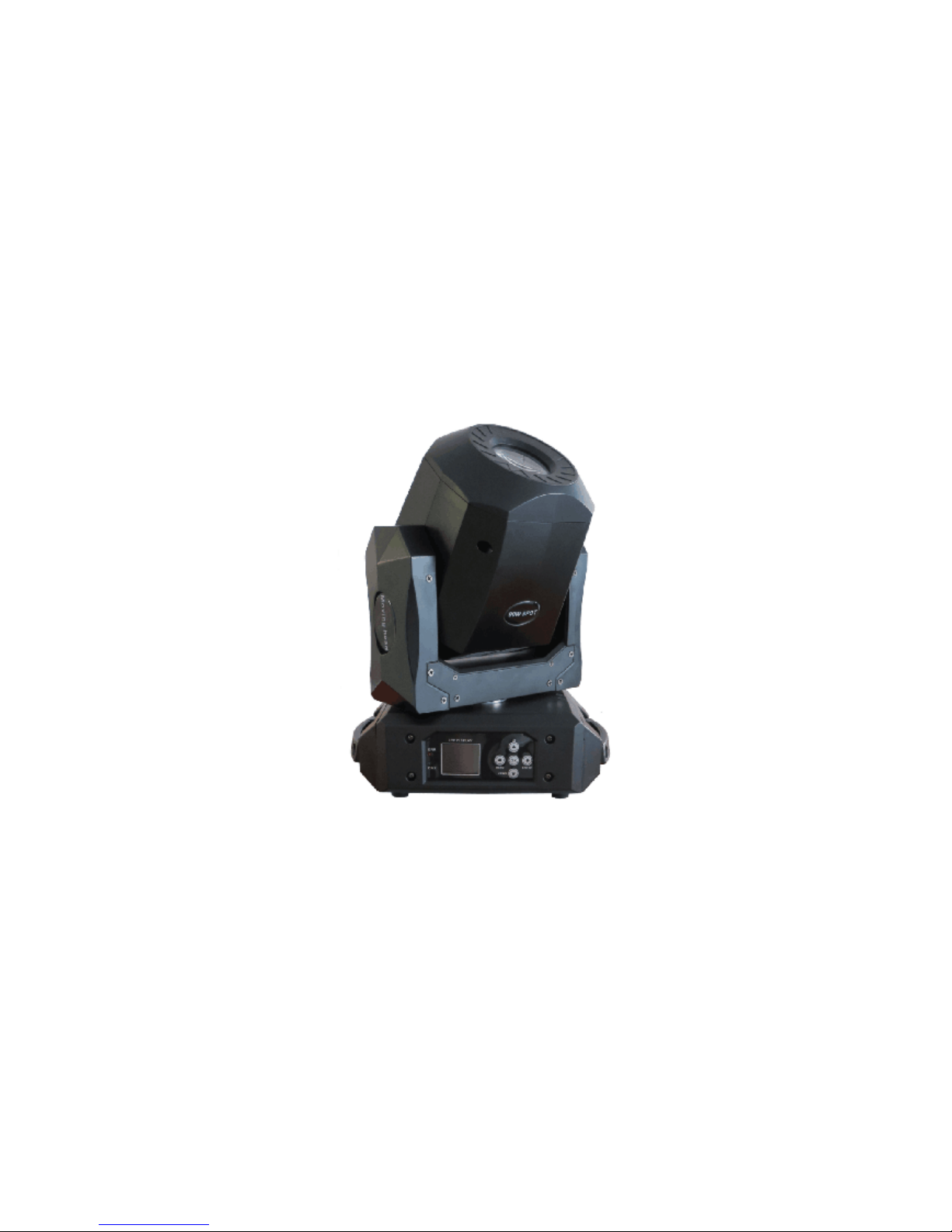
IM-MH90S
90W LED SPOT MOVING HEAD
USER MANUAL
Ver1.0

Table of contents
1. Preface ················································· 2
1.1 Packing list ········································ 2
1.2 Unpacking instructions ····················· 2
1.3 AC Power········································· 2
1.4 Safety instructions ········································ 2
2. Introduction ············································ 3
2.1 Features ·········································· 3
2.2 DMX channel ·································· 3
3. Setup ····················································· 4
3.1 Fuse replacement ································ 4
3.2 Fixture linking ································ 4
3.3 3-Pin to 5-Pin conversion chart ······················· 4
3.4 Setting up a DMX serial data link ····················· 4
3.5 Master/Slave fixture linking ···························· 5
3.6 orientation ··················································· 5
4. Operating instructions ····························· 5
4.1 Description of operation panel ················· 5
4.2 Menu map ······································· 5
4.3 DMX channel values ························ 7
5. Technical specifications ························· 10
Please read these instructions, it includes important information about the
installation, usage and maintenance of this product.
Warning! Verify that the voltage select switch on your unit matches the line
voltage applied. Damage to your fixture may result if the line voltage applied
does not match the voltage indicated on the voltage selector switch. All fixtures
must be connected to circuits with a suitable Earth ground.
1. Preface
1.1 Packing list
Product name quantity
moving head light 1 pcs
Power -line 1 base
User manual 1pcs
1.2 Unpacking instructions
On receiving a fixture, carefully unpack the carton, check the contents to
ensure that all parts are presented, and have been received in a good
condition. Notify the shipper immediately and retain packing material for
inspection if any parts appear damaged from shipping or the carton itself
shows, sign of mishandling. Save the carton and all packing materials. In the
event that a fixture must be returned to the factory, it is important that the
fixture should be returned in original factory box and packing.
1.3 AC Power
To determine the power requirements for a particular fixture, see the label
affixed to the back plate of the fixture or referred to the fixtures specification
chart. A fixture listed current rating is its average current draw under normal
conditions. All fixtures must be directly powered off a switched circuit and
cannot be run off a rheostat (variable resistor) or dimmer circuit, even if the
rheostat or dimmer source voltage matches the fixtures requirement. Check
the fixture or device carefully to make sure that if a voltage selection switch
exists that it is set to the correct line voltage you will use.
1.4 Safety instructions
Please keep this user guide for future consultation. If you sell the unit to
another user, be sure that they also receive this instruction booklet.
Always make sure that you are connecting to the proper voltage, and that the

line voltage you are connecting to is not higher than that stated on the decal or
rear panel of the fixture.
Before the first time to use it, Please check whether the damage in transit, if
happen damages in transit, please do not use this lamp, and please asap
contact distributors or manufacturers.
Please don't install the lamp in the ordinary combustible material on the
surface. Lamp should be installed in the well ventilated place, and the distance
of the wall to keep it over 10 cm, at the same time, please check the fan hole
was clear.
Do not use lamp direct project in flammable objects, lamp and the radiation
of the distance between the objects please keep it over 12 m.
Do not use direct lamp project light source , to avoid damage the eyes.
Before installation, please make sure your use power supply voltage and
marked voltage
Note: before any install, maintain and clean lamp, please confirm cut off the
power supply.
2. Introduction
2.1 Features
*Light source:1pcs 90W white LED
*Electronic dimmer 0~100%
*Fan Cooling /Forced convection
*Pan movement:540°
*Tilt movement:270°
*Pan/Tilt resolution:8-16bit
*Prism rotating 3-facet prism
*Focus:linear focus from close to far
*1 fixed gobo wheel: 8gobos plus blank
*1 rotated gobo wheel: 6gobos plus blank,gobo rotating 360°
*1 color wheel:7colors plus white
*Strobe:0-16Hz, from slow to fast, adjusting
*Control mode:Auto, sound active , DMX512
*DMX channel:15CH
* LCD display
2.2 DMX channel
3. Setup
Disconnect the power cord before replacing a fuse and always replace with the
same type fuse.
3.1 Fuse replacement
With a flat head screwdriver wedge the fuse hold out of its housing. Remove

the damaged fuse from its holder and replace with exact same type fuse. Insert
the fuse holder back in its place and reconnect power.
3.2 Fixture linking
You will need a serial data link to run light show of one or more fixtures using a
DMX-512 controller or to run synchronized on two or more fixtures set to a
master/slave operating mode. The combined number of channels required by
all the fixtures on a serial data link determines the number of fixtures the data
link can support.
3.3 3-Pin to 5-Pin conversion chart
Note! If you use a controller with a 5 pin DMX output connector. You will need
to use a 5pin to 3 pin as apter
CHAUVET Model No: DMX5M. Or DMX 5F
The chart below details a proper cable conversion:
3.4 Setting up a DMX serial data link
At first link the first light and DMX control through XLR-connection signal cable,
then connect the light in series, as the follow:
3.5 Master/Slave fixture linking
1. Connect the (male) 3 pin connector side of the DMX cable to the output
(female) 3pin connector of the first fixture.
2. Connect the end of the cable coming from the first fixture which will have a
(female) 3 pin connector to the input connector of the next fixture consisting of
a (male) 3 pin connector. Then, proceed to connect from the output as stated
above to the input of the following fixture and so on.
3.6 orientations
This fixture may be mounted in any position provided there is adequate room
for ventilation.

4. Operating instructions
4.1 Description of operation panel
4.2 Menu map
Setting
running mode
Controller
sound
performance 1
performance 2
performance 3
performance 4
random
Address 1-512
DMX
15CH
sound sensitivity 1-99
Pan Reverse ON/OFF
Tilt Reverse ON/OFF
Pan/Tilt exchange swap
ON/OFF
coding mask ON/OFF
Signal timeout Blackout /keep
Screen save ON/OFF
color liner ON/OFF
reset Confirm
Manual mode
dimmer 0-255
strobe 0-255
pan 0-255
pan fine 0-255
up
menu enter menu
down
DMX
ERR

tilt 0-255
tilt fine 0-255
pan/tilt speed 0-255
color 0-255
gobo 0-255
gobo2 0-255
gobo2 rotate 0-255
focus 0-255
prism rotate 0-255
auto 0-255
reset >
offset value
offset value
pan offset (-128) - (+127)
tilt offset (-128) - (+127)
color wheel offset (-128) - (+127)
gobo wheel offset (-128) - (+127)
gobo wheel2 offset (-128) - (+127)
focus offset (-128) - (+127)
Advance setting
language switch Confirm
The screen upside
down
Confirm
Time to reset Confirm
Protect the
temperature
0-120
Hardware
information
color wheel Hoare X
gobo wheel Hoare X
gobo wheel2 Hoare X
focus Hoare X
pan coding mask XX
pan route XXXXX
tilt coding mask XX
tilt route XXXXX
System information
Version XXXXXXXXXX
Use time of fixture XXXXX
Turn on time XXXXX
temperature XXX
When the Temperature resistance has problem, the screen will
have the following tips:
Thermistor Open
Thermistor Short
Thermistor Hot

4.3DMX channels
15CH
15
channel
Function
channel
value
description
1 dimmer 0-255 from dark to bright
2 strobe
0-10 no strobe
11-255
from slow to fast strobe
3
pan
0-255 pan
4
pan fine
0-255 pan 16 bit
5
tilt
0-255
tilt
6
tilt fine
0-255
tilt 16 bit
7
pan tilt speed 0-255 pan tilt speed slow
8 color
0-9 white
10-19 white+color 1
20-29 color 1
30-39 color 1+color 2
40-49 color 2
50-59 color 2+color 3
60-69 color 3
70-79 color 3+color 4
80-89 color 4
90-99 color 4+color 5
100-109
color 5
110-119
color 5+color 6
120-129
color 6
130-139
color 6+color 7
140-149
color 7
150-159
color 7+white
160-255
color anticlockwise from slow to fast
water
9
fix gobo wheel
0-9 white
10-19 gobo 1
20-29 gobo 2
30-39 gobo 3
40-49 gobo 4
50-59 gobo 5
60-69 gobo 6
70-79 gobo 7
80-89 gobo 8
90-99 white

9
fix gobo wheel
100-109
gobo 1 shake
110-119
gobo 2 shake
120-129
gobo 3 shake
130-139
gobo 4 shake
140-149
gobo 5 shake
150-159
gobo 6 shake
160-169
gobo 7 shake
170-179
gobo 8 shake
180-214
gobo clockwise from fast to slow
215-219
stop
220-255
gobo anticlockwise from slow to fast
10 gobo 2
0-9 white
10-19 rotated gobo 1
20-29 rotated gobo 2
30-39 rotated gobo 3
40-49 rotated gobo 4
50-59 rotated gobo 5
60-69 rotated gobo 6
70-79 white shake
80-89 rotated gobo 1 shake
90-99 rotated gobo 2 shake
100-109
rotated gobo 3 shake
110-119
rotated gobo 4 shake
120-129
rotated gobo 5 shake
130-139
rotated gobo 6 shake
140-194
rotated gobo clockwise from
195-199
stop
200-255 rotated gobo anticlockwise from
11 gobo 2 rotated
0-127 gobo degree
128-190
gobo clockwise from fast to slow
191-192
stop
193-255
gobo anticlockwise from slow to fast
12 focus 0-255 focus
13 prism rotated
0-127 invalid
128-136
valid
137-255 prism from slow to fast rotated
14 Macro Function
0-255 from dark to bright
0-5 invalid
6-55 Perform 1
56-105
Perform 2

106-155
Perform 3
156-205
Perform 4
206-255
random model
15 reset
0-25 invalid
26-76 Motor reset
77-127
XY reset
128-255
Whole reset
5.Technical specifications
Voltage
AC100-240v 50/60Hz
LED
90W LED
Color wheel
7 colors+open
Gobo wheel
1 fixed gobo wheel: 8gobos plus blank
1 rotated gobo wheel: 6gobos plus blank,gobo
rotating 360°
Max temperature
104°F(40°C)
Data input/output
3pin XLR-connection、anode socket
Outside size
270*190*390mm
N.W
9kg
 Loading...