

IMR IX 176
Ambient Gas Detectors
IMR
ENVIRONMENTAL EQUIPMENT, INC.
3634 Central Ave.
St. Petersburg, FL 33782
Phone: 727-328-2818
E-Mail: Info@imrusa.com

1 | P a g e IMR IX 176
IMR ENVIRONMENTAL EQUIPMENT, INC.

2 | P a g e IMR IX 176
Contents
NOTICE: ..................................................................................................................................................... 3
INTRODUCTION ......................................................................................................................................... 3
1. FEATURES AND SPECIFICATIONS ....................................................................................................... 4
1.1. FEATURES .................................................................................................................................. 4
1.2. SPECIFICATIONS ........................................................................................................................ 4
2. STRUCTURE AND FUNCTION ............................................................................................................. 4
2.1. STRUCTRUE ................................................................................................................................ 4
2.2. SCREEN DISPLAY CONTENT ........................................................................................................ 5
2.3. BUTTONS FUNCTIONS ............................................................................................................... 5
3. OPERATING INSTRUCTIONS .............................................................................................................. 6
3.1 MENUE OPTIONS....................................................................................................................... 7
4. CALIBRATION AND ALARM LEVELS ADJUSTMENTS ........................................................................ 10
5. BATTERY CHARGING ....................................................................................................................... 12
6. DATA UPLOADING ........................................................................................................................... 13
7. USING AND REPLACING OF SENSOR ............................................................................................... 13
8. USING THE ACCESSORIES ................................................................................................................ 13
9. TROUBLESHOOTING GUIDE ............................................................................................................ 14
OPERATION NOTICES .............................................................................................................................. 15
IMR ENVIRONMENTAL EQUIPMENT, INC.

3 | P a g e IMR IX 176
NOTICE:
To avoid personal safety injury, Instrument damage and potential dangerous accident; do not use
the product before reading this manual.
INTRODUCTION
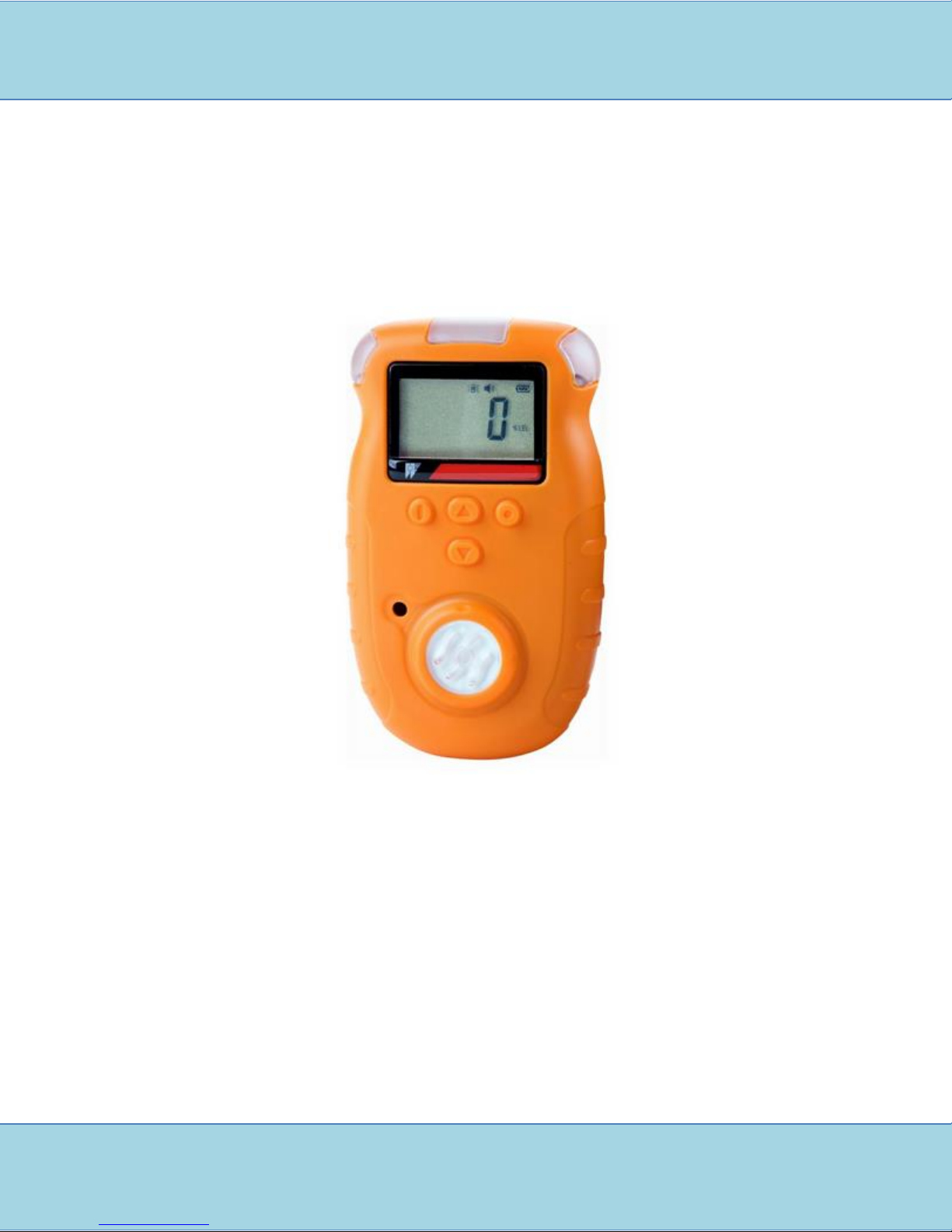
IX176 portable single gas detector (intrinsically safe) can make continuous detection to combustible
and toxic gases. It is suitable for combustible and toxic gas leakage detection in underground pipe or
mines, and keeps the workers safe, prevents the facilities from being destroyed. The detector,
adopting excellent-quality sensor, makes detection in the way of natural diffusion. It has good
sensitivity and reproducibility. The detector adopts embedded MCU controller, easy to operate.
The shell adopts special high strength material and anti-smooth rubber, with the characters of waterproof and dust-proof.
IMR ENVIRONMENTAL EQUIPMENT, INC.
4 | P a g e IMR IX 176
1. FEATURES AND SPECIFICATIONS
1.1. FEATURES
IX176 portable single gas detector (intrinsically safe) can make continuous detection to
combustible and toxic gases.
It is suitable for combustible and toxic gas leakage detection in underground pipe or
mines, and keeps the workers safe, prevents the facilities from being destroyed.
The detector, adopting excellent-quality sensor, makes detection in the way of natural
diffusion.
It has good sensitivity and reproducibility.
The detector adopts embedded MCU controller, easy to operate.
The shell adopts special high strength material and anti-smooth rubber, with the
characters of water-proof and dust-proof.
1.2. SPECIFICATIONS
Target gas: LEL, O2, toxic gases.
Accuracy: ≤±5% F.S.
Response time: T<30s
Indication: LCD indicates the time and state
Audible, visual and vibration alarm signals
Working temperature: -40℃~70℃ (for combustible gas)
-20℃~50℃ (for toxic gas)
Working humidity: <95%RH
IP rating: IP65
Power supply: DC3.7V, 1300mAh Li-ion battery
Communication: RS232/USB
Continuously working time: ≥10h continuously (without alarming)
Combustible gas: ≮ 8h continuously
Toxic gas: ≥300h continuously
Charging time: 4~6 hours
Sensor life: 2 years
Dimension and weight: 104.0mm×60.8mm×30.5mm about 125g
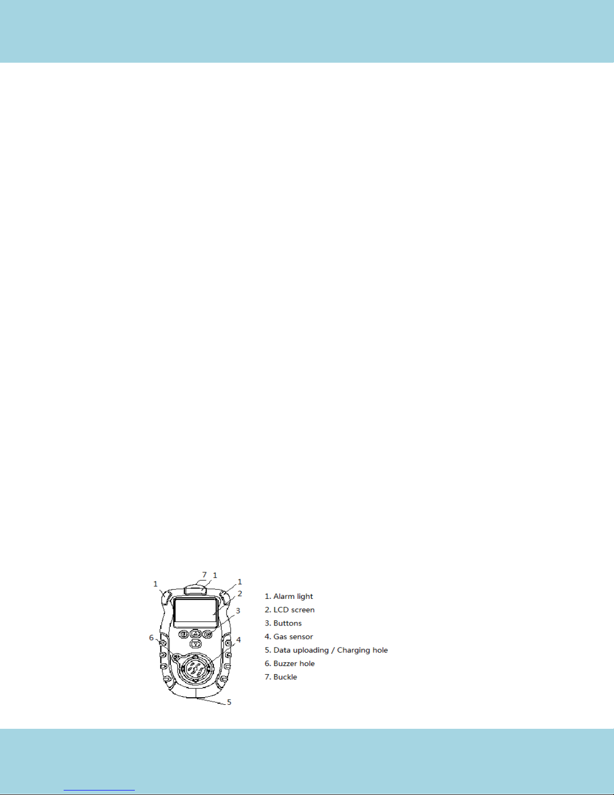
2. STRUCTURE AND FUNCTION
2.1. STRUCTRUE
IMR ENVIRONMENTAL EQUIPMENT, INC.

5 | P a g e IMR IX 176
2.2. SCREEN DISPLAY CONTENT
Note: Data uploading function is only available only when the product you bought
has this function.
2.3. BUTTONS FUNCTIONS
IMR ENVIRONMENTAL EQUIPMENT, INC.

6 | P a g e IMR IX 176
Note: ① Password is needed when this operation does.
② Only the detector for toxic gas has this function.
③ Only O2 sensor has maximum and minimum level.
3. OPERATING INSTRUCTIONS
Turn on the detector
Hold for 3 seconds and the detector will be turned on. Then, the detector begins a
self-test as follows:
o The LCD displays all of the screen elements.
o Alarm function: audible signal, visual signal and vibration signal.
o Software version number:
Date and Time
Preset Low Alarm and High Alarm value:
STEL and TWA values
Note: The above pictures can only appear for toxic gases.
Self-test and warm up
If the detector passes the self-test, it enters into a short-time countdown to warm up.
After that it enters normal operating mode. The LCD displays the ambient gas reading
Note: If the self-test fails, the LCD will display relative information. For details, please refer to the
Time Error Alarming and Memorizer Alarming in the Alarming Status. If count down occurs when
there is not fault, the device will choose a proper time of 3-30s according to the different sensors.
IMR ENVIRONMENTAL EQUIPMENT, INC.

7 | P a g e IMR IX 176
Turn off the detector
Keep holding . The screen will display “OFF” and the buzzer gives beep sound. After 3
seconds, when it displays the following figure on the screen, loosen the “ ”key. The
detector is turned off.
Note: When the detector is not in the detecting status, press continuously till it returns to the
detection mode.
3.1 MENUE OPTIONS
The menu options include:
Setup of date and time
On/Off of the vibration
On/Off of the key sound
Mode of communications ①
Setup of the password
Note: ① this function is available only when the product you bought has the function of data
communications.
In the mode of normal detection status, hold and simultaneously until the screen displays as
following figure for 1 second, and then release the buttons. It enters into the menu.
Press or to choose the option you need. The following is
the indication picture of each option.
IMR ENVIRONMENTAL EQUIPMENT, INC.

8 | P a g e IMR IX 176
Note: ① this function can be available only when the product you
bought has the function of data communication.
After entering into each item, press or to change options, press to confirm, press to
exit without saving. The following is the meaning of each options:
Alarming indication
The following table describes detector alarms and shows how the
LCD looks for each alarm:
IMR ENVIRONMENTAL EQUIPMENT, INC.

9 | P a g e IMR IX 176
Note: ① It can vibrate only when the vibration item is open.
② It is only available for combustible gas.
IMR ENVIRONMENTAL EQUIPMENT, INC.

10 | P a g e IMR IX 176
When alarming continuously, you can press to turn off the audible alarm and vibration, while the
and are flashing.
To check the device status, Press and , the LCD will
display Temperature, time, STEL & TWA levels①, maxium level and
minimum level②.
Note: ① It is only available for toxic gases.
② Only O2 sensor has maximum and minimum level.
Automatic zero calibration
In the clean air, if the detecting value is not 0, choose this function to
make the zero calibration. In the mode of detection, press both and for 1 second,
when it displays “please input password’, then release the two buttons. After that input
the password to calibrate the zero point. The detector will display the following
information in turns:
Note: It is calibrated the concentration of oxygen in clean air for O2
sensor, that is 20.9%VOL.
Warning: This operation should be carried out in the clean air.
Otherwise the accuracy of the detector will be affected differently according to the
different gas concentration in the air.
4. CALIBRATION AND ALARM LEVELS ADJUSTMENTS
If you need to re-calibrate the detector or adjust the alarm levels, please follow the following steps:
Enter into the calibration and alarming level adjustment mode: When the device is close,
press amd and hold for 5 seconds, the detector begins self-test. If the self-test passes,
then after a short time,it indicates inputing the password as showed in the following
chart:
IMR ENVIRONMENTAL EQUIPMENT, INC.

11 | P a g e IMR IX 176
Only the password is correct can the detector enters into the zero calibration mode.
Note: As all the parameters of this mode may endanger the safety of the operator, so please make
the operation carefully Within 10s after indicating inputting the password, if there is no
operation or the password is wrong, the detector will be deactivated. So please input the
right password in time.
Zero calibration
In this mode, the detector will display a figure it detected as shown in the following chart:
At this time, if is pressed or no operation within 1 minute, the detector will accept the
present concentration as the zero point, and then enters into the mode of calibration
point set up. And press , it jumps over the calibration step to enter into the mode of
alarming level set up, with reference to the 5 and 6 items.
Warning: This operation should be carried out in the clean air. Otherwise the accuracy of the
detector will be affected differently according to the different gas concentration in the air.
When entering into the next mode, if it displays E, which means the air is not clean, or
the sensor is destroyed. So please choose another adjustment place or replace the
sensor.
Calibration point adjustment
In this mode, the screen displays a set of flickering figures. Press or to modify
this figure. This figure is the standard sample gas level with which the operator needs to
calibrate the detector, as shown in the following chart:
At this time, if is pressed or no operation within 1 minute, the
detecor will accept the present concentration as the calibration gas
concentration, and then enters into the mode of calibration point set
Calibration point adjustment
In this mode, the detector displays a concentration value detected as shown in the
following chart:
IMR ENVIRONMENTAL EQUIPMENT, INC.

12 | P a g e IMR IX 176
At this time, please cover the gas response hole with the calibration cap, open the gas
valve to adjust the flux as 120mL/min. Within 30 seconds, if the detector detects the
calibration gas, the detector will start up the calibration date analysis procedure by itself.
And the detector will automatically adjust the conversion arithmetic till all the standard
gas complete the response. Then the detector saves the
best arithmetic and complete the calibration. After that it enters into
the L-alarm set up.
Note: In this mode, please avoid touching any buttons, otherwise the accuracy will be effected
badly. If the detector indication figure can’t reach half the calibration figure within 30s, or
the gas concentration is beyond the maximum drift range of the sensor, the E ico will
light, which means the gas is not proper for calibration or the sensor is destroyed. Please
replace the gas or the sensor. The calibration of O2 sensor will jump over process two
previous steps
Set up of L-alarm
In this mode, the L-alarm level can be adjusted, and the screen displays as the following
chart, with the figure flickering. Press or to adjust the flickering figure according
to your need, and then press to complete the set up. After this the instrument goes
into the H-alarm setup.
Set up of H-alarm
In this mode, the H-alarm level can be adjusted, and the screen displays as the following
chart, with the figure flickering. Press or to adjust the flickering figure according
to your need, and then press to complete the set up. After that the detector will
automatically turn off.
5. BATTERY CHARGING
When the power supply is not enough or the detector cannot work normally due to the low voltage,
please charge in time.
IMR ENVIRONMENTAL EQUIPMENT, INC.

13 | P a g e IMR IX 176
Note: You can’t activate the detector when is being charged in the status of power off. In order to
avoid fire or explosion, please do not charge the detector when it is working in the spot.
Please try not to charge when the detector is power on, otherwise the charge speed
will be affected.
6. DATA UPLOADING
Connect the detector to PC through the USB cable. Then open the software for uploading the
detection record.
Note: This function can be available only when the product you
bought has the function of data communication.
7. USING AND REPLACING OF SENSOR
As the sensor of the detector is modularized, so please pay attention to the life of the sensor.
When it is overdue, please replace it. Every half year you need to calibrate the sensor in order to
guarantee the accuracy of the detector.
The sensor replacement shoul be carried out by the seller or the local repairing department. If
there is no distributor or repairing department, please replace the sensor after you get permission
from our company. The sensor should be replaced with the same modularized sensor
supplied by our company.
8. USING THE ACCESSORIES
For the user easy or bring, we equip buckle, crocodile buckle and flying ring with the detector. If you
need the above accessories, you can fix them on the back shell of the detector with the screw. If you
mainly use the buckle, please take out the crocodile buckle,and then fix the buckle.
IMR ENVIRONMENTAL EQUIPMENT, INC.

14 | P a g e IMR IX 176
9. TROUBLESHOOTING GUIDE
IMR ENVIRONMENTAL EQUIPMENT, INC.

15 | P a g e IMR IX 176
OPERATION NOTICES
1. Prevent the detector from falling down high places or serious vibration.
2. When there is interferential high-concentration gas, the detector may not work normally.
3. Please operate and handle in strict accordance with the introduction, otherwise the result
may be incorrect or you may destroy the detector.
4. The detector should not be stored or used under the circumstance with caustic gas (such as
Cl2), or be use or stored under the other rigorous circumstances (including excessive high
and low temperature, higher humidity, electromagnetic field and strong sunlight).
5. After long-term use, if there is dust on the surface of the detector, please clean it lightly with
clean soft cloth, instead of caustic impregnant or hard things. Otherwise, the surface of the
machine may be destroyed.
6. To assure the testing accuracy, the detector should be calibrated termly, and the calibration
period should not more than one year.
7. Please send the abandoned Li batteries from the detectors to the appointed places or our
company. Don’t throw them into the dustbin at random.
8. Any malfunction not being included in this manual, please
contact us for solutions.
IMR ENVIRONMENTAL EQUIPMENT, INC.
 Loading...