

IMR EX660
Portable Multi-Gas Detector
Operation Manual
IMR Environmental Equipment, Inc.
3634 Central Ave.
St. Petersburg, FL 33711
Phone: 727-328-2818
E-mai: info@imrusa.com

IMR EX660
SAFETY INFORMATION
Incorrect operation or unsuitable using environment may attenuate the instrument’s performance. Therefore, please first
read the below safety information carefully before using and then operate this device.
Please don't use the defective device. Before using, please check if there is crack or spare part missing. If yes,
please contact the seller immediately.
It's suggested that the user carry out the "Bump Test" by following Clause 5.3 of this manual before using the
device. If the device reading is beyond the specified range, please calibrate the device by following Clause 5.7 and
5.8 of this manual.
Periodic Bump test will test the response feature of the sensor. Please make sure that the visual, audible and
vibrative alarm signals are ok.
Only accessories which are specified for IMR EX660 or permitted by the seller are allowed to be used.
Only the charger which is specified for IMR EX660 is allowed to be used. It's forbidden to charge the device in
the dangerous environment.
Please don't expose the device to the exceeding-range gas environment for long time. Otherwise, it will badly
influence the performance and even damage the device.
If exposed to the environment consisting of leaded compound, sulfocompound, organic phosphorus compound or
silicon, the gas sensor will be poisoned. Please don't use the device in the above environment.
Please don't expose the device to the environment which consists of H2S, hydrocarbons gas or high corrosive gas
for long time. Otherwise, it will restrain the response of the gas sensor and reduce the sensitivity. If the device has
to be used in the above environment, please follow Clause 5.3 to carry out the Bump Test before using it.
Please don't expose the device to the environment which has electric shock, strong magnetic field or serious
continuous mechanic shocking.
There is a lithium battery inside the device. Please don't place the useless battery together with the rubbish. The
useless battery should be discarded by qualified withdrawers.
It's forbidden to disassembly, adjust or repair the device without permission.
Please avoid the device falling from high place or serious shocking.
Any other operation beyond this manual, please contact the seller.
IMR Environmental Equipment, Inc.
2

IMR EX660
1. Brief Introduction
IMR EX660 is a compact and lightweight multi gas detector that continuously measures combustibles, O2, CO, H2S and
other toxic gases in ambient air. By using 6 sensors, it can detect at most 7 gases at the same time. Its functional and
watertight design (IP 66) incorporates a Bump proof, rubberized housing to meet the toughest requi rements of harsh
environments.
2. Main Features
Advanced 16 digit MCU with low consumption
Ultra-wide angle LCM screen
Adjustable 2-level alarm points
Adjustable calibration point
Self-protection design for com bus tible gas sensor
Battery low voltage alert function
With real-time clock
Interchangeable smart sensor module design
Self-adjustment design
Audible, visual and vibrate alarm signals
Data communications function
STEL/TWA alarm for toxic gases
Design of self-test, self-diagnose and self-repairing
Password management
Intrinsically safe design
3. Technical Specification
Detecting method: Natural diffusion
Target gas: Refer to the Annex-1 in the end of this manual
Communication: RS 232
Response time:
Semi-conduct, catalytic, thermal conduct sensor ----------T90<30s
O2, CO, H2S sensor---------------------------------------------- T90<30s
Other sensors -----------------------------------------------------T90<120s
Indication error range:
Combustible gas----------------------------------------------------- ±5% F.S.
Toxic gas------------------------------------------------------------------±5ppm
Working condition:
Temperature: -20℃~50℃ Humidity: <95%RH
Power source: Lithium battery (DC3.6V, 6600mAh)
IMR Environmental Equipment, Inc.
3
IMR EX660
Working time per charging: ≤ 30 hours continuously (no alarm)
Charging time: ≤ 6 hours
Explosion –proof grade: Exia IIC T4 Ga
Ingress protection: IP66
Dimensions and weight: 168mm×91mm×45mm about 500g
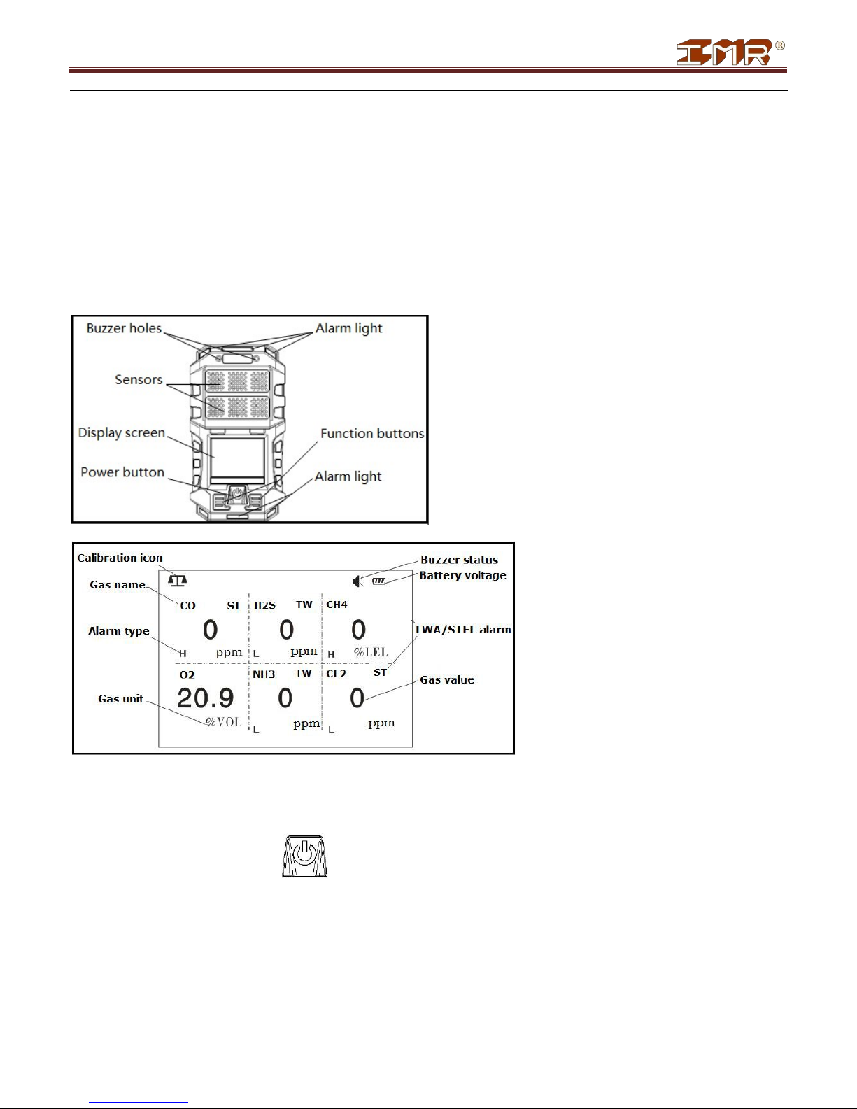
4. Structure and Functions
Appearance Display
information
5. Operation Instructions
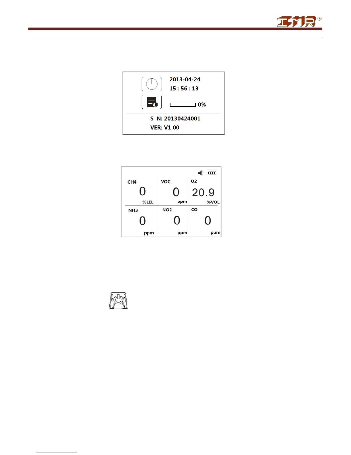
5.1 Power on
When machine is power off, hold for more than 3s and the device will be power on. The screen shows as
below.
IMR Environmental Equipment, Inc.
4
IMR EX660
After power on, the detector will proceed self-test and display is as below drawing.
The device will make self-test on the buzzer, alarm lights and vibrator automatically. After self-test, the device enters
into normal detection status and the screen displays as below.
Note:
If self-test fails, related information will be displayed. For details, please refer to Clause 10 Troubleshooting of
this manual.
If self-test succeeds, the device enters into warm-up period of 3-30s, which depends on the sensor type.
5.2 Power off
In normal detection status, hold for 3 seconds and the screen will show “Shutting down…”. Meanwhile, the
buzzer will give out intermittent beep twice. Then machine is power off.
5.3 Bump test
Every day before using the device, the user is suggested carry out Bump test, so as to check if the device is working
normally.
Test method:
When the device is power on, put it into high level gas environment, which is higher than the preset high alarm point of
the device. If the entire device’s function is ok, then device can be used in the working area.
Note:
If any reading on the screen is beyond the prescribed display error range, please follow Clause 5.7 and 5.8 of this
manual to re-calibrate it.
IMR Environmental Equipment, Inc.
5
IMR EX660
If detector does not response or showing errors, please contact the seller for re pai rin g .
5.4 Menu explanation
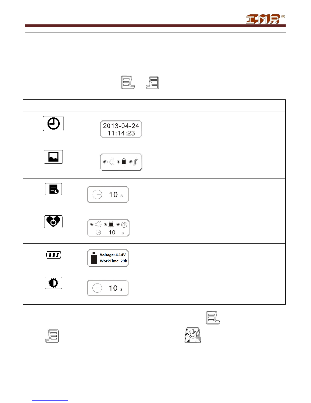
5.4.1 Common menu
In the normal detection interface, press both and simultaneously and the device enters into common
menu setting interface. Below is the button function:
Menu Submenu Remarks
When changing the date or time, the selected bit will
blink.
When changing the mode, the selected bit will blink.
DATE
TIME
ALARM
MODE
RECORD
GAP
CAUTION
MESSAGE
BATTERY MESSAGE
BACKLIGHT
TIME
Set time gap for record saving.
Black box means this item is selected.
Display battery voltage and remaining work time
Backlight time will be increased
by 5s each time.
After enterin g into certain submenu, the user can change the item value by pressing and save the setting by
pressing . The user can also exit without saving changes by pressing .
IMR Environmental Equipment, Inc.
6

IMR EX660
Remarks
CAL.
MANAGE
5.4.2 Advanced menu
In the interface of common menu interface, press both and simultaneously twice. The screen shows
password inputting interface. Input the password by pressing to increase the bit value and press to
confirm the in put password. After inputting the correct password, press to enter into advanced menu interface.
Select the submenu item by pressing and enter into selected submenu by pressing .
Menu Submenu
SAFETY
DEPLOY
ZERO
To set user’s ID.
Zero calibration
DATA
UPLOAD
PERIPHE CONFIG.
Data upload
One mode must be selected
Activate the other function
POWER
One mode must be selected.
LANGUAGE
SELECT
Note: Initial password for entering advanced menu is “0000”.
5.5 Gas detection
The device monitors and displays gas concentration in real time. Once the gas concentration reaches the preset alarm
point, it will initiate alarms.
IMR Environmental Equipment, Inc.
7

IMR EX660
Note:
Do not block sensors in detecting process.
To prolong life span, external filters are suggested in detecting process.
Long time storage, serve physical shock and excessively high concentration may cause zero drift of the gas
sensors. If finding the reading in clean air is not zero, please make zero calibration by following Clause 6.7 and
6.8 of this manual.
5.6 Status review
In normal detection mode, press button in normal operation mode and the screen will show automatically
current temperature, time, STEL value①, TWA value①, the maximum leval of gas②, the minimum level of gas②
since power on.
Note:
① Only for toxic gas.
② Only for o xygen.
5.7 Auto zero calibration
In normal detection mode, hold both and buttons for about 1 second. The device asks for inputting
password. After inputting correct password, the device enters into advanced menu interface.
Move the cursor to icon and press button. The device will make zero calibration automatically. In the
end, a “√” icon displays for gas succeed and “×” for gas failed.
5.8 Calibration
WARNING!
Calibration must be carried out by qualified person. Otherwise,
the device may work wrongly.
5.8.1 Enter the setting interface
While the device is power off, hold both and buttons simultaneously for about 3 seconds. Then, the
device first performs a self test as after power on and after a short delay, the device asks for inputting the password.
After inputting correct password, the device enters into the setting interface shown as below.
IMR Environmental Equipment, Inc.
8

IMR EX660
Press
to move the cursor and the selected icon turns black. Then press
to enter the submenu.
5.8.2 Zero calibration
Select icon and press to enter auto zero calibration interface, shown below. When finished, a “√” icon
displays for gas succeed and “×” for gas failed.
In the auto zero calibration mode, press and the device enters manual zero calibration interface, shown as
below.
When the AD value of the sensor is stable, press to make zero calibration manually. After that, a “√” icon
displays for gas succeed and “×” for gas failed, shown as below.
IMR Environmental Equipment, Inc.
9

IMR EX660
5.8.3 Span Calibration
After zero calibration, the device displays a countdown interface, shown as below.
After that, it displays the calibration gas level, shown as below:
If the level needs to be changed, press to enter the below interface:
Press to move the cursor and press to change the figure. After changing
the figure, press button to save and enter the gas inputting mode, shown as below:
When the device senses the input gas, it displays as below:
IMR Environmental Equipment, Inc.
10

IMR EX660
During this period, if needing to change to manual calibration mode, press . Below is the manual calibration
interface.
Press again to confirm manual calibration. The below 2 drawings show the succeeded and failed manual
calibration.
Once finishing calibration one sensor, the device starts to calibrate the next sensor one by one. The operation is same as
above.
During calibration period, press and the user can skip calibration for some specific sensors.
5.9 Alarm point setting
IMR Environmental Equipment, Inc.
11

IMR EX660
Press
to move the cursor to the
icon and press
button to enter the submenu. Screen shows as
below.
Press to move the cursor to the figure which needs to be adjusted
and press when the figure flashes. Then it enters into the setting interface, shown as below.
Press button to adjust the figure and press to move the cursor. After adjusting, press button to
save. Then the device enters setting interface of the next alarm point.
Note:
H---High alarm point L---Low alarm point
ST---STEL alert point TW---TWA alert point
5.10 Channel setting
Press to move the cursor to icon and press to enter the sumenu. The screen displays as below.
Press to move the cursor to the target channel and this channel box flashes. Press to select or not. If
selected, the center is black; if cancelled, it’s white.
Note:
Select---means this channel is open.
Cancel---means this channel is closed.
Keep pressing until all the channels have been set. The device will save the setting and exit to the normal
detection mode. Closed channels will have a displayed in the channel box. Otherwise, it is open.
IMR Environmental Equipment, Inc.
12

IMR EX660
5.11 Password setting
Move the cursor to the icon and press button to enter the submenu, shown as below.
Press to adjust the figure and press button to move the cursor. After setting, press to save the new
password.
WARNING!
After setting the new password, please remember it clearly.
6. Battery Charging
If low voltage alert is activated or the device cannot be power on, please charge the device immediately in safety area.
Correct the charger connector first to the charge port of the device when power off. Then, connect the plug of the
charger to the suitable power source. The device will be power on automatically and a battery symbol
WARNING!
It’s forbidden to charge the device in working area.
During charging, the detector has no detection function.
Avoid charging when device is power on. Otherwise, the
charging speed will be influenced.
is displayed on the screen. The symbol shows the charging status. When the symbol is all black and no changes, the
charging is finished. When charged enough, the battery symbol is full of black color. Then please disconnect the
charger from both the device and power source.
7. USB Communications (Optional Function)
This function is only available for the device which includes CD and USB data cable.
Connect the USB data cable correctly between the device and computer. Then, run the matching program as instructed
in the manual for the software.
For details, please refer to the software manual.
IMR Environmental Equipment, Inc.
13

IMR EX660
Hand ring
1 pc
Alligator clip
1 pc
Calibration cover
1 pc
Operation manual
1 copy
Charger
1 pc
Normal problem
Possible reasons
Solution
Not power on
Too low voltage
Charge it immediately
System breakdown
Contact the seller
Circuit fault
Contact the seller
Warm-up not finished
Wait till it finishes
Circuit fault
Contact the seller
Sensor overdue
Contact the seller
Sensor drift
Re-calibrate it
Battery voltage has been
Intense electromagnetic
Too much sensor drift
Sensor drift
8. Using and Replacement of Sensor Modules
The device adopts smart sensor modules, which are suggested be calibrated every 6 months If life span is overdue,
please contact the seller for replacement.
9. Standard Accessories
How to use the clips and hand ring?
Belt clip, alligator clip and hand ring could be screwed to the back of the instrument when necessary.
If belt clip is used more frequently, the user can remove the alligator clip first and then install the instrument.
10. Troubleshooting
No response
to gas
Reading of gas level
not accurate
Time and date are
not correct
Zero calibration
function not
available
Display “-0” in
normal detection
status
used up
interference
Charge it and re-set the
time and date
Reset the time and data
Re-calibrate or replace
the sensor module
Make zero calibration
IMR Environmental Equipment, Inc.
14

IMR EX660
11. NOTICE OF USE
Do not drop it from high place and protect it from server shocking.
The instrument may not function properly in an atmosphere with gas of excessively high concentration level.
Please follow this manual to operate the device. Otherwise, it will cause incorrect readings or damage to the
device.
Do not store or operate the device in an environment containing corrosive gas or vapor (for example chlorine of
high concentration). Do not expose the device to other harsh environments (including excessive cold, heat,
humidity, electromagnetic field and intense light).
Clean the housing of the device by using damp cloth. Do not use corrosive agents or hard object which may cause
damage or scuffing on the housing.
Operations of disassembly, replacement and must be carried qualified person.
It’s suggested re-calibrate the device once every 6 months.
Considering environmental protection, do not throw away the old batteries and sensors freely. Please send them to
the specified place.
It’s forbidden to charge the device and upload data to the computer in the hazardous area.
For any application or trouble beyond description in this manual, please the seller for advice.
IMR Environmental Equipment, Inc.
15

IMR EX660
PID
PID Sensor Module for VOC
MOS
MOS Sensor Module for VOC
HCN
0-100 ppm
5 ppm
10 ppm
5 ppm
10 ppm
Gas Detection Range L-Alarm Point H-Alarm Point TWA (ppm) STEL (ppm)
CH4/CO/H2S/O2
LEL
CO/H2S/O2
CH4
C3H8 0-100% LEL 20% LEL 50% LEL N/A N/A
O2 0-30% vol. 19.5% vol. 23.5% vol. N/A N/A
H2S 0-100 ppm 10 ppm 15 ppm 10 ppm 15 ppm
CO 0-1000 ppm 35 ppm 200 ppm 35 ppm 200 ppm
CO 0-2000 ppm 35 ppm 200 ppm 35 ppm 200 ppm
NH3 0-100 ppm 25 ppm 50 ppm 25 ppm 35 ppm
CL2 0-20 ppm 5 ppm 10 ppm 0.5 ppm 1.0 ppm
SO2 0-100 ppm 2 ppm 5 ppm 2 ppm 5 ppm
CO2 0-5000 ppm 1500 ppm 2000 ppm N/A N/A
CH4 0-5% vol. 0.5% vol. 1% vol. N/A N/A
H2 0-100% LEL 20% LEL 50% LEL N/A N/A
H2 0-1000 ppm 35 ppm 250 ppm N/A N/A
NO 0-100 ppm 25 ppm 50 ppm 25 ppm 50 ppm
NO2 0-20 ppm 5 ppm 10 ppm 5 ppm 10 ppm
N/A
0-100% LEL
N/A
0-100% LEL
Annex1—Gas List
N/A
20% LEL
N/A
20% LEL
N/A
50% LEL
N/A
50% LEL
N/A
N/A
N/A
N/A
N/A
N/A
N/A
N/A
PH3 0-20 ppm 5 ppm 10 ppm 5 ppm 10 ppm
HCI 0-20 ppm 5 ppm 10 ppm 5 ppm 10 ppm
IMR Environmental Equipment, Inc.
16

IMR EX660
IMR Environmental Equipment, Inc.
3634 Central Ave.
St. Petersburg, FL 33711
Phone: 727-328-2818
E-mail: info@imrusa.com
The manufacturer observ es t he ri g ht of amending the
operation manual without informing the users in advance.
IMR Environmental Equipment, Inc.
WARNING!
17
 Loading...