

IMR 2800 P
IMR 2800 A
IMR 2800 IR
ENVIRONMENTAL EQUIPMENT, INC.
3632 Central Ave.
St. Petersburg, FL 33711
USA
Phone: 727-328-2818
E-Mail: info@imrusa.com
Web: WWW.IMRUSA.COM

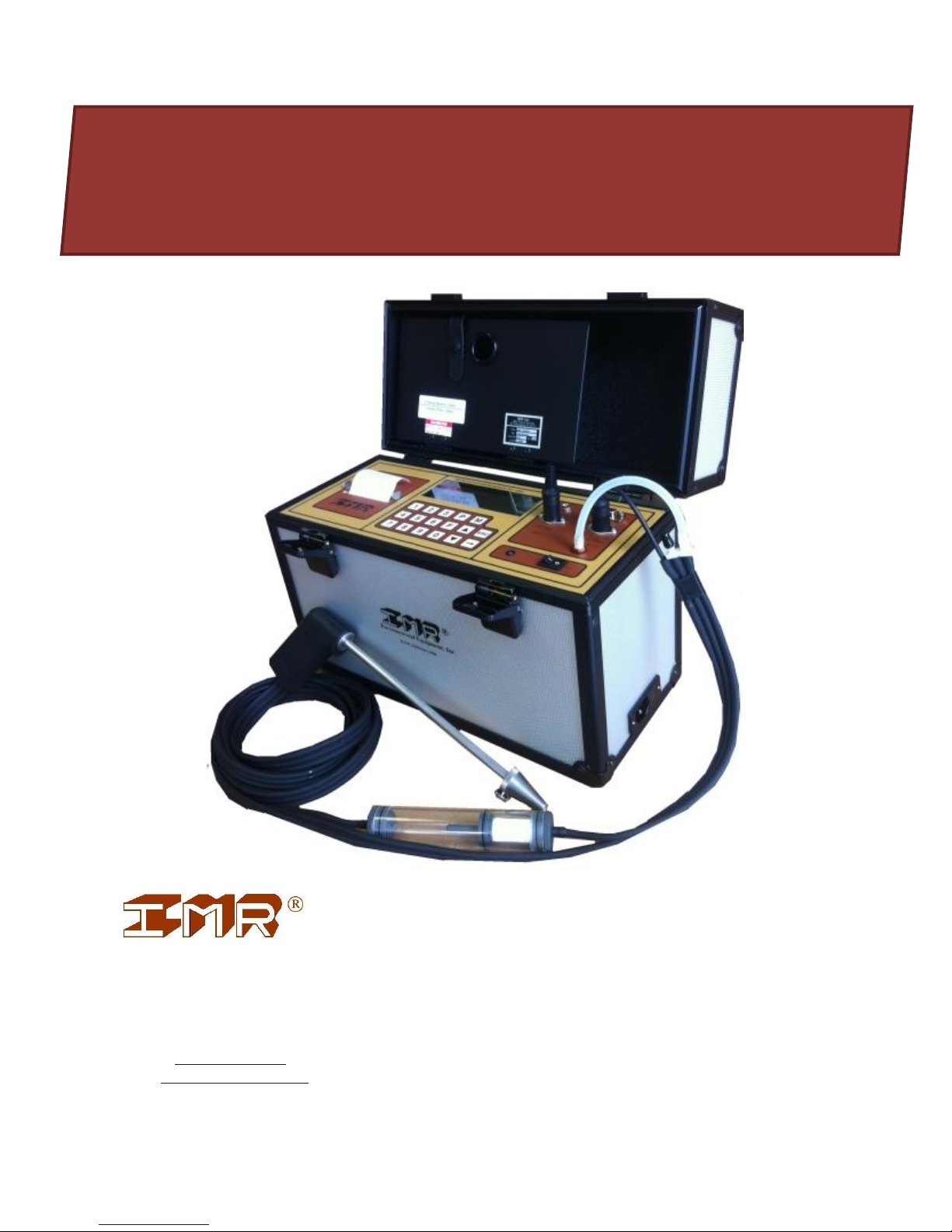
IMR® 2800
TABLE OF CONTENTS
INTRODUCTION __________________________________________________________ 4
SAFETY INSTRUCTIONS ___________________________________________________ 4
1 DESCRIPTION __________________________________________________________ 5
1.1 FUNDAMENTALS __________________________________________________________ 6
2 SYSTEM DESCRIPTION ______________________________________________________ 7
2.1 OVERVIEW ________________________________________________________________ 7
2.2 FUNCTION OVERVIEW _____________________________________________________ 8
2.3 TECHNICAL DATA - STANDARD RANGES ___________________________________ 9
TG Flue gas temperature _________________________________________________________ 9
2.4 SYSTEM CONNECTIONS __________________________________________________ 11
2.4.1 Probe ________________________________________________________________________ 11
2.4.2 Ambient air temperature plug ____________________________________________________ 13
2.4.3 Gas fitting _____________________________________________________________________ 13
2.4.4 Draft fitting ___________________________________________________________________ 13
2.4.5 LED _________________________________________________________________________ 13
2.4.6 Differential pressure fitting (if equipped) ___________________________________________ 13
2.4.7 RS232 interface ________________________________________________________________ 14
2.5 POWER __________________________________________________________________ 15
2.6 BUTTON FUNCTIONS _________________________________________________ 16
3 OPERATION ___________________________________________________________ 17
3.1 OVERVIEW _______________________________________________________________ 17
3.2 TURNING ON _____________________________________________________________ 18
3.3 FUEL TYPE SELECTION ___________________________________________________ 19
3.4 MEASUREMENT MENU ___________________________________________________ 20
3.4.1 Main menu ____________________________________________________________________ 21
3.4.2 Store a measurement ____________________________________________________________ 22
3.4.3 Printout ______________________________________________________________________ 23
3.4.4 Feed _________________________________________________________________________ 23
3.5 SUBMENUS OF THE MAIN MENU __________________________________________ 24
3.5.1 Choice ppm/mg ________________________________________________________________ 25
3.5.2 Config. printer _________________________________________________________________ 26
3.5.3 Statistics ______________________________________________________________________ 27
3.5.4 Memory ______________________________________________________________________ 29
3.5.5 Pressure ______________________________________________________________________ 30
3.5.6 Standby ______________________________________________________________________ 31
3.5.7 Select fuel _____________________________________________________________________ 31
3.5.8 Organization __________________________________________________________________ 32
3.5.8.1 Device status _____________________________________________________________ 32
3.5.8.2 Set date / time ____________________________________________________________ 33
3.5.8.3 Interface ________________________________________________________________ 34
3.5.8.4 Configuration ____________________________________________________________ 37
3.5.8.5 Change fuel parameters _____________________________________________________ 38
3.5.8.6 Station __________________________________________________________________ 38
3.5.8.7 Select language (if equipped) ________________________________ ________________ 38
2 IMR Environmental Equipment, Inc.

IMR® 2800
3.5.8.8 Switch Gas 1 / Gas 2 (if equipped) ____________________________________________ 39
3.5.9 Soot detection (if equipped) ________________________________ ______________________ 39
3.5.10 Recalibration _________________________________________________________________ 39
4 CALCULATIONS ________________________________________________________ 40
4.1 EXCESS AIR ______________________________________________________________ 40
4.2 CARBON DIOXIDE CO2 ____________________________________________________ 40
4.3 HEAT LOSSES ____________________________________________________________ 41
4.4 CONVERTING PPM INTO VOLUME/WEIGHT RATIO ________________________ 44
4.5 CONVERTING PPM INTO VOLUME/WEIGHT RATIO WITH REF. O2 __________ 44
4.6 NOx (NO+NO2) ____________________________________________________________ 44
5 UNIT MAINTENANCE ___________________________________________________ 45
6 ERROR MESSAGES _____________________________________________________ 46
7 WARRANTY ____________________________________________________________ 48
8 SPARE PARTS __________________________________________________________ 49
9 IMR ___________________________________________________________________ 50
3 IMR Environmental Equipment, Inc.

IMR® 2800
IMR reserves the right to adopt technical modifications without prior notice.
INTRODUCTION
Thank you for purchasing the IMR® 2800 combustion gas analyzer.
Please read the following instructions before operating the unit for the first time.
Proper handling is necessary to make full use of the outstanding performance and features of
this combustion gas analyzer.
IMPORTANT INFORMATION:
Use the instrument just within the recommended temperature range.
Never measure without the dust filter and condensation trap.
The dust filter must be cleaned/replaced when dirty.
The c8ondensation trap must be checked and the condensed water removed if necessary.
IMR or an authorized service facility must re-calibrate the IMR 2800 once a year to
ensure accuracy and performance.
SAFETY INSTRUCTIONS
Please make sure that you read this section carefully for use of your new combustion gas
analyzer.
Follow all warnings and instructions marked on the product or displayed on the screen.
The AC inlet should only be connected to a socket with a protective earth contact.
Any adjustment or maintenance of the analyzer under voltage should be avoided.
The maintenance of the analyzer should be done by qualified personal and the instrument
must be turned off and unplugged.
Do not take the analyzer out of the box during the warranty period. If you do so, then the
warranty is null and void.
Do not use this analyzer in water.
Never spill water or any liquid on the analyzer.
4 IMR Environmental Equipment, Inc.

IMR® 2800
O2
CO
NO
NO2
SO2
Additional
Sensor(s)
Printer
Memory
RS232
Interface
Ambient
Temp.
Soot
Draft
IMR 2800
X X X X X O X X X X O
X
1 DESCRIPTION
The IMR 2800 is a state of the art combustion gas analyzer.
Table 1: IMR 2800
X - standard O - optional
Maximum 8 electrochemical sensors
The IMR 2800 calculates the parameters below:
- Excess air / Lambda
- Heat losses / Efficiency
- Carbon dioxide CO2
Optional features: - Differential draft measurement
- Gas Flow measurement (m/s) with Pitot tube
- HCl, N2O, CL2, H2, NH3, HC, H2S measurement
- CO2, CH4/HC and N2O NDIR sensors available
- Speed RPM
- Soot Measurement
- High temperature gas sampling probes (ceramic, PT-RhPT)
(up to 1500C / 2732F)
- Gas-sampling probes with different lengths
- NOx (NO + NO2)
- Additional Instruments: RPM Meter, Soot Meter
5 IMR Environmental Equipment, Inc.

IMR® 2800
1.1 FUNDAMENTALS
Gas flow
A built-in sampling pump is drawing the flue gas through the gas-sampling probe into the
analyzer.
1. The gas flows through the gas-sampling probe to the condensation trap.
2. Then the gas passes through a particle filter where dust particles are removed.
3. Then the gas enters the sensor chamber.
Gas temperature
The gas temperature is measured by a thermocouple located at the tip of the gas-sampling
probe.
Electrochemical sensors
Each electrochemical sensor measures the concentration of a specific gas.
Electrochemical sensors can be damaged
- if exposed to small particles - never measure without a dust filter
- if water / condensation comes in contact with the sensors - empty condensation
trap
Service / Calibration
A “Service” message will be displayed after 1000 hours or after one year of operating time.
IMR Environmental Equipment, Inc. recommends checking the calibration once a year.
Operating Temperature
50oF..104oF / 10oC..40oC
If the unit is brought in from the cold, then it should be allowed to warm up for a few minutes.
Storage Procedures: IMPORTANT!
Storage Temperature
-4oF..122oF / -2oC..50oC
When not in use or in storage, please make sure to keep the analyzer plugged into a wall outlet
(AC).
This ensures that the analyzer maintains a constant battery charge and function properly if
needed.
Prolonged periods of disuse without charging the battery may result in a weak battery and the
battery can lose its ability to hold the charge.
6 IMR Environmental Equipment, Inc.

IMR® 2800
2 SYSTEM DESCRIPTION
2.1 OVERVIEW
Please check now if the unit is equipped with all the ordered features and accessories.
Features and Accessories (if equipped):
- Backlit LCD
- Keypad
- Gas sampling probe
- Ambient temperature probe
- Thermal printer
- RS232 interface
- Rechargeable battery
- Draft measurement
- Soot measurement w/ soot filter paper and comparison scale
- Memory
- O2 electrochemical sensor
- CO electrochemical sensor
- NO electrochemical sensor
- NO2 electrochemical sensor
- SO2 electrochemical sensor
- Additional sensor(s)
- Case
- Manual
- Power Cord
- Calibration certificate
7 IMR Environmental Equipment, Inc.
IMR® 2800
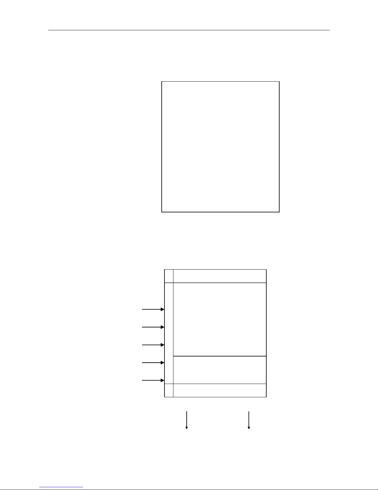
Measurements
Gas Temperature
Ambient Temperature
Draft
Soot
O2
CO, NO, SO2, NO2, HC
(max. 7 more sensors)
Calculations
CO2
Losses
Excess Air
NOx (NO+NO2)
I
n
p
u
t
s
FUNCTIONS
IMR 2800
Gas Temperature
Ambient Temperature
Gas sensors
Draft
Soot
Printer
RS232
Calculations
OUTPUTS
2.2 FUNCTION OVERVIEW
8 IMR Environmental Equipment, Inc.

IMR® 2800
PARAMETER
PRINCIPLE
RESOLUTION
ACCURACY
RANGE**
STANDARD
O2 Oxygen
Electro-chemical
cell
0.1 Vol.%
0.2 Vol. %
0-20.9 Vol. %
CO Carbon
monoxide
Electro-chemical
cell
NDIR
1 ppm
0.001 Vol.%
Z
02000/4000ppm
0-10/20 Vol.%
NDIR
Optional
NO Nitric oxide
Electro-chemical
cell
1 ppm
Z
0-2000 ppm
NO2 Nitrogen
dioxide
Electro-chemical
cell
0.1 ppm
Z
0- 100 ppm
SO2 Sulfur
dioxide
Electro-chemical
cell
1 ppm
Z
0-4000 ppm
H2S Hydrogen
Sulfide
Electro-chemical
cell
0.1 ppm
Z
0- 200 ppm
HC/CH4
Hydrocarbons
Pellistor or NDIR
0.1 %
Z
0-100% LEL
TG Flue gas
temperature
NiCr-Ni
thermocouple
1°C/1°F
2 %
-4F - 2192F
0C - 1200C
TA Air
temperature
Semiconductor
1°C/1°F
2 %
-4F / 248F
0C - 120C
P Draft
Solid state
0.01 hPa
2 %
40 hPa
NOx Nitrogen
oxides
Calculation
1 ppm
Z
0-NOx max
CO2 Carbon
dioxide
Calculation
0.1 Vol.%
0.2 Vol. %
0- CO2 max
CO2 Carbon
dioxide
NDIR
0.01 Vol.%
0.2 Vol. %
0-20 Vol. %
NH3 Ammonia
Electro-chemical
1 ppm
Z
0-1000/5000
ppm
N2O Nitrous Oxide
NDIR
0.001 Vol. %
Z
0-1 Vol. %
HCl Hydrogen
Chloride
Electro-chemical
1 ppm
Z
0-200 ppm
Cl2 Chlorine
Electro-chemical
1 ppm
Z
0-5000 ppm
H2 Hydrogen
Electro-chemical
1 ppm
Z
0-10000 ppm
Losses / Efficiency
Calculation
0.1 %
0.1 %
0-99.9 %
Excess Air /
Lambda
Calculation
0.1 %
0.1 %
1.0-9.99
Soot
Filter paper
method
0-9
Velocity with Pitot
tube
Solid state
0.01 m/s
2 %
0-80 m/s
RPM Meter
Solid state
100 RPM
2 %
180-10000
RPM
2.3 TECHNICAL DATA - STANDARD RANGES
Other measurement ranges and probe lengths are optional available.
Table 2: Technical Data
** Different/customized ranges available. Equipped with a maximum of 8 gas sensors
Z = 0 - 20 % of whole measurement range ± 5 % of maximum measurement
21 - 100 % of whole measurement range ± 1 % of displayed measurement
9 IMR Environmental Equipment, Inc.

IMR® 2800
Power Inlet 110VAC/60Hz or 230VAC/50Hz
Battery Sealed lead acid 12VDC- Five-hour charge time
Display 4-line, 20-character illuminated LCD
Printer Thermal printer - paper width 58mm - built-in
Gas sampling probe If the unit is equipped with soot measurement
- Type S, probe length 10.6" / 270mm, hose 11.5' / 3.5m
If the unit is not equipped with soot measurement
- Type E, probe length 9.8" / 250mm, hose 8.2' / 2.5m
Ambient air probe Ambient air temperature plug
Condensation Trap Inline with integrated filter
Filter In-line - four micron - washable
Case Rugged wood/aluminum case with compartment for gas sampling
probe, power cord and accessories.
Operating temperature 50oF..104oF / 10oC..40oC
Storing temperature -4oF..122oF / -20oC..50oC
Calibration Automatic 3-minute zero calibration
Fuels USA
Natural gas, Propane, Kerosene, Distillate #1, Anthracite coal,
Bituminous coal, Fuel #2, Fuel #5, Fuel #6, Bagasse, Wood, Bark,
Special fuel A, Special fuel B, Special fuel C, Special fuel D
European
Fuel oil extra light, Natural gas, Town gas, Coalgas, Liquid gas,
Hard coal hb 1950, Wood (air dry), Fuel oil light, Fuel oil heavy,
Coaltar oil, Liquid gas air ventil., Liquid gas air, Propane ventil.,
Propane, Butane ventil., Butane, Propane / Butane ventil.,
Propane / Butane, Biogas ventil., Biogas, Hard coal hb 7450,
Hard coal hb 7170, Hard coal hb 2230, Special fuel A, Special fuel
B, Special fuel C, Special fuel D
10 IMR Environmental Equipment, Inc.

IMR® 2800
2.4 SYSTEM CONNECTIONS
2.4.1 Probe
The gas-sampling probe plug and hose has to be connected to the analyzer before it can be
turned on and must stay connected during the whole measurement.
If the gas-sampling probe is not connected, then the analyzer cannot perform an accurate
calibration and an error message will be displayed.
Type S (if equipped with soot measurement)
The probe S has two hoses. One for the flue gas measurement and one for the draft
measurement. Both hoses must be connected to their fittings at all time.
It also has a connection line to connect the thermocouple with the analyzer.
a) Thermocouple - Connect the thermocouple plug (5-pos) with the
'flue gas temp' socket of the analyzer
b) Flue gas - Connect the hose, which has the condensation trap
inline to the barbed fitting 'gas input'
c) Draft - Connect the second hose to the barbed fitting
'draft'
Type E
The probe E has one hose for the flue gas measurement and the draft measurement.
It also has a connection line to connect the thermocouple with the analyzer.
a) Thermocouple - Connect the thermocouple plug (5-pos) with the
'flue gas temp' socket of the analyzer
b) Flue gas - Connect the hose to the barbed fitting 'gas input'
The hose must be connected to the 'gas input' fitting for the flue gas measurement.
The hose must be connected to the 'draft' fitting only for the draft measurement and it must be
connected back to the 'gas input' fitting after the draft measurement is completed.
Type C (if equipped)
The probe C is a ceramic probe with a Pt-RhPt thermocouple and it is used for high
temperatures. The temperature range is 302F-2732F / 150C-1500C.
It has the same connections as the probe E.
11 IMR Environmental Equipment, Inc.

IMR® 2800
Gas sampling probe (type S) connection:
12 IMR Environmental Equipment, Inc.

IMR® 2800
2.4.2 Ambient air temperature plug
The ambient air temperature plug must be connected to the instrument at all time.
If the ambient air temperature plug is not connected, then the unit shows an error message.
The ambient air temperature plug measures the temperature of the air that is used for the
combustion process.
The measured temperature is needed for various calculations.
Connect the plug (4-pos) with the 'air temp' socket of the analyzer.
2.4.3 Gas fitting
The gas hose of the gas-sampling probe must be connected to the gas fitting.
2.4.4 Draft fitting
The draft hose of the gas-sampling probe must be connected to the draft fitting.
2.4.5 LED
The LED shows the power status of the unit.
RED: battery powered
GREEN: AC connected and turned off (charging the battery)
YELLOW: AC connected and turned on
2.4.6 Differential pressure fitting (if equipped)
The analyzer is equipped with a third barbed fitting for a differential pressure measurement.
The differential pressure is the pressure that is measured between the 'draft' fitting and this 3rd
fitting.
Connect a hose to this fitting and insert it into the medium and start the regular draft
measurement. The draft measurement measures now the differential pressure from the
medium to the flue gas, where the gas-sampling probe is inserted.
13 IMR Environmental Equipment, Inc.
IMR® 2800
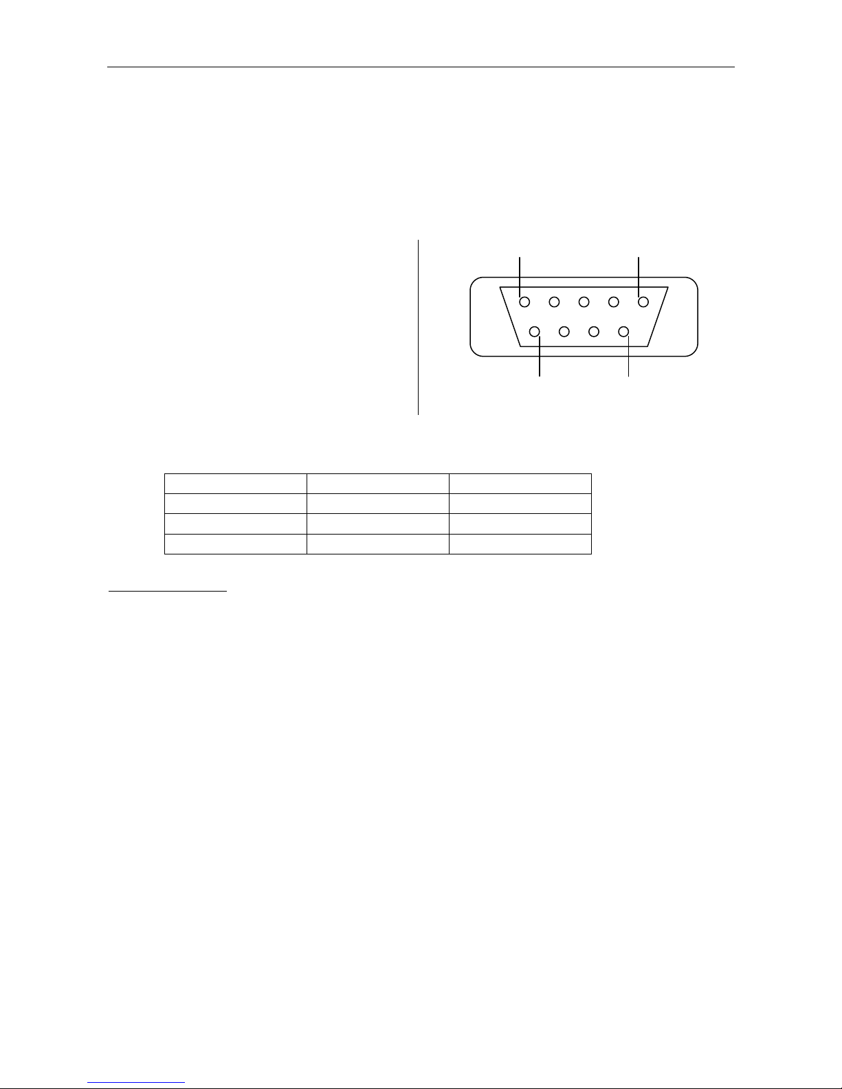
1-
23- TXD transmit data
4-
5- GND ground
678- CTS clear to send
9-
5 1
9 6
IMR 2800
PC 9-pos
PC 25-pos
3 TXD
2 RXD
3 RXD
5 GND
5 GND
7 GND
8 CTS
7 RTS
4 RTS
2.4.7 RS232 interface
The RS232 serial interface can be used to transfer data from the analyzer to a PC.
Real time data or stored data can be transferred (ASCII signs are getting transferred).
The serial connection to a PC must be a 'Null-modem connection'.
The IMR 2800 has a 9-pos. female D-Sub connector on the front panel.
RS232 female connector 9-pos.
Connection to a PC (null-modem connection):
Serial data format
A character has 8 data bits; no parity and 2 stop bits.
ASCII "Computer" format:
Start ()
Station
Fuel
Units (ppm, etc.)
NOx (according TA-Luft)(1)
Date
Time
No. of samples
Time of samples
Room Temperature
O2
CO
HC
SO2
NO2
NO
Draft
Gas Temperature
CO2
Losses
Excess Air
Stop ()
14 IMR Environmental Equipment, Inc.

IMR® 2800
2.5 POWER
The IMR 2800 works on 230VAC/50Hz or 110VAC/60Hz. A fuse selector next to the AC
inlet sets the voltage.
The analyzer is able to work without being connected to the AC by using the power of the
internal rechargeable battery lead acid battery.
However IMR recommends connecting the analyzer always to the AC during a measurement
or during storage.
15 IMR Environmental Equipment, Inc.

IMR® 2800
2.6 BUTTON FUNCTIONS
"0" - "9" - Numeric buttons for numbers
"P" - Prints a measurement
"measurement menu" - complete measurement
submenu "pressure" - draft measurement
"M" - Stores a measurement
"F" - Feed
"^" - Scroll up
"v" - Scroll down
"ESC" - Back to the measurement menu
"" - Enter / confirm
16 IMR Environmental Equipment, Inc.

IMR® 2800
Connect gas sampling probe and
ambient air plug
(Do not put the gas sampling
probe into the flue gas at this
time)
"On/Off" - Turn the unit on
3 min Calibration and self check
Press any key after calibration is
Finished
Fuel type selection
"^", "v" - Select fuel type
"" - Confirm selected fuel type
Measurement menu
"P" - print measurement
"^", "v" - scroll first line
"M" - store measurement
""
Main menu
-Choice ppm / mg
-Config. Printer
-Statistics
-Memory
-Pressure
-Standby
-Select fuel
-Organization
-Soot detection
-Recalibration
"^", "v" - Select submenu
"" - Confirm and enter submenu
"ESC" - Back to measurement menu
3 OPERATION
3.1 OVERVIEW
17 IMR Environmental Equipment, Inc.

IMR® 2800
IMR 2800P
FLUE GAS
ANALYZING COMPUTER
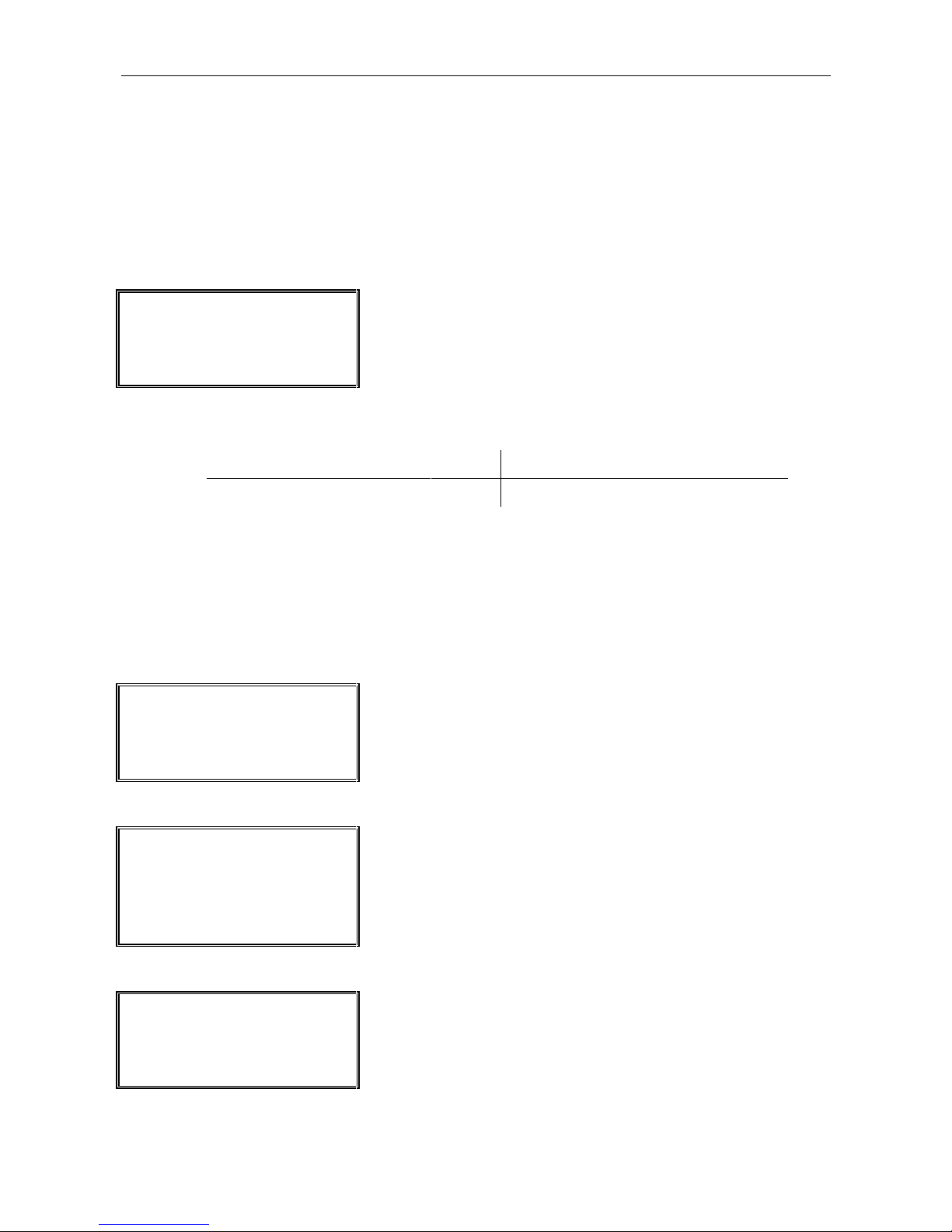
Turn the "On/Off"- button to "On" and the unit starts with the
zero calibration.
IMR 2800P
Calibration 2:00 PM
174 seconds
The zero calibration takes 180 seconds and the unit is checking
all sensors and sets all the values to its zero point.
IMR 2800P
Calibration done.
Press any key
Press any key after the calibration is finished.
3.2 TURNING ON
Make sure to connect the gas sampling probe and the ambient air temperature plug to the
analyzer and do not insert the gas-sampling probe into the flue gas.
18 IMR Environmental Equipment, Inc.

IMR® 2800
===Select fuel===
fuel oil. ex. lgh.
natural gas
town gas
Select the fuel with the "^" or "v" button.
Confirm the selection by pressing the "" button.
The analyzer enters the measurement menu after the
confirmation.
Move arrow selector up
^
Back to measurement menu
ESC
Move arrow selector down
v
Confirm selection
USA: - Natural gas
- Propane
- Kerosene
- Distillate #1
- Anthracite coal
- Bituminous coal
- Fuel #2
- Fuel #5
- Fuel #6
- Bagasse
- Wood
- Bark
European: - Fuel oil extra light
- Natural gas
- Town gas
- Coalgas
- Liquid gas
- Hard coal hb 1950
- Wood (air dry)
- Fuel oil light
- Fuel oil heavy
- Coaltar oil
- Liquid gas air ventil.
- Liquid gas air
- Propane ventil.
- Propane
- Butane ventil.
- Butane
- Propane / Butane ventil.
- Propane / Butane
- Biogas ventil.
- Biogas
- Hard coal hb 7450
- Hard coal hb 7170
- Hard coal hb 2230
3.3 FUEL TYPE SELECTION
The IMR 2800 has most common fuels programmed and 4 more fuel types are programmable
by the user.
After the calibration is finished the analyzer needs to know, which fuel is used by the
combustion process. This information is necessary to calculate the combustion parameters.
Active buttons
Fuel types:
Programmable fuel:
If the used fuel type is not programmed, then a special fuel type can be entered with its
parameters.
19 IMR Environmental Equipment, Inc.

IMR® 2800
CO2 0.0%
T-gas 75.2oF O2 20.9%
CO ppm NO ppm SO2ppm
0 0 0
The first line shows these different values:
CO2, T-room, losses, excess air, fuel type
Scroll first line
^ , v
Print measurement
P
Store measurement
M
Line feed
F
Enter main menu
Editing the fuel parameters for the special fuel type has to be done in the submenu
"organization".
3.4 MEASUREMENT MENU
Measurement
- Put the gas sampling probe into the flue gas and check for the highest temperature. Lock the
probe tube with the cone at this point.
- The sensors need approximately 3 minutes for an accurate and stable reading.
The measurement menu shows all measured and calculated parameters as well as the fuel
type.
The first line scrolls automatically every 10 seconds. However one value can be selected by
using the "^" and /or "v" button.
Active buttons
20 IMR Environmental Equipment, Inc.

IMR® 2800
Choice ppm/mg
Config. Printer
Statistics
Memory 50
The arrow selector has to be in front of the submenu by using
the "^" and "v" button.
Enter the submenu by pressing the "" button.
4 submenus are shown on the LCD. To see other submenus
scroll with the "^" and "v" button.
Move arrow selector up
^
Back to measurement menu
ESC
Move arrow selector down
v
Line feed
F
Enter submenu
Choice ppm / mg
ppm - mg/m3 - mg (Ref.O2)
Config. Printer
Set printout intervals
Statistics
Start statistics for calculation of mean value and standard deviation
Memory
Print memory
Pressure
Start draft measurement
Standby
Standby mode
Select fuel
Select fuel type
Organization
Date/time, configuration of the analyzer, interface
Soot detection
Start soot measurement
New calibration
Start new calibration
3.4.1 Main menu
Press the "" button in the measurement menu to enter the main menu.
The main menu sets date, time, units, fuel type and much more.
Active buttons
Main Menu
21 IMR Environmental Equipment, Inc.

IMR® 2800
Choice ppm/mg
Config. Printer
Statistics
Memory 46
Memory status = 46
The analyzer can store 46 more measurements.
4 measurements are already stored
3.4.2 Store a measurement
Press the "M" button to store the current measurement.
Each stored measurement consists of date, time, fuel type and all measured and calculated
parameters.
The IMR 2800 can store up to 50 measurements.
Memory status
The memory status is located in the main menu behind the submenu "memory".
See the description of the submenu "memory" on how to select and print the stored data.
22 IMR Environmental Equipment, Inc.

IMR® 2800
*******************
* IMR 2800P *
*******************
09/16/1999 01:31PM
fuel oil ex. lgh.
T-room 75oF
T-gas 75oF
CO2 0.0%
O2 20.9%
CO 0ppm
SO2 0ppm
NO 0ppm
qA +++++
LAMBDA +++++
3.4.3 Printout
The IMR 2800 is equipped with a built-in thermal printer. The paper width is 58mm.
Important: - Use only original IMR thermal paper.
- Make sure that the thermal side of the paper is on the correct side.
The printer prints only on the thermal side.
Press the "P" button to print the current measurement.
Change paper
Unscrew the two thumbscrews and remove the printer cover from the front panel.
Take the old paper roll out and put the new roll in. Make sure the thermal side is on the
correct side. Close the cover and fasten the two thumbscrews.
3.4.4 Feed
Press "F" to do a line feed.
23 IMR Environmental Equipment, Inc.

IMR® 2800
Choice ppm / mg
ppm - mg/m3 - mg (Ref.O2)
Config. Printer
Set printout intervals
Statistics
Start statistics for calculation of mean value and standard deviation
Memory
Print memory
Pressure
Start draft measurement
Standby
Standby mode
Select fuel
Select fuel type
Organization
Date/time, configuration of the analyzer, interface
Soot detection
Start soot measurement
New calibration
Start new calibration
Move arrow selector up
^
Back to measurement menu
ESC
Move arrow selector down
v
Line feed
F
Enter submenu
Choice ppm/mg
Config. Printer
Statistics
Memory 50
"" - indicator :
Indicates an active submenu (e.g. statistics is running)
3.5 SUBMENUS OF THE MAIN MENU
Active buttons
A submenu can only be entered from the main menu.
Select the submenu and then press "" button to enter the submenu.
24 IMR Environmental Equipment, Inc.

IMR® 2800
=== Choice ppm/mg ===
Display ppm
Display mg
mg ref. O2
Move the arrow selector up or down ("^","v") to select a unit.
Confirm the selected unit by pressing the "" button.
3 units are shown on the LCD. To see the other possible units
scroll with the "^" and "v" button.
Move arrow selector up
^
Back to measurement menu
ESC
Move arrow selector down
v
Confirm unit selection
Stop stat.
Press any key
If statistics is activated, then the units cannot be changed.
3.5.1 Choice ppm/mg
The units of CO, NO, NO2, SO2 are selectable: - ppm
- mg/m3
- mg/m3 (ref.O2)
- mg/m3 (NONO2)
- mg/m3 (ref.O2 / NONO2)
CO, NO, NO2 and SO2 are measured in ppm and the default setting is ppm.
Please see chapter 4 on how to calculate the different units.
Active buttons
ppm:
The measured values of the toxic sensors are shown in ppm.
mg:
The measured values of the toxic sensors are shown in mg/m3.
mg ref. O2:
The measured values of the toxic sensors are shown in mg/m3 (reference to O2)
The symbol on the LCD is "mg^".
mg NO NO2
The measured values of the toxic sensors are shown in mg/m3 with NO calculated to NO2.
mg ref. O2 NO NO2
The measured values of the toxic sensors are shown in mg/m3 (reference O2) with NO
calculated to NO2
Important:
25 IMR Environmental Equipment, Inc.

IMR® 2800
== Config. Printer ==
Printer off
Print protocol
Print memory
Move the arrow selector up or down ("^","v") to select a
submenu.
Confirm the submenu by pressing the "" button.
Move arrow selector up
^
Back to measurement menu
ESC
Move arrow selector down
v
Confirm selection
===Confi. printer===
--- print protocol -- Minutes/Output
15
The time between the printouts can be selected from 10 to 99
minutes by using the numeric keys.
Confirm the setting by pressing the"" button
Continuous output
Press any key
If statistics and RS 232 transfer are activated, then the print
intervals cannot be started.
Memory empty
Press any key
If there are no measurements stored, the display shows.
3.5.2 Config. printer
This menu sets print intervals and prints the memory.
Active buttons
Printer off:
Stops the interval printouts.
Print protocol:
Sets print intervals: one printout every x minutes
The print intervals can be set for a measurement printout or a statistics printout.
The first printout is after one minute and the following printouts are every x minutes.
Print memory:
This submenu prints the last stored measurement.
26 IMR Environmental Equipment, Inc.

IMR® 2800
===Statistics===
Stop stat.
Start stat.
Print stat.
Move the arrow selector up or down ("^","v") to select a
submenu.
Confirm the submenu by pressing the "" button.
Move arrow selector up
^
Back to measurement menu
ESC
Move arrow selector down
v
Confirm selection
Mean value
m = (x) / n
Standard deviation
x = measured value
n = number of samples
s = (1/(n-1) * (x-m))
3.5.3 Statistics
The statistics menu starts, stops and prints the statistical measurement.
Active buttons
Statistics calculates mean values and standard deviations of the measured and calculated
parameters.
Calculation:
Stop statistics:
Stops the statistics calculation.
Start statistics:
Starts calculation of mean value and standard deviation. A calculation is made every second.
If the statistics is running, then these submenus cannot be entered:
- Choice ppm/mg
- Select fuel
- Organization / Change fuel parameters
- Organization / Set date/time
27 IMR Environmental Equipment, Inc.

IMR® 2800
Start stat.
Press any key
If the statistic calculation is not running, then this message is
displayed.
********************
* IMR 2800P *
********************
09/16/1999 02:32pm
fuel oil ex. lgh.
# of samples 60
Mean value Std. dev
T-room 75oF 0
T-gas 75oF 0
CO2 0.0% 0.0
O2 20.9% 0.0
CO 0ppm 0
SO2 0ppm 0
NO 0ppm 0
qA +++++% 0.0
LAMBDA ++++ 0.00
Print statistics:
Prints the statistics.
28 IMR Environmental Equipment, Inc.
IMR® 2800
===Memory===
Clear memory
Print memory
Move the arrow selector up or down ("^","v") to select a
submenu.
Confirm the submenu by pressing the "" button.
Move arrow selector up
^
Back to measurement menu
ESC
Move arrow selector down
v
Confirm selection
===Memory===
---Print memory-- sample all
Select all measurements or only one measurement by using the
"^" and /or "v" button to select the measurement.
To print the selected number press the "" button.
=== Memory ===
---Print memory ---
Station 0
sample 1
Example: First stored measurement (from station 0) is selected.
Memory empty
Press any key
If the memory is empty, then this message appears.
3.5.4 Memory
This menu deletes and prints the stored measurements.
If the analyzer is turned off, then all the stored values are deleted. Keep the unit in standby
mode if the stored measurements are important and need to be printed later on.
Active buttons
Clear memory:
Deletes all the stored measurements.
Print memory:
Prints one stored measurement or all stored measurements.
29 IMR Environmental Equipment, Inc.

IMR® 2800
===Pressure===
exchange pipe
Pressure 0.00 hPa
The draft measurement starts as soon as the hose is connected to
the draft fitting.
Back to measurement menu
ESC
Back to measurement menu
Prints draft measurement
P
===Pressure==
Pressure -0.37 hPa
Confirm
The draft measurement is on the LCD.
Press the "P" button to print the draft measurement.
Press the "" button to return to the measurement menu.
16.09.1999 03:41:12pm
Pressure -0.042 hPa
-------------------------------------
Draft printout
3.5.5 Pressure
Starts the draft measurement.
The pump is turned off.
Important (gas-sampling probe E)
The draft hose of the gas-sampling probe has to be connected to the draft fitting.
Active buttons
Important (gas-sampling probe E):
Remove the hose after the measurement from the draft fitting and put it back on the gas inlet
fitting.
30 IMR Environmental Equipment, Inc.

IMR® 2800
Standby
Press any key
The LCD shows at the beginning of the mode this message.
Later on it will turn off the LCD.
Press any key to start the unit and stop the standby mode.
Stop stat.
Press any key
If the statistics is running, then the fuel type cannot be changed.
3.5.6 Standby
Standby mode conserves power by switching off the pump and the LCD.
All activated modes will be stopped. The standby mode is used to save the stored
measurements.
3.5.7 Select fuel
Please see section 3.3 on how to select a fuel type.
31 IMR Environmental Equipment, Inc.

IMR® 2800
Device status
Checks operating hours and overflows
Set date/time
Sets date and time
Interface
Sets Baud Rate, continuous output, format
Configuration
Program version, sensor ranges
Change fuel par.
Changing fuel type constants
Station
Edit station numbers
Select language
English - German – French
Switch Gas 1 / Gas 2
Switches between Gas 1 and Gas 1 sensors
===Organization===
Device status
Set date/time
Interface
Move the arrow selector up or down ("^","v") to select a
submenu.
Enter the submenu by pressing the "" button.
3 submenus are shown on the LCD. To see the other submenus
scroll with the "^" and "v" button.
Move arrow selector up
^
Back to measurement menu
ESC
Move arrow selector down
v
Confirm selection
===Organization===
---Device status--Lifetime (hours)
30.61
The operating hours are displayed in hours and hundredths of an
hour.
Scroll to the overflow display of the various sensors by using
the "^" and / or "v" button.
Press "ESC" to return to the measurement menu
3.5.8 Organization
The submenu organization has different menus to set date, time, interface RS232 and check
device status and much more.
Submenus
Active buttons
3.5.8.1 Device status
The device status menu shows information about the operating hours of the unit as well as the
overflows of the sensors.
Overflow: A measurement above the measuring range of a sensor is called 'overflow'.
An overflow damages the sensor and it can decrease the lifetime of the sensor.
32 IMR Environmental Equipment, Inc.

IMR® 2800
===Organization===
---Device status---
Overflows
CO 2
Example: CO sensor was twice above its measuring range
Scroll to the other sensors by using the "^" and / or "v" button.
===Organization===
---Set date/time---
New date
08-16-99
Enter the new date by using the numeric buttons and confirm it
by pressing the """ button.
=== Organization ===
---Set date/time---
New time:
05:32 PM
Enter the new time by using the numeric buttons and confirm it
by pressing the """ button.
Numeric buttons
0-9
Back to measurement menu
ESC
Confirm
Stop stat.
Press any key
The date and time cannot be changed if the statistics is active.
3.5.8.2 Set date / time
This mode enables the user to set a new date and time.
USA: 12.00am - 12.00pm
Month - Day - Year
European: 00.00 - 24.00
Day - Month - Year
Active buttons
33 IMR Environmental Equipment, Inc.

IMR® 2800
Continuous output
Continuous serial data transfer
Output once
One measurement will be transferred
Memory
Memory will be transferred
Decimal output
Only ASCII signs will be transferred
Formatted output
Printout format will be transferred
Set parameters
Set Baud Rate
Stop output
Stops data transfer
=== Organization ===
----- Interface --- Continuous output
Output once
Move the arrow selector up or down ("^","v") to select a menu
point.
Enter the menu point by pressing the "" button.
To see the other menu points scroll with the "^" and "v" button.
Move arrow selector up
^
Back to measurement menu
ESC
Move arrow selector down
v
Confirm selection
====Organization====
---Interface-- Seconds/Output
10
A measurement is transmitted every ten seconds.
Using the numeric buttons changes the interval setting.
Valid intervals: 1-255 seconds
Pressing the "" button confirms the selection
==== Organization ====
----Interface----
Minutes/Output
5
If the statistic is active, then a statistic measurement is
transferred every five minutes.
Using the numeric buttons changes the interval settings.
Valid intervals: 1-255 minutes
Pressing the "" button confirms the selection
Continuous output
Press any key
If the statistics and print intervals are active, then a continuous
data transfer cannot be started.
3.5.8.3 Interface
This mode sets all the parameters for the RS232 interface.
An IMR Null-modem cable is needed for the data transfer to a PC.
Important:
All needed parameters must be set before a data transfer can be started.
Data can be transferred in only one format: decimal or formatted
Active buttons
Continuous output:
This mode starts a continuous serial data transfer from the IMR 2800 to a PC.
34 IMR Environmental Equipment, Inc.

IMR® 2800
===Organization===
---Interface---
Continuous output
Output once
The current measurement or the current statistical measurement
will be transmitted.
Pressing the "" button confirms the transfer
===Organization===
---Interface--Output once
Memory 22
All the stored measurements will be transmitted.
Pressing the "" button confirms the transfer
Memory empty
Press any key
If no measurement is stored, then the analyzer cannot transfer
any stored data.
Output once:
This mode transfers one measurement from the IMR 2800 to a PC.
Memory:
This mode transfers all stored measurements from the IMR 2800 to a PC.
35 IMR Environmental Equipment, Inc.

IMR® 2800
===Organization===
----Interface----PC
Memory 30
Decimal output
Pressing the "" button confirms the selection 'decimal output'.
If the statistic is active, then only the mean values will be
transferred.
===Organization===
----Interface----
Decimal output
Formatted output
Pressing the "" button confirms the selection 'formatted
output'
Decimal output:
A decimal output is a format where only ASCII signs (numbers) are sent to the PC.
The sent numbers represent these parameters.
Start ()
Station
Fuel
Units (ppm, etc.)
NOx (according TA-Luft)(1)
Date
Time
No. of samples
Time of samples
Room Temperature
O2
CO
HC
SO2
NO2
NO
Draft
Gas Temperature
CO2
Losses
Excess Air
Stop ()
If the data is needed for a spreadsheet or similar application (data processing), then this format
is useful, because only the measured parameters are transferred and nothing else.
Formatted output:
The formatted output sends the data as a printout to the PC.
36 IMR Environmental Equipment, Inc.

IMR® 2800
===Organization===
----Set parameters---9600 Baud
^ next select
Pressing the "^" button changes the baud rate setting
Pressing the "" button confirms the setting
===Organization===
----Interface---Set parameters
Stop output
Pressing the "" button stops the continuous output
Program version
Calibration date
Serial number
O2 sensor type / range
CO sensor type / range
NO sensor type / range
NO2 sensor type / range
SO2 sensor type / range
=== Organization ===
--- Configuration --2800V4 07/99
Scroll up or down ("^","v") to view the different information.
Press "ESC" to return to the measurement menu
Set parameters:
This mode sets the baud rate of the data transfer.
Baud rates: 1200 / 2400 / 4800 / 9600
Stop output:
Stops the continuous output.
3.5.8.4 Configuration
The configuration mode informs about program version, calibration date, serial number and
much more.
No values can be set in this mode. This mode is only for information.
Important:
If any questions regarding this analyzer occur and IMR has to be contacted, then please have
this information ready.
37 IMR Environmental Equipment, Inc.

IMR® 2800
===Organization===
---Change fuel par-- CO2max ppm
15500
Enter the new numbers by using the numeric buttons.
Pressing "" button confirms the new numbers and scrolls to
the next constant.
Press "ESC" to return to the measurement menu
Stop stat.
Press any key
If the statistic is active, then the fuel parameters cannot be
changed.
===Organization===
----Station--- Station 0
Station no.: 0 - 32767
The number will be printed on the measurement printout and /
or transferred together with all other data via the RS232.
If the station is set at 0, then station no. will not appear on the
printout or data transfer.
===Organization===
----Select language--- English
German
Move the arrow selector up or down ("^","v") to select a
language.
Confirm the change by pressing the "" button.
2 languages are shown on the LCD. To see the other language
scroll with the "^" and "v" button.
3.5.8.5 Change fuel parameters
Fuel constants of all fuel types may be changed if needed.
The fuel constants of the selected fuel are shown on the LCD.
The fuel constants are important to the calculated values and therefore they should be changed
only if the new constants are known and correct.
Fuel constants: - CO2max value in ppm (% x 10000 = ppm)
- A2 x 10000 (BImSchV -fuel type)
- B x 10000 (BImSchV - fuel type)
- Reference O2 value in %
- K x 10000 (Siegert - fuel type)
- Alpha (Siegert - fuel type)
3.5.8.6 Station
A station (measurement, plant, etc.) can be entered.
3.5.8.7 Select language (if equipped)
The language can be set either in English, German or French.
38 IMR Environmental Equipment, Inc.

IMR® 2800
===Organization===
Switch Gas 1 / Gas 2
Move the arrow selector up or down ("^","v") to select
Switch Gas 1 / Gas 2
Confirm the change by pressing the "→" button.
The system will immediately change from Gas 1 to Gas 2
===Soot detection===
insert paper
Confirm
Pressing the "" button starts the soot measurement.
===Soot detection===
Quit
60 seconds
The analyzer starts to countdown the seconds for the needed
volume of 1.63l per minute.
Pressing the "" button quits the soot measurement
===Soot detection===
Soot detection done.
Confirm
The soot measurement is done after 60 seconds.
Press the "" button to return to the measurement menu.
3.5.8.8 Switch Gas 1 / Gas 2 (if equipped)
The seventh and eight gas sensor can be access by selecting the appropriate Switch option
from the Organization menu.
3.5.9 Soot detection (if equipped)
The pump is turned off and the soot filter paper has to be inserted into the slot of the gas
sampling probe handle. Push the back of the handle to open the slot.
Three soot measurements are needed for an accurate measurement.
During each measurement the pump will draw 1.63 l/min according to the regulations.
After three samples are taken compare the soot spots on the filter paper with the comparison
scale to get the soot number for each spot.
The mean value of these three soot numbers is the measured soot number.
3.5.10 Recalibration
The analyzer turns off and starts a new calibration cycle of 3 minutes.
Make sure that the gas-sampling probe is out of the stack and in ambient atmosphere.
39 IMR Environmental Equipment, Inc.

IMR® 2800
Lambda O meas 20 9 20 9 2. /( . .)
CO CO O meas2 209 20 92 2 max. (( . .) / . )
4 CALCULATIONS
The IMR 2800 calculates most parameters that are important for the measurement of a
combustion process:
- Heat losses
- Excess Air
- Carbon dioxide CO2
- mg/m3, mg/m3 (Ref.O2)
- NOx (NO+NO2)
4.1 EXCESS AIR
In reality it is not possible to achieve a perfect combustion using the theoretically required
amount of air. Therefore excess air is needed.
The ratio of the volume of air to the volume of air theoretically required is excess air.
The excess air value must be kept low, as it needs to be heated resulting in a decrease of the
flame temperature and an increase of the flue gas temperature, thereby deteriorating the
efficiency.
4.2 CARBON DIOXIDE CO2
The CO2 percentage in flue gases depends upon the amount of carbon contained in the fuel. In
order to achieve an optimum combustion a small CO value and a maximum CO2 value must
be set (ideally the entire carbon is converted into CO2).
CO2max = max. CO2 of the fuel
The flue gas CO content that results from incomplete combustion is to be kept as small as
possible because of its toxicity. In addition this CO content takes up latent heat, which results
in higher flue gas losses.
40 IMR Environmental Equipment, Inc.

IMR® 2800
qA tA tL x
A
O
B
2
209 2.
%
Oil
light
Natural
gas
Town
gas
Coal gas
Liquid gas
Coke
Wood
(air-dry)
CO
2max
A2
B
O2B
15.5
0.68
0.007
3%
11.8
0.66
0.009
3%
13.7
0.63
0.011
3%
12.5
0.60
0.011
3%
13.5
0.63
0.008
3%
20.5
0.65
0.008
7%
20.3
0.65
0.008
11%
Eta qA 100 (%)
4.3 HEAT LOSSES
Complete utilization of heat emitted during the combustion process is desirable, as is a very
small heat loss of flue gases. The loss of free heat is caused by the temperature difference
between the fuel air mixture entering the furnace and gases evolved. The larger the amount of
excess air and thereby the volume of flue gas and the higher the flue gas temperature the
higher the losses and smaller the combustion efficiency.
BImSchV - calculation
The BImSchV-calculation is used for the fuels below.
qA = Losses in %
tA = Flue gas temperature in oC
tL = Air temperature in oC
O2 = Oxygen in %
Combustion Efficiency:
41 IMR Environmental Equipment, Inc.

IMR® 2800
qAf f tA tL CO / %2
qAg a CO CO CO / %2
Eta qAf qAg 100 %
Siegert Calculation
The Siegert formula is used for all other fuels (see table below) and for the programmable
fuels.
- Heat loss due to free heat (qAf)
- Heat loss due to latent heat (qAg)
LOSS DUE TO FREE HEAT qAf
qAf: Flue gas loss due to free heat
tA: Flue gas temperature
tL: Air temperature
CO2: Carbon dioxide content
f: Fuel coefficient according to Siegert
The fuel coefficient factor depends on the fuel type (composition), the flue gas volume, and
the air number value.
LOSS DUE TO LATENT HEAT qAg
This is caused by incomplete combustion, when the flue gases contain CO portions. It is
calculated as follows:
qAg: Flue gas loss due to latent heat
a: Fuel factor
a = 32: natural gas
48 : fuel oil
The incomplete combustion of fuel oil results in further losses due to soot and oil coke
formation, the deposits of which cause insulation on the heating surface and an increase of
flue gas temperature.
COMBUSTION EFFICIENCY
Fuel CO
K-factor (f) alpha O2-
2max
reference
Vol.% " -" "Vol.%"
42 IMR Environmental Equipment, Inc.

IMR® 2800
___________________________________________________________________________
___
Fuel oil light 15.5 0.59 48 3
Fuel oil heavy 15.9 0.61 48 3
Coaltar oil 18.0 0.65 48 3
Liq. gas air v. 13.5 0.47 32 3
Liquid gas air 13.5 0.43 32 3
Propane ventil. 13.5 0.50 32 3
Propane 13.5 0.475 32 3
Butane ventil. 13.5 0.50 32 3
Butane 13.5 0.475 32 3
Prop./But. vent. 13.5 0.50 32 3
Propane/Butane 13.5 0.475 32 3
Biogas ventil. 11.7 0.78 32 3
Biogas 11.7 0.71 32 3
Hard coal hb 7450 18.7 0.683 32 7
Hard coal hb 7170 19.2 0.672 32 7
Hard coal hb 2230 19.8 0.988 32 7
LOSSES DUE TO HEAT RADIATION
The radiation loss depends upon the design and insulation of the boiler. In general, it is
between 0.5 and 3%.
To determine the total loss of the boiler, the radiation loss must be subtracted from the
combustion efficiency.
43 IMR Environmental Equipment, Inc.

IMR® 2800
Fuel oil
Natural
Gas
Town
gas
Coal gas
Liquid gas
Coke
Wood
air-dry
O2B
3%
3%
3%
3%
3%
7%
11%
4.4 CONVERTING PPM INTO VOLUME/WEIGHT RATIO
The conversion of ppm values into mg/m3 (milligram per cubic meter) is based on the
following conversion factors (referred to 0C / 32F gas temperature):
CO 1 ppm = 1.25 mg/m
3
SO2 1 ppm = 2.86 mg/m
NO 1 ppm = 1.34 mg/m
3
3
NO2 1 ppm = 2.05 mg/m3
If the selection "NO(x) as vol. NO2" is activated, then the conversion for NO or NO(x) is:
NO(x) 1 ppm = 2.05 mg/m3
4.5 CONVERTING PPM INTO VOLUME/WEIGHT RATIO WITH REF. O2
EB = (20.9 - O2B) / (20.9 - O2M) * EM
EB: Emission with reference to the oxygen content
EM: Measured emission in mg/m3
O2M: Measured oxygen content (%)
O2B: Content of reference oxygen (%)
4.6 NOx (NO+NO2)
If the analyzer has a NO and a NO2 sensor, then the NOx value is calculated as following:
NOx = NO + NO2
NOx in ppm
NO: measured NO value in ppm
NO2: measured NO2 value in ppm
44 IMR Environmental Equipment, Inc.

IMR® 2800
XXXXXXXX
2800V4 07/99
08/16/1999 04:32PM
fuel oil ex.lgh.
T-Ni -16
T-Pt -58
Vcc 2506
Tklemm 627
Tint 590
T-O2 553
T-Room 478
O2 3092 3045 3053
CO -3 -3 0
SO2 -2 -1 -1
NO -1 -2 1
Pr.Dr. -12
T-Room 75oF
T-Gas 75oF
O2 20.9 %
CO 0ppm
SO2 0ppm
NO 0ppm
5 UNIT MAINTENANCE
Make sure the dust filter is replaced when dirty.
Empty the condensation trap after each measurement or if necessary during a
measurement, and clean it regularly.
Remove soot residues from the gas sampling probes.
Probe S: regularly clean soot paper insertion slot
Never store the unit with a discharged battery.
IMPORTANT
- Connect the unit to the AC to make sure the battery remains charged.
- IMR or an authorized dealer must check the analyzer once a year.
SERVICE PRINTOUT
If there is a problem with the analyzer, then it is useful to make a service printout. The service
printout contains information about the sensors.
IMR recommends printing and then faxing the printout to IMR if any questions or
problems occur with the analyzer.
Press following combination from the main menu: 8 8 0
The printer starts printing this protocol:
45 IMR Environmental Equipment, Inc.

IMR® 2800
6 ERROR MESSAGES
The IMR 2800 has several functions to identify any problems with the unit.
If an error occurs, then a message is displayed and the error should be cleared before the
measurement can be continued.
xx-overflow
If a gas concentration exceeds the measuring range or if the temperature is higher than the
maximum allowable temperature, then the unit will show an overflow for the specific sensor.
The gas-sampling probe must be removed immediately from the flue gas pipe and must
remain in ambient air as long as it takes to get the values back to its zero points.
The higher the concentration of the harmful substance, the longer it will take the sensor to
return to the zero point.
IMPORTANT:
Do not turn the analyzer off, but remove the probe and purge the analyzer with fresh
air.
runtime error
A runtime error is indicated when a calculation result is an indefinite result.
Error a b
xxxxx
The unit must be switched off and IMR informed about the problem.
xxx-sensor: Service
xxx is a specific sensor (e.g. O2).
The sensor could be damaged or the unit was not calibrated properly. Start a new calibration
and let the unit run for some time. This purges the sensor and may dry the sensors, if they
were exposed to water. Start a new calibration again.
Service 1000 h
The unit has been operated for more than 1000 hours or longer than one year, without being
checked by IMR or an authorized dealer.
T-Gas-sensor ???
The gas-sampling probe is either not connected or has a defective thermocouple.
Check the connection.
T-Room-sensor ???
The ambient air temperature plug is either not connected or has a defective component.
Check the connection.
Recharge battery
The battery voltage is lower than 10.8 V.
The unit can operate on battery for approx. 20 more minutes.
46 IMR Environmental Equipment, Inc.

IMR® 2800
Finish the measurement and charge the battery. If possible continue the measurement with the
unit connected to the AC.
Battery empty
The battery voltage is below10 V. This message will be printed and displayed.
The analyzer cannot be used at this point and will turn off automatically.
Connect the unit to the AC and once the battery has a minimal charge it can be operated while
connected to the AC.
T-int 6 oC / 43oF or T-O2 6 oC / 43oF
The internal temperature is too low for proper use.
Let the unit run until it is warmed up and then start a new calibration.
T-int > 50oC / 122oF or T-O2 > 50oC / 122oF
The internal temperature is too high for proper use.
Let the analyzer cool down and then start a new calibration.
xxx-sensor defect
xxx is a temperature sensor (T-Ni, T-Pr, T-int, T-O2).
A temperature sensor is defect or it is not connected. Check the connection.
Interface no CTS
RS 232 interface is not connected or the data transfer was not done properly.
Check the connection between the IMR 2800‚ and the PC.
If an interval output has been activated, it will be automatically turned off.
Memory full
The memory spaces are full.
Erase some measurements to store additional measurements.
47 IMR Environmental Equipment, Inc.

IMR® 2800
7 WARRANTY
IMR Environmental Equipment, Inc. states the following:
IMR‚ as manufacturer hereby grants the following worldwide IMR warranty for an IMR
analyzer purchased from an authorized dealer.
1. The IMR warranty shall entitle every IMR customer to demand a free replacement or repair
of the defective parts from any IMR dealer authorized for the respective IMR unit.
2. The IMR warranty shall be granted on the factory new unit and shall commence on the date
of the delivery of the original IMR unit to the customer. It shall last for a period of twelve
months regardless of the type and the intensity of use and regardless of any change of owner,
which may occur during this warranty period.
3. The IMR warranty shall refer to absence of faults with respect to the state of the art nature
of the sold unit in terms of material and finish. The warranty for all parts fitted during the
twelve-month warranty period shall end with the unit warranty.
4. After the establishment of a material or production fault by IMR or the authorized IMR
dealer, the faults will be eliminated by means of free repair or replacement. Replaced parts
shall become the property of IMR.
5. No warranty claims may be made for maintenance and setting work, cleaning or other
utility materials required for the function of the unit and other wear parts unless they have a
direct bearing on work performed under the warranty.
6. The terms and conditions for the acknowledgement of this warranty shall be the
presentation of the fully completed warranty card, which must contain the confirmation from
the authorized IMR dealer on its delivery and, if applicable, the prescribed maintenance work.
7. The IMR warranty shall only be applicable if
a. The analyzer has been maintained in accordance with the instructions issued by the
manufacturers and the operating instructions by an authorized IMR dealer.
b. Only original IMR spare parts have been used for any repairs.
c. The unit has been used properly, the operating instructions observed and the unit has
not been used for a purpose other than the one for which it has been designed.
d. The IMR unit has been left in its original design and meets the original IMR
specifications.
e. The fault is not due to external influences or use for a purpose other than the one for
which it has been designed.
f. Exclusively authorized IMR dealers have made repairs to the IMR unit.
g. The IMR unit has been sent to an authorized IMR dealer immediately after the fault
was discovered.
7. Warranty time for the analyzer, including electrochemical sensors is 12 months.
48 IMR Environmental Equipment, Inc.

IMR® 2800
DESCRIPTION
PART-NO
Filter
72200
Pack of 10
72201
Filter for condensation trap
72550
Pack of 10
72551
Thermal paper w=58mm
71200
Soot filter paper
70350
Comparison scale
90300
Condensation trap
91101
Ambient temp. probe, long
90500
Ambient temp. probe, short
92400
Battery 12V, 4Ah
B*200001
Gas probe E, 250mm
94200
Gas probe S, 270mm
94100
Fixture cone, 8mm
90106
Printer, w=58mm
MTP-201-24E
Pump
Pump 4.5V
8 SPARE PARTS
***Please specify model and serial number when ordering spare parts.***
Please contact IMR for the spare part numbers for the sensors.
49 IMR Environmental Equipment, Inc.

IMR® 2800
9 IMR
IMR Environmental Equipment, Inc.
3632 Central Ave.
St. Petersburg, FL 33711
USA
Phone: 727/328-2818
Fax: 727/328-2826
1800#: 1-800/746-4467
Internet: www.imrusa.com
Email: info@imrusa.com
sales@imrusa.com
technical_department@imrusa.com
IMR® is a registered Trademark of IMR® Environmental Equipment, Inc.
50 IMR Environmental Equipment, Inc.
 Loading...