

ImpulseRadar CrossOver User Manual

ImpulseRadar
CrossOver® User Manual V1.4
CrossOver® User manual

ImpulseRadar
CrossOver® User Manual V1.4
Page 2 (31)
Content
About this manual ................................................................................................................................... 3
Overview.................................................................................................................................................. 4
Antennas ................................................................................................................................................. 5
Connector panel .................................................................................................................................. 5
Battery ................................................................................................................................................. 6
Cart ...................................................................................................................................................... 6
Odometer encoder .......................................................................................................................... 7
GPS mounts ......................................................................................................................................... 8
Measuring wheel ................................................................................................................................. 9
Pulling kit ............................................................................................................................................. 9
Overview................................................................................................................................................ 10
How to avoid WiFi connection issues ................................................................................................ 10
CrossOver® App installation .................................................................................................................. 10
Security note ..................................................................................................................................... 10
WiFi pairing ............................................................................................................................................ 11
Using the CrossOver® App ..................................................................................................................... 12
Settings .............................................................................................................................................. 12
GPS-symbols and function ............................................................................................................. 14
Wheels ........................................................................................................................................... 14
Data viewing and adjustment ........................................................................................................... 15
Restoring missed traces .................................................................................................................... 16
Projects .............................................................................................................................................. 16
Multi-line project ........................................................................................................................... 16
GPS-projects .................................................................................................................................. 20
Viewing files ...................................................................................................................................... 20
Note on survey speed and settings ................................................................................................... 21
Appendix A, Specifications .................................................................................................................... 22
Appendix B, File-formats ....................................................................................................................... 25
Appendix C, GPS .................................................................................................................................... 28
Appendix D, Regulatory notices ............................................................................................................ 29

ImpulseRadar
CrossOver® User Manual V1.4
Page 3 (31)
About this manual
ImpulseRadar CrossOver® antennas are state-of-the-art, self-contained Ultra-Wide Band (UWB)
Ground Penetrating Radar (GPR) systems. The dual frequencies and mechanical design combined with
the various accessories, such as push-carts and pulling-kits, makes each antenna suitable for several
different applications.
For information on other applications and/or configurations, please contact your local ImpulseRadar
representative, or contact our sales team at: sales@impulseradar.se
This manual is structured as follows:
• Section 1 – Hardware antennas and accessories
• Section 2 – Software data acquisition and control
• Section 3 – Appendices additional notes and technical information
We welcome your feedback in relation to this manual and its content. Please send your comments or
suggestions to us at: info@impulseradar.se
ImpulseRadar
CrossOver® User Manual V1.4
Page 4 (31)
Hardware
Overview
ImpulseRadar CrossOver® antennas are self-contained Ultra-Wide Band (UWB) Ground Penetrating
Radar (GPR) systems. The electronic design is based on a modern real-time sampling (RTS) technology
platform, offering state-of-the-art data acquisition capabilities. Each CrossOver® antenna incorporates
two separate GPR-channels, operating at high speed as well as an in-built differential GPS. The
following antennas are available at the time of writing:
Antenna Abbreviation Centre Frequency
• CrossOver® 730 CO730 70 MHz and 300 MHz
• CrossOver® 1760 CO1760 170 MHz and 600 MHz
• CrossOver® 4080 CO4080 400 MHz and 800 MHz
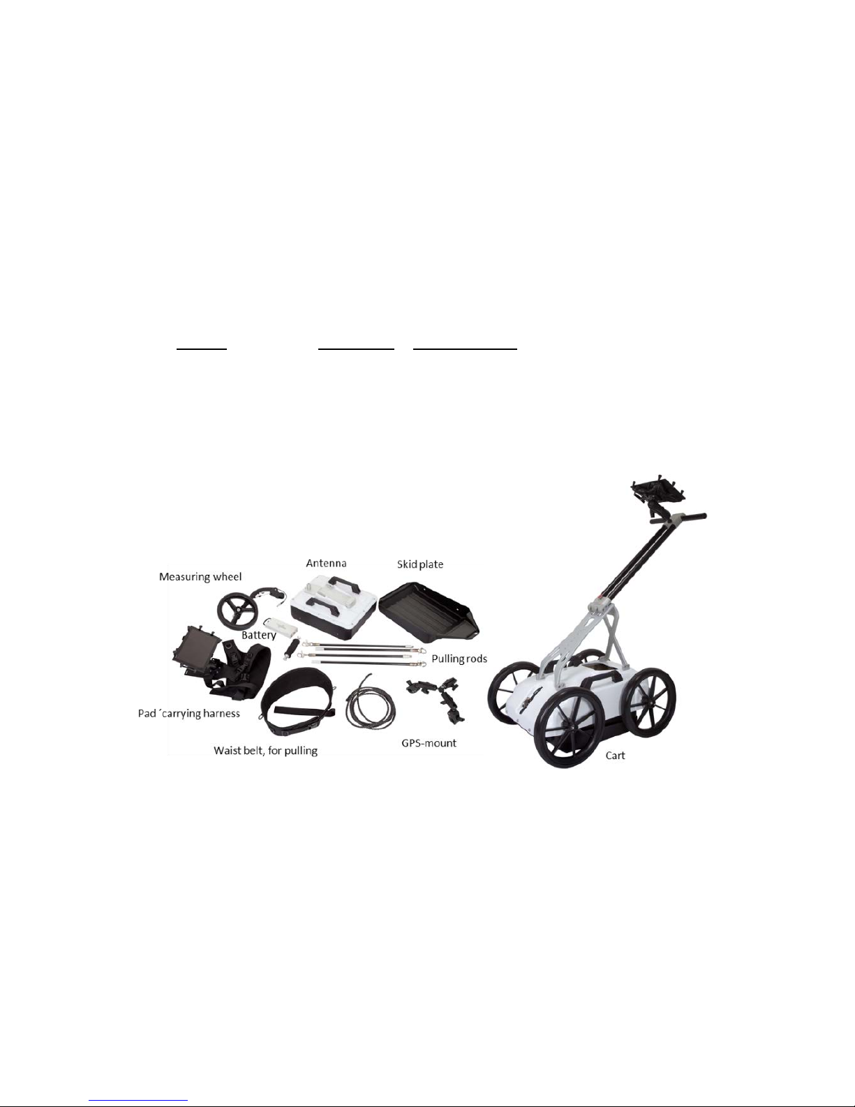
The CrossOver® antennas are supported with a range of accessories that includes push-carts (CO4080
and CO1760 only), pulling kits and external GPS mounts, as shown in Figure 1 below.
Figure 1 System overview
Data collection is managed over a wireless link using a suitable Android device running the CrossOver®
App (CO-App). With the CO-App, the operator may collect single line data, albeit with two frequencies,
or a few different types of multi-line projects. Whether single line of project-based data has been
collected, data-sets may be directly imported into the CrossPoint® Windows software for processing
and evaluation.
Please note that, despite that we recommend quite high-performance devices for data acquisitions,
we regularly use ordinary Android phones for acquisition. This gives some limitations, such as zoom
and direct interpretation, but it is very convenient, in some applications.

ImpulseRadar
CrossOver® User Manual V1.4
Page 5 (31)
For information on other applications and/or configurations, please contact your local ImpulseRadar
representative, or contact our sales team at: sales@impulseradar.se
Antennas
Apart from physical size, CrossOver® antennas share a similar mechanical design and the same
arrangement for the battery, connector panel and measuring wheel mount. A CO4080 antenna is used
to highlight these features, as shown below in Figure 2.
Regardless of model, each Crossover® antenna includes inbuilt WiFi and a high-quality differential GPS
receiver (Ublox/Tallysman). There is no external connection to these components, although markings
on the housing showing their approximate internal location.
Figure 2 CO4080 antenna with battery attached
Connector panel
Refer to the arrangement shown in Figure 2:
• Yellow – Kill switch. In certain countries, a GPR device used on walls should have a kill-switch.
If required, this connector allows the connection of an external kill switch.
• Red – Power and Ethernet. A battery is the preferred way of powering the antenna; however,
an optionable power cable is available upon request. This connector is also used for testing
and factory upgrades via Ethernet.
• Silver – On/Off button. Press the button once for approx. 2s to switch the antenna on. When
on, the button glows blue. A subsequent press will switch the antenna off.
• Blue – External GPS. Allows the connection of an external GPS antenna to provide higher
precision positioning. Communication is based on RS232 and the NMEA 0183, V2, protocol.
• Black – Measuring wheel. Note, this connector is placed further back on the lower frequencies.
All cable-connectors are high-quality Yamaishi-type. Cable-connectors are inserted/removed by
holding the connector sleeve then gently pushing or pulling straight without turning. The connectors
are keyed so that it’s not possible to damage the unit by attaching a cable to the wrong connector.

ImpulseRadar
CrossOver® User Manual V1.4
Page 6 (31)
Battery
CrossOver® antennas are powered via a removeable and rechargeable li-ion battery, which is a nominal
8.7Ah/96.57Wh, providing approximately 7-hours of continuous operation.
Note: ImpulseRadar Li-ion batteries are approved according to UN38.3 and can therefore be safely
carried/shipped by air.
The battery fits securely to the top of the antenna. To insert, position it on the mounting plate and
slide it gently into place, until you hear the locking pin engage (click). To remove, pull the locking pin
out, then gently slide the battery out and off from the mounting plate, Refer to the images in Figure 3
below.
Figure 3 Mounting the battery
Cart
The CO4080 and CO1760 antennas can be used with optional Carts (foldable), as shown below in Figure
4. The push-cart allows the antenna to be manoeuvred easily over a range of surfaces.
Figure 4 CrossOver® Cart (foldable)
ImpulseRadar
CrossOver® User Manual V1.4
Page 7 (31)
The Cart incorporates a break on the rear-right wheel, easily engaged by your foot.
When not in use, the handle mechanism can be folded by removing the M5 retaining screw, as shown
in Figure 4 above. This reduces the overall physical size to facilitate transportation and/or storage.
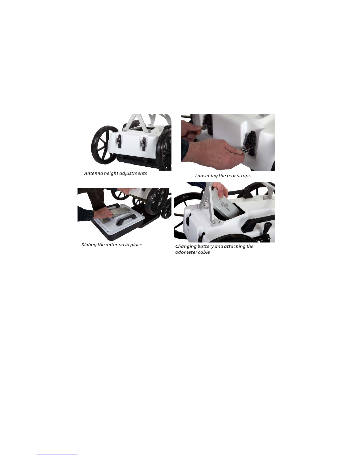
The antenna is mounted into a tray that is connected to the cart-hood by adjustable support straps.
This allows the antenna to be positioned on, or very close, to the ground surface. This arrangement,
as shown in Figure 5 below, allows the antenna to ‘float’ freely vertically and follow the contour of the
ground, or move over bumps and other small obstacles.
Figure 5 Antenna fitting and height adjustments
Antenna fitting procedure, as referenced in Figure 5 above:
1. Remove the rear straps from the snap connectors
2. Lift the cart-hood and slide the antenna into the support tray
3. Connect the odometer cable (black connector)
4. Close the cart-hood and refit the rear straps into the snap connectors
5. Adjust the front and rear straps to obtain the desired height
6. When needed, the battery may be fitted/removed through the opening in the cart-hood
Note: when removing the antenna, remember to disconnect the odometer cable prior to lifting the carthood.
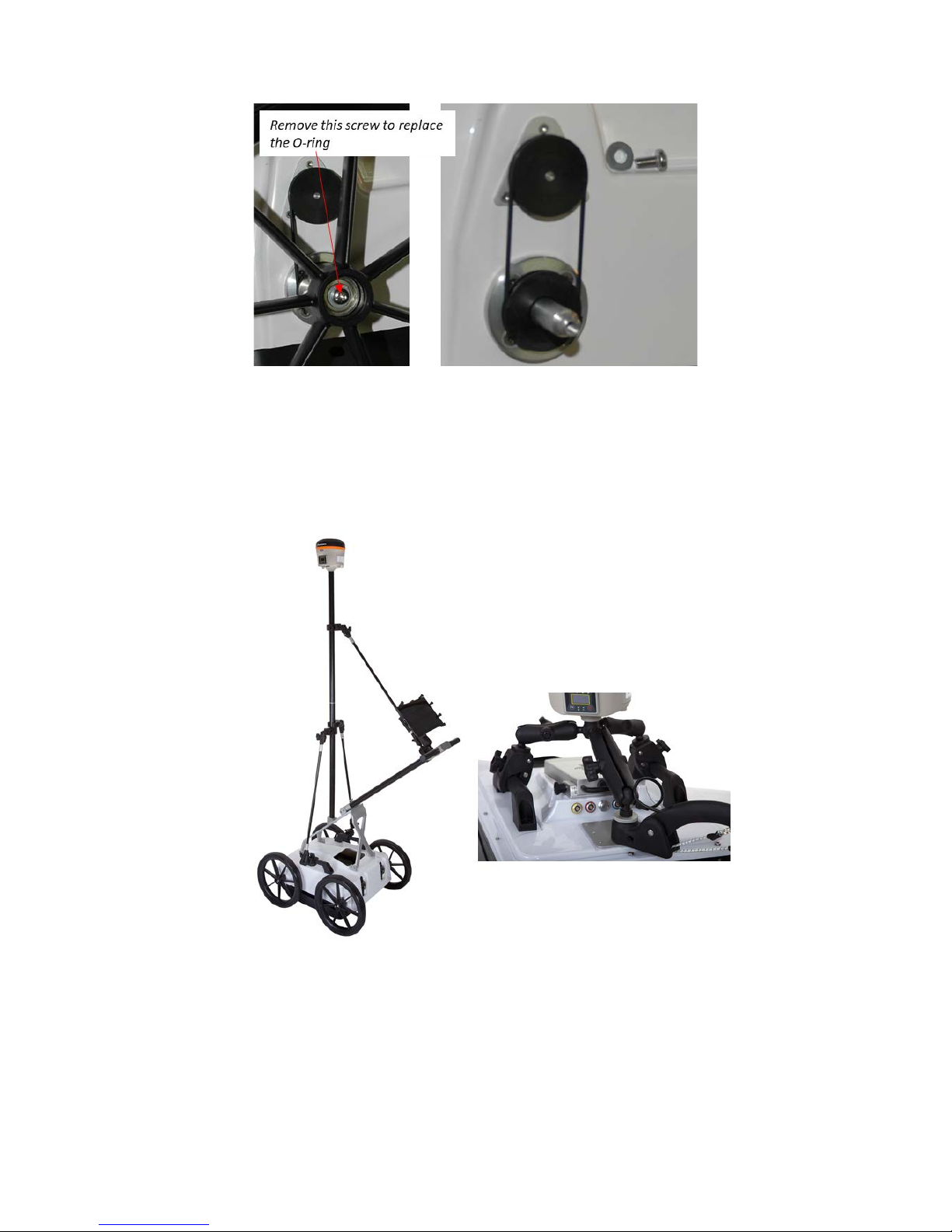
Odometer encoder
To measure distance, the push-cart incorporates an odometer encoder that links to the antenna via
the odometer cable and connector. The encoder itself, is connected to the right-rear wheel by means
of a rubber O-ring. If needed, this O-ring can easily be removed and replaced by first removing the
wheel by unscrewing the M6 retaining screw (as shown in Figure 6 below).
Note: when refitting the wheel, use blue Loctite or equivalent to help secure the M6 retaining screw.
ImpulseRadar
CrossOver® User Manual V1.4
Page 8 (31)
Figure 6 Odometer encoder and wheel assembly
GPS mounts
A range of optional GPS mounting accessories are available for both the push-cart and antenna itself,
as shown below in Figure 7. The mounting poles are available in different lengths to vary the height of
the GPS antenna, as/if needed.
Figure 7 GPS-mounts for the Cart and antennas
ImpulseRadar
CrossOver® User Manual V1.4
Page 9 (31)
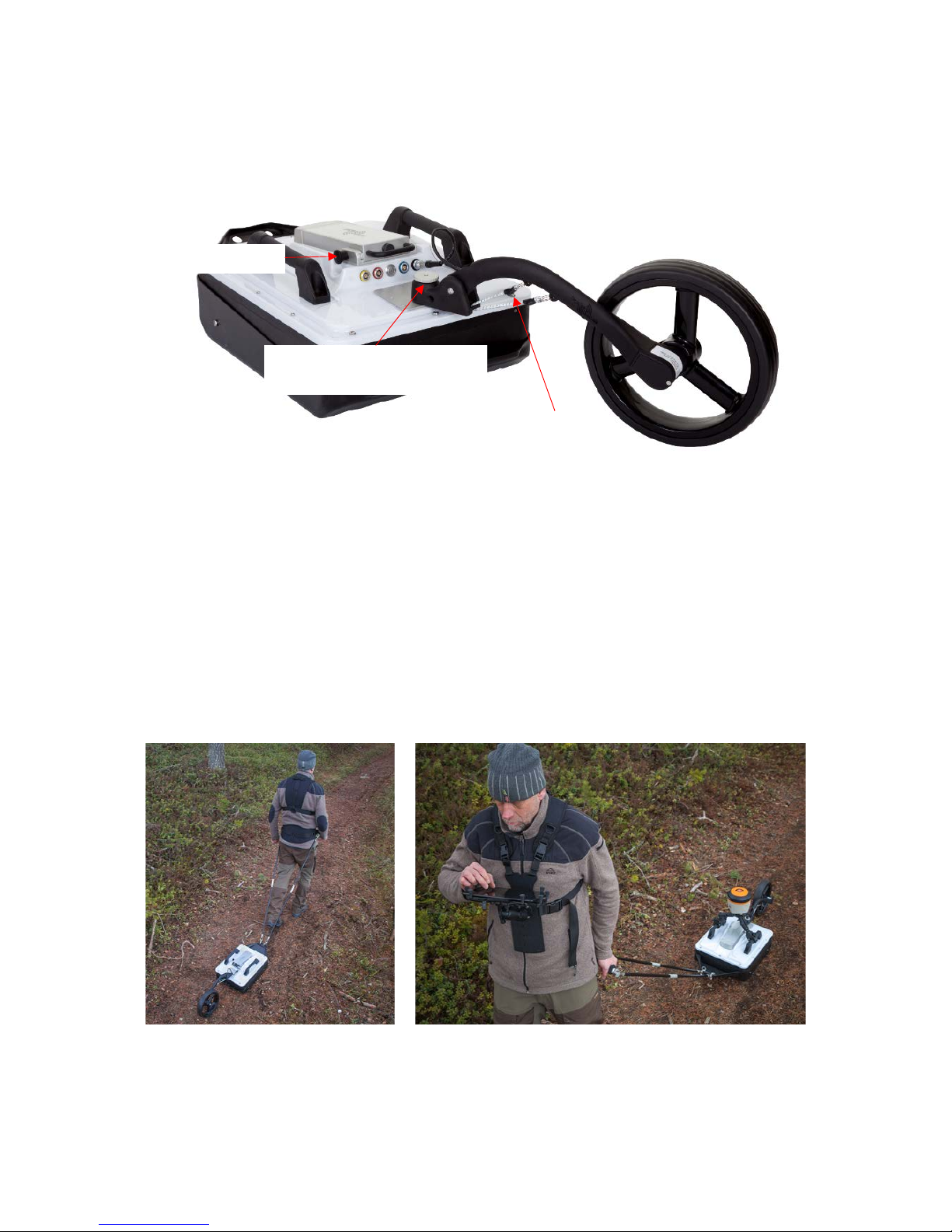
Measuring wheel
Referring to Fel! Hittar inte referenskälla., below. The measuring wheel is made of printed plastics,
the odometer and cable are housed inside, protected. Downward pressure is accomplished with
rubber straps and the shape is optimised for smooth operation, in all cases. Please note that there’s a
threaded hole in the mounting part, for keeping the locking bolt when the wheel is not in use (will help
our clients keep track of the bolt).
Pulling kit
The pulling kit consists of pulling rods, chest-harness, waist belt
These accessories are primarily used in rough terrain, where carts are non-practical, and of course with
the CO730-antenan for which no cart is available, see Figure 9, below.
Figure 9 practical use of the waist belt, pulling rods, handle and pad-harness
Locking bolt
Thread for mounting locking
bolt, when wheel not used
Rubber straps
Figure 8, Measuring wheel attached on antenna

ImpulseRadar
CrossOver® User Manual V1.4
Software
Overview
CrossOver® has been designed to work wirelessly with suitable Android devices running the
CrossOver® App. Refer to Appendix A for a list of specification requirements.
Android devices that meet or exceed the minimum specification requirements will generally offer
better performance in terms of WiFi coverage, data recovery and on-screen functionality. That said,
low-end Android based smartphones can offer a quick and simple means of collecting radar profiles.
Since Android devices are not as standardized as PC’s, there may be slight variations in the way
software is installed and operated between different devices. The following section will detail various
screen shots and menus as taken from a recommended device. However, this may be slightly different
to your personal device.
How to avoid WiFi connection issues
A CrossOver® antenna acts as a wireless access point (WAP) to which your Android device needs to
connect. Once the device has been set-up and connected to the CrossOver® Antenna once, it will then
automatically connect again when within range (if the AP is not disabled (forgotten)).
Nowadays, you are more than likely to have more than one device, and you may in fact like to have
more than one device set-up to collect CrossOver® data. This raises an issue in relation to which device
will connect and stay connected, if more than one is within range; since, this could lead to interruptions
in data acquisition. To manage this, once a CrossOver® antenna is connected to a device, the antenna
cannot be connected to other nearby devices (but these devices can force connection if it is necessary
to change a device).
For users with multiple CrossOver® antennas, we recommend allocating one primary data acquisition
device to each, to avoid the potential issues described above. Furthermore, once the device is
connected, you should disable the AP for any other CrossOver® antennas on that device.
CrossOver® App installation
Security note
As part of the Android operating system, there is a security restriction that prevents the installation of
applications from outside the Google Play Store. Since the CrossOver® App is not yet available on the
Google Play Store, you will need to make some adjustments to your device system settings to proceed
with installation, as follows:
1. Navigate to Settings > Personal > Lock screen and security
2. Check the option "Unknown sources"
3. At the message prompt, select “OK”
You may now proceed with the installation of the CrossOver® App.
The CrossOver® App software is supplied on a USB thumb drive and can either be installed directly
from this device, or by copying it to the internal memory of your Android device. Whichever method
you chose, the installation process is as follows:
 Loading...