

Page 1

SIO-104+2
Users Manual
Part # 3502
Sealevel Systems, Inc. Telephone: 864.843.4343
PO Box 830 Fax: 864.843.3067
Liberty, SC 29657 USA www.sealevel.com
Page 2

Contents
INTRODUCTION .......................................................................................................................................................1
OVERVIEW .................................................................................................................................................1
WHAT’S INCLUDED....................................................................................................................................1
OPTIONAL ACCESSORIES............................................................................................................................1
CARD SETUP............................................................................................................................................................ 2
SWITCHES SW1A AND SW2A ...................................................................................................................2
Address Selection...................................................................................................................................2
Port Enable / Disable..............................................................................................................................2
INTERRUPT MODES ....................................................................................................................................3
HEADERS E1 AND E2 (IRQ SELECTION)....................................................................................................3
SWITCHES SW1B AND SW2B.................................................................................................................... 4
RS-485 Enable Modes (SW1B and SW2B position 1) .......................................................................... 4
Electrical Interface Selection (Positions 2 and 3)...................................................................................4
Line Termination (Position 4-9).............................................................................................................5
Typical settings for SW1B and SW2B...................................................................................................5
CLOCK MODES...........................................................................................................................................5
INSTALLATION ........................................................................................................................................................6
OPERATING SYSTEM INSTALLATION ..........................................................................................................6
Windows 95/98/ME/NT/2000/XP..........................................................................................................6
Linux ......................................................................................................................................................7
QNX....................................................................................................................................................... 7
PHYSICAL INSTALLATION........................................................................................................................... 7
TECHNICAL DESCRIPTION......................................................................................................................................8
FEATURES .................................................................................................................................................. 8
CONNECTOR PIN ASSIGNMENTS.................................................................................................................8
RS-232....................................................................................................................................................8
RS-422/485.............................................................................................................................................8
SPECIFICATIONS......................................................................................................................................................9
ENVIRONMENTAL SPECIFICATIONS ............................................................................................................9
MANUFACTURING ...................................................................................................................................... 9
POWER CONSUMPTION...............................................................................................................................9
PHYSICAL DIMENSIONS..............................................................................................................................9
APPENDIX A - TROUBLESHOOTING...................................................................................................................... 10
APPENDIX B - HOW TO GET ASSISTANCE ........................................................................................................... 11
APPENDIX C - ELECTRICAL INTERFACE.............................................................................................................. 12
RS-232 .................................................................................................................................................... 12
RS-422 .................................................................................................................................................... 12
RS-485 .................................................................................................................................................... 12
APPENDIX D - ASYNCHRONOUS COMMUNICATIONS ........................................................................................... 13
APPENDIX E - PC/104...........................................................................................................................................14
WHAT IS PC/104? ....................................................................................................................................14
APPENDIX F - SILK-SCREEN................................................................................................................................. 15
WARRANTY ...........................................................................................................................................................16
©Sealevel Systems Inc.
SL9116 Revision 7/2006
Sealevel Systems, Incorporated. All rights reserved.
Page 3

Introduction
Introduction
Overview
The SIO-104+2 series provides the ultimate serial connection for your PC/104 application. The SIO-104+2 when
configured in the RS-422/485 mode provides an interface capable of long length, high-speed communications, or
when configured in the RS-232 mode provides a standard RS-232C interface that is fully compatible all popular
modem software, network operating systems software, and mouse drivers.
What’s Included
The SIO-104+2 is shipped with the following items. If any of these items are missing or damaged, contact the
supplier.
• (1) SIO-104+2 Serial Interface Adapter
• (1) Nylon Mounting Hardware Kit (PC304-NK)
• Sealevel Systems Software
Optional Accessories
• CA152 - Terminates the SIO-104+2 10 pin header to a DB9M connector.. This cable provides the standard
DB9 pin out for RS-232 (aka EIA/TIA574) and also provides the Sealevel Systems’ DB9 standard for RS422/485.
• DB103 - The DB103 is designed to convert a Sealevel DB9 Male connector to a pinout compatible with
AC24AT and AC422AT Opto-22 ISA bus cards. When used with the optional CA152 cable assembly it
allows Optomux devices to be controlled with the SIO-104+2.
• CA190 - When used with the optional CA152 cable assembly it allows connection directly to a Sony (or
compatible) 207M "9 Pin" connector.
Sealevel Systems SIO-104+2 Page 1
Page 4
Card Setup
Card Setup
The SIO-104+2 contains two DIP-Switches and a jumper strap for each port, which must be set for proper
operation.
Switches SW1A and SW2A
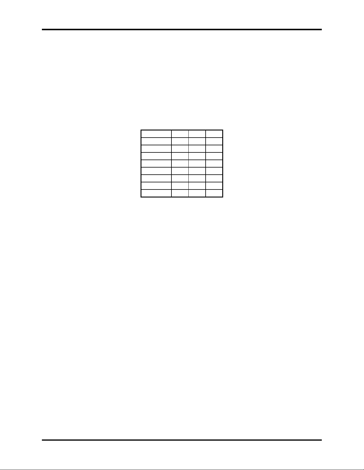
Address Selection
Each port on the SIO-104+2 occupies eight consecutive I/O locations. A DIP-switch is used to set the base address
for these locations. SW1A sets the I/O address for port 1 and SW2A sets port 2. The following table shows the
addressing options available. If different address options are required, please contact Sealevel Systems Technical
Support about a custom PAL option.
1 2 3
3F8 On On On
2F8 On On Off
3E8 On Off On
2E8 On Off Off
2A0 Off On On
300 Off On Off
328 Off Off On
Disabled Off Off Off
Figure 1 - Address Selection Table
Note: Each COM: port in the system should have a unique address. Typically COM1: - COM4: addresses are 3F8,
2F8, 3E8 and 2E8 Hex.
Refer to Appendix A for common address contentions.
Port Enable / Disable
Each port on the SIO-104+2 can be enabled or disabled by setting the three switches in the ‘Off’ position. The port
is enabled when a valid I/O selection is made. If any port is disabled, be sure to disable the interrupt request for that
port by removing the IRQ jumper.
Sealevel Systems SIO-104+2 Page 2
Page 5
Card Setup
Interrupt Modes
DIP-Switch positions ‘S’ and ‘M’ on switches SW1A and SW2A select the interrupt mode for each port. Each port
must be set in the correct mode to insure proper operation.
With the ‘S’ selected, the adapter is in a (S)hared interrupt mode, which allows more than one port to access a single
IRQ. Any two or more ports can share a common IRQ by placing the jumpers on the same IRQ setting and setting
the appropriate selections at E1and E2.
‘M’ indicates the inclusion of a 1K-ohm pull-down resistor required on one port when sharing interrupts.
Set the switch to ‘S’ for shared interrupt mode on all ports sharing an IRQ. On one of the ports sharing an interrupt
set the switches for both ‘S’ and for ‘M’. This provides the pull-down resistor circuit that makes sharing IRQs
possible. If you are using more than one compatible adapter in a bus you should only have one port set to ‘M’.
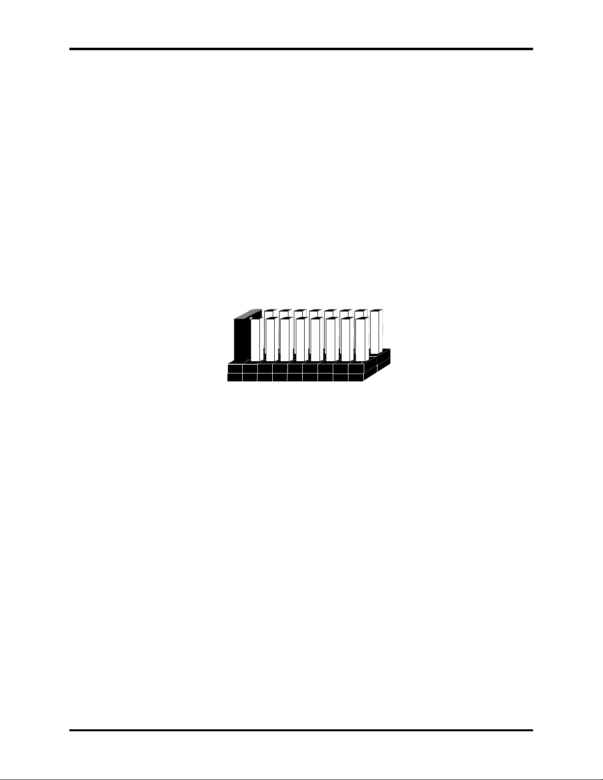
Headers E1 and E2 (IRQ Selection)
The SIO-104+2 has two interrupt selection jumpers, which should be set prior to use, if an interrupt is required by
your application software. Consult the user manual for the application software being used to determine the proper
setting.
3 4 5 7 9 10111215
Figure 2 - Header E1 and E2, IRQ Selection (IRQ 3 shown selected)
Any two or more ports can share a common IRQ by placing the jumpers on the same IRQ setting at header E1 and
E1 and setting the appropriate selections at SW1A and SW2A.
Sealevel Systems SIO-104+2 Page 3
Page 6
Card Setup
Switches SW1B and SW2B
RS-485 Enable Modes (SW1B and SW2B position 1)
RS-485 is ideal for multi-drop or network environments. RS-485 requires a tri-state driver that will allow the
electrical presence of the driver to be removed from the line. The driver is in a tri-state or high impedance condition
when this occurs. Only one driver may be active at a time and the other driver(s) must be tri-stated. The output
modem control signal Request To Send (RTS) is typically used to control the state of the driver. Some
communication software packages refer to RS-485 as RTS enable or RTS block mode transfer.
One of the unique features of the SIO-104+2 is the ability to be RS-485 compatible without the need for special
software or drivers. This ability is especially useful in Windows, Windows NT, and OS/2 environments where the
lower level I/O control is abstracted from the applicatio n program. This ability means that the user can effectively
use the SIO-104+2 in an RS-485 application with existing (i.e. standard RS-232) software drivers.
DIP-Switch SW2A and SW2B are used to control the RS-485 mode functions for the driver circuit. The selections
are:
‘Auto’ enable (Switch position 1 ‘Off’). The ‘Auto’ enable feature automatically enables/disables the RS-485
interface via on board circuitry.
‘RTS’ enable (Switch position 1 ‘On’) The ‘RTS’ mode uses the ‘RTS’ modem control signal to enable the RS-485
interface and provides backward compatibility with existing software products.
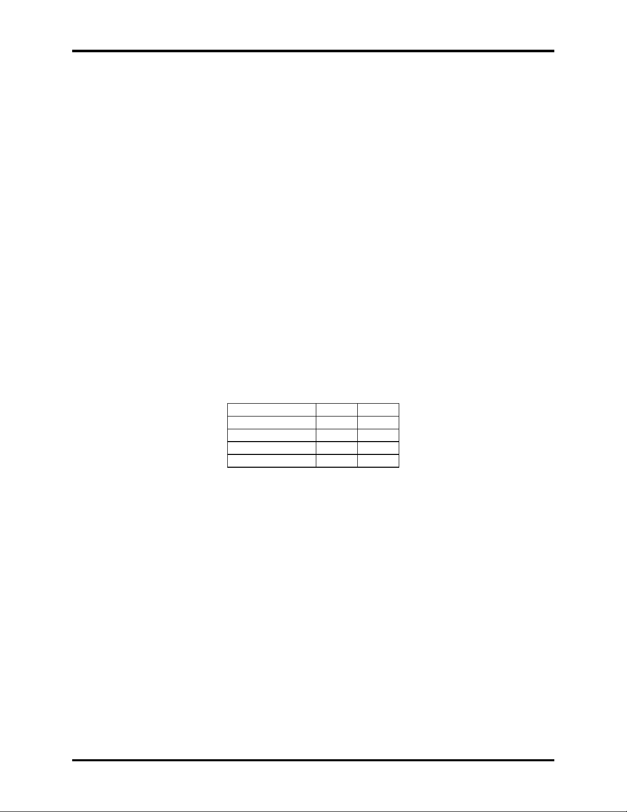
Electrical Interface Selection (Positions 2 and 3)
Positions 2 and 3 select the Electrical Interface for the SIO-104+2, the following table represents the only valid
options:
Mode M0 M1
RS232 OFF OFF
RS422 OFF ON
RS485 with echo ON OFF
RS485 no echo ON ON
Sealevel Systems SIO-104+2 Page 4
Page 7

Card Setup
Line Termination (Position 4-9)
Typically, each end of the RS-485 bus must have line-terminating resistors (RS-422 terminates at the receive end
only). A 120-ohm resistor is across each RS-422/485 input in addition to a 1K-ohm pull-up/pull-down combination
that biases the receiver inputs. Switches SW1B and SW2B allows customization of this interface to specific
requirements. Each jumper position corresponds to a specific portion of the interface. If multiple SIO-104+2
adapters are configured in a RS-485 network, only the boards on each end should have jumpers T, P & P ON. Refer
to the following table for each position’s operation:
Name Function
PD Adds or removes the 1K ohm pull-down resistor in the RS-422/RS-485 receiver circuit (Receive data
only).
PU Adds or removes the 1K ohm pull-up resistor in the RS-422/RS-485 receiver circuit (Receive data only).
BS Use only for RS-422/485
T Adds or removes the 120 ohm termination.
L Connects the TX+ to RX+ for RS-485 two-wire operation.
L Connects the TX- to RX- for RS-485 two-wire operation.
Typical settings for SW1B and SW2B
Mode
M0 (2) M1 (3) PD (4) PU (5) BS (6) T (7) L (8) L (9)
(Switch position)
RS232 OFF OFF OFF OFF OFF OFF OFF OFF
RS422 OFF ON ON ON ON ON OFF OFF
RS485 with echo ON OFF ON ON ON ON* OFF OFF
RS485 no echo ON ON ON ON ON ON* ON ON
* If at end of RS485 bus turn termination ON
If in middle leave OFF
Clock Modes
The SIO-104+2 employs a 7.3728 MHz clock. This provides for data rates up to 460.8Kbps.
Sealevel Systems SIO-104+2 Page 5
Page 8

Installation
Installation
Operating System Installation
Windows 95/98/ME/NT/2000/XP
Do not install the adapter in the machine until the software has been fully installed.
1. Start Windows.
2. Insert the Sealevel Systems CD in to your CD drive.
3. If ‘Auto-Start’ is enabled for this drive the software will automatically launch.
4. Otherwise, point your browser to the ‘Index.htm’ on the root directory of the CD
5. The next step is to select ‘Install Software’.
6. Select the Part Number for your adapter from the listing.
7. Select ‘Windows 95/98/ME/NT/2000/XP’ then (depending on the OS version) select the ‘Run from current
Location’ or ‘Open’ option. Follow the information presented on the screens that follow.
8. Run the Add/Remove Hardware utility located in Control Panel. Double click the icon to launch the
Wizard. When the Choose Hardware Task appears choose Add/Troubleshoot a device. At that point
Windows will search for Plug and Play devices. Since the ISA board is not Plug and Play it will not be
found. If Windows finds something you were not expecting, cancel that install and click Next. When
Choose a Hardware Device appears select Add a new device. Windows will then ask if you want it to
search and you select No, I want to select the hardware from a list. Then click Next. After choosing Next
you will see Hardware Type. If you are installing a single port serial card select Ports (COM & LPT). If
you are installing a multiport serial card, (two or more ports), choose Multi-port serial adapters. Click
Next. The Select a Device Driver window will appear. On the left side find Sealevel Systems, Inc. and on
the right side of the window select the card type you are installing.
9. Windows will now show a warning message that it could not detect the settings of the device and that you
must enter the settings manually. Click OK. The Add New Hardware Wizard Properties window will
appear. This window will show the default settings for the I/O address and one IRQ. The one IRQ will
mean that you will be sharing one IRQ for all ports on the board for a multi port card. You will only need
one IRQ if installing a single port card. Since Windows cannot detect the settings there my be a conflict
with another device or the settings shown may be not the settings you wish to use. To change the settings
choose Basic configuration 0001 next to the heading Setting based on:. When this configuration is chosen
the Resources window will appear with all question marks. Simply choose each Input/Output Range and
IRQ and change the settings to match the board settings. Make sure there are no conflicts with other
devices that would appear at the bottom of the window under Conflicting device list. After you have either
accepted the default settings or changed the settings, the Start Hardware Installation window will appear.
Click Next.
10. The next window that may appear will be the Digital Signature Not Found. Do not search for digitally
signed software and continue with the installation. The Completing the Add/Remove Hardware Wizard
window will appear. You will be given a chance to change the resource settings again at this point if
necessary. Choose Finish. At this point you will need to restart your computer. After restarting the Found
New Hardware window will appear for each port that you are installing. To confirm that the drivers
installed you can now look in Device Manager under Ports (COM &LPT) and each of the ports should
show with their corresponding COM number.
Sealevel Systems SIO-104+2 Page 6
Page 9

Installation
Linux
Refer to D:\software\seacom\Other\Linux\Linux.serial.readme (where D: = your CDROM driver letter) found on
the Sealevel Systems CD. This file contains valuable information on installing your adapter in the various Linux
releases. Also in this sub-directory is the Linux SerialHOWTO. This series of files explains typical Linux serial
implementations, as well as informing the user to Linux syntax and preferred practices.
QNX
Refer to D:\software\seacom\Other\QNX6\Install.readme (where D: = your CDROM driver letter) found on the
Sealevel Systems CD. This file contains valuable information on installing your adapter in the QNX6 Neutrino OS,
as well as the files required to ensure a flawless implementation. Also provided on the Sealevel Systems CD are
implementation instructions for QNX4. These are found in D:\software\seacom\Other\QNX4\QNX_COM.txt.
Physical Installation
Extreme care should be taken when installing the adapter to avoid causing damage to the connectors. After the
adapter is installed, connect your I/O cables. Please note these headers are keyed so that pin 1 of the cable matches
pin 1 of the connector. Refer to Card Setup for information on setting the address and IRQ before inserting the
adapter onto the stack.
1. Turn off PC power. Disconnect the power cord.
2. Remove the case cover (if applicable).
3. Gently insert the adapter noting proper key orientation of the expansion connector on a PC/104 compatible
card. The adapter is keyed per the current PC/104 Specification. This will aid in preventing the adapter
from being inserted incorrectly.
4. Mounting hardware (nylon stand-offs and screws) is provided to ensure a good mechanical connection.
Retain any mounting hardware not used to allow for future expansion.
5. The cables provided are keyed and can be installed before or after the adapter is inserted in the stack.
6. Replace the cover.
7. Connect the power cord and power up the machine.
Sealevel Systems SIO-104+2 Page 7
Page 10

Technical Description
Technical Description
The SIO-104+2 series provides the ultimate serial connection for your PC/104 application. SIO-104+2 utilizes the
16850 UART. These chip features programmable baud rates, data format, interrupt control and 128 Byte input and
output FIFOs.
The SIO-104+2 when configured with the RS-422/485 interface will allow long length, high-speed communications
suitable for data collection and shop floor control.
The SIO-104+2 when configured with the RS-232C interface, is fully compatible with the DOS operating system,
all popular modem software, network operating systems software, and mouse drivers.
Features
• Selectable interrupts (IRQs) 3, 4, 5, 7, 9, 10, 11, 12, 15
• Multiple adapters can share the same IRQ
• Uses PC/104 compatible stack through connector for universal mounting
• 5 volt only DC operation
Connector Pin Assignments
RS-232
Signal Name J1/J2 DB-9 Mode
GND Ground 9 5
TD Transmit Data 5 3 Output
RTS Request To Send 4 7 Output
DTR Data Terminal Ready 7 4 Output
RD Receive Data 3 2 Input
CTS Clear To Send 6 8 Input
DSR Data Set Ready 2 6 Input
CD Carrier Detect 1 1 Input
RI Ring Indicator 8 9 Input
Note: These assignments meet EIA/TIA/ANSI-574 DTE for DB-9 type connectors.
RS-422/485
Signal Name Pin # Mode
GND Ground 9 5
TX + Transmit Data Positive 7 4 Output
TX- Transmit Data Negative 5 3 Output
RTS+ Request to Send Positive 2 6 Output
RTS- Request to Send Negative 4 7 Output
RX+ Receive Data Positive 1 1 Input
RX- Receive Data Negative 3 2 Input
CTS+ Clear to Send Positive 8 9 Input
CTS- Clear to Send Negative 6 8 Input
Technical Note: Please terminate any control signals that are not going to be used. The most common way to do this
is connect RTS to CTS and RI. Also, con nect DCD to DTR and DSR. Terminating these pins, if no t used, will help
insure you get the best performance from your adapter.
Sealevel Systems SIO-104+2 Page 8
Page 11

Specifications
Specifications
Environmental Specifications
Specification Operating Storage
Temperature
Range
Humidity Range
Manufacturing
All Sealevel Systems Printed Circuit boards are built to UL 94V0 rating and are 100% electrically tested. These
printed circuit boards are solder mask over bare copper or solder mask over tin nickel.
Power Consumption
Physical Dimensions
Board Length 3.550 inches (9.017 cm.)
Board Height 3.775 inches (9.589 cm.)
0º to 70º C
(32º to 158º F)
10 to 90% R.H.
Non-Condensing
Supply line
Rating
+5VDC
220 mA
-50º to 105º C
(-58º to 221º F)
10 to 90% R.H.
Non-Condensing
Sealevel Systems SIO-104+2 Page 9
Page 12

Appendix A - Troubleshooting
Appendix A - T roubleshooting
1. Iden tify all I/O adapters currently installed in your system. This includes your on-board serial ports, controller
cards, sound cards etc. The I/O addresses used by these adapters, as well as the IRQ (if any) should be
identified.
2. Configure your Sealevel Systems adapter so that there is no conflict with cu rrently installed adapters. No two
adapters can occupy the same I/O address.
3. Try the Sealevel Systems adapter with a unique IRQ. While the Sealevel Systems adapter does allow the
sharing of IRQs, many other adapters (i.e. SCSI adapters & on-board serial ports) do not
4. Make sure the Sealevel Systems adapter is securely installed.
5. For Windows95/98/ME/NT/2000, the diagnostic tool ‘WinSSD’ is installed in the SeaCOM folder on the Start
Menu during the setup process. First find the ports using the Device Manager, then use ‘WinSSD’ to verify that
the ports are functional.
6. Remember if a “No Echo” mode is selected, a data loopback cannot be accomplished.
7. Always use the Sealevel Systems diagnostic software when troubleshooting a problem. This will eliminate any
software issues from the equation.
.
Sealevel Systems SIO-104+2 Page 10
Page 13

Appendix B - How To Get Assistance
Appendix B - How To Get Assistance
Please refer to Troubleshooting Guide prior to calling Technical Support.
1. Begin by reading through the Trouble Shooting Guide in Appendix A. If assistance is still needed
please see below.
2. When calling for technical assistance, please have your user manual and current adapter settings. If
possible, please have the adapter installed in a computer ready to run diagnostics.
3. Sealevel Systems provides an FAQ section on its web site. Please refer to this to answer many
common questions. This section can be found at http://www.sealevel.com/faq.asp
.
4. Sealevel Systems maintains a web page on the Internet. Our home page address is www.sealevel.com
The latest software updates, and newest manuals are available via our web site.
5. Technical support is available Monday to Friday from 8:00 a.m. to 5:00 p.m. eastern time. Technical
support can be reached at (864) 843-4343.
Return Authorization Must Be Obtained From Sealevel Systems Before Returned Merchandise Will Be
Accepted. Authorization Can Be Obtained By Calling Sealevel Systems And Requesting A Return
Merchandise Authorization (RMA) Number.
.
Sealevel Systems SIO-104+2 Page 11
Page 14

Appendix C - Electrical Interface
Appendix C - Electrical Interface
RS-232
Quite possibly the most widely used communication standard is RS-232. This implementation has been defined and
revised several times and is often referred to as RS-232-C/D/E or EIA/TIA-232-C/D/E. It is defined as “Interface
between Data Terminal Equipment and Data Circuit- Terminating Equipment Employing Serial Binary Data
Interchange”. The mechanical implementation of RS-232 is on a 25-pin D sub connector. The IBM PC computer
defined the RS-232 port on a 9 pin D sub connector and subsequently the EIA/TIA approved this implementation as
the EIA/TIA-574 standard. This standard has defined as the “9-Position Non-Synchronous Interface between Data
Terminal Equipment and Data Circuit-Terminating Equipment Employing Serial Binary Data Interchange”. Both
implementations are in wide spread use and will be referred to as RS-232 in this document. RS-232 is capable of
operating at data rates up to 20K bps / 50 ft. The absolute maximum data rate may vary due to line conditions and
cable lengths. RS-232 often operates at 38.4K bps over very short distances. The voltage levels defined by RS-232
range from -12 to +12 volts. RS-232 is a single ended or unbalanced interface, meaning that a single electrical
signal is compared to a common signal (ground) to determine binary logic states. A voltage of +12 volts (usually +3
to +10 volts) represents a binary 0 (space) and -12 volts (-3 to -10 volts) denote a binary 1 (mark). The RS-232 and
the EIA/TIA-574 specification define two types of interface circuits Data Terminal Equipment (DTE) and Data
Circuit-Terminating Equipment (DCE). The Sealevel Systems Adapter is a DTE interface.
RS-422
The RS-422 specification defines the electrical characteristics of balanced voltage digital interface circuits. RS-422
is a differential interface that defines voltage levels and driver/receiver electrical specifications. On a differential
interface, logic levels are defined by the difference in voltage between a pair of outputs or inputs. In contrast, a
single ended interface, for example RS-232, defines the logic levels as the difference in voltage between a single
signal and a common ground connection. Differential interfaces are typically more immune to noise or voltage
spikes that may occur on the communication lines. Differential interfaces also have greater drive capabilities that
allow for longer cable lengths. RS-422 is rated up to 10 Megabits per second and can have cabling 4000 feet long.
RS-422 also defines driver and receiver electrical characteristics that will allow 1 driver and up to 32 receivers on
the line at once. RS-422 signal levels range from 0 to +5 volts. RS-422 does not define a physical connector.
RS-485
RS-485 is backwardly compatible with RS-422; however, it is optimized for party line or multi-drop applications.
The output of the RS-422/485 driver is capable of being Active (enabled) or Tri-State (disabled). This capability
allows multiple ports to be connected in a multi-drop bus and selectively polled. RS-485 allows cable lengths up to
4000 feet and data rates up to 10 Megabits per second. The signal levels for RS-485 are the same as those defined
by RS-422. RS-485 has electrical characteristics that allow for 32 drivers and 32 receivers to be connected to one
line. This interface is ideal for multi-drop or network environments. RS-485 tri-state driver (not dual-state) will
allow the electrical presence of the driver to be removed from the line. Only one driver may be active at a time and
the other driver(s) must be tri-stated. RS-485 can be cabled in two ways, two wire and four wire mode. Two-wire
mode does not allow for full duplex communication, and requires that data be transferred in only one direction at a
time. For half-duplex operation, the two transmit pins should be connected to the two receive pins (Tx+ to Rx+ and
Tx- to Rx-). Four wire mode allows full duplex data transfers. RS-485 does not define a connector pin-out or a set
of modem control signals. RS-485 does not define a physical connector.
Sealevel Systems SIO-104+2 Page 12
Page 15

Appendix C - Electrical Interface
r
Appendix D - Asynchronous Communications
Serial data communications implies that individual bits of a character are transmitted consecutively to a receiver that
assembles the bits back into a character. Data rate, error checking, handshaking, and character framing (start/stop
bits) are pre-defined and must correspond at both the transmitting and receiving ends.
Asynchronous communications is the standard means of serial data communication for PC compatibles and PS/2
computers. The original PC was equipped with a communication or COM: port that was designed around an 8250
Universal Asynchronous Receiver Transmitter (UART). This device allows asynchronous serial data to be
transferred through a simple and straightforward programming interface. A starting bit followed by a pre-defined
number of data bits (5, 6, 7, or 8) defines character boundaries for asynchronous communications. The end of the
character is defined by the transmission of a pre-defined number of stop bits (usually 1, 1.5 or 2). An extra bit used
for error detection is often appended before the stop bits.
Idle state of
line
1
0
5 to 8 Data Bits
Figure 3 - Asynchronous Communications Bit Diagram
This special bit is called the parity bit. Parity is a simple method of determining if a data bit has been lost or
corrupted during transmission. There are several methods for implementing a parity check to guard against data
corruption. Common methods are called (E)ven Parity or (O)dd Parity. Sometimes parity is not used to detect errors
on the data stream. This is refereed to as (N)o parity. Because each bit in asynchronous communications is sent
consecutively, it is easy to generalize asynchronous communications by stating that each character is wrapped
(framed) by pre-defined bits to mark the beginning and end of the serial transmission of the character. The data rate
and communication parameters for asynchronous communications have to be the same at both the transmitting and
receiving ends. The communication parameters are baud rate, parity, number of data bits per character, and stop bits
(i.e. 9600,N,8,1).
Odd, Even
or
Unused
P
BIT
STOP
Remain Idle o
next start bit
1
1.5
2
Sealevel Systems SIO-104+2 Page 13
Page 16

Appendix E - PC/104
Appendix E - PC/104
What is PC/104?
The PC has become extremely popular in both general purpose (desktop) and dedicated (embedded) applications.
Unfortunately the PC has been hampered by the large size required to maintain PC compatibility. PC/104 addresses
this by optimizing the PC bus in a form factor designed for embedded applications.
Briefly, the key differences between PC/104 and the standard “AT” or ISA bus computer are as follows:
• Reducing the form factor, to 3.550 by 3.775 inches
• Eliminating the need for backplanes or card cages, through its self-stacking bus
• Minimizing component count and power consumption (typically 1-2 Watts per module) by reducing required
bus drive on most signals to 4 mA.
Sealevel Systems has been a member of the PC/104 Consortium since its inception. Also Sealevel Systems has two
members on the working group that is currently having the PC/104 bus approved by the IEEE as P996.1.
Questions about the PC/104 Consortium can be sent to:
PC/104 Consortium
P. O. Box 4303
Mountain View, CA 94040
(415) 903-8304 Ph. (415) 967-0995 Fax
www.controlled.com/pc104
Sealevel Systems SIO-104+2 Page 14
Page 17

Appendix F - Silk-Screen
Appendix F - Silk -Screen
Sealevel Systems SIO-104+2 Page 15
Page 18

Warranty
Warranty
Sealevel's commitment to providing the best I/O solutions is reflected in the Lifetime
Warranty that is standard on all Sealevel manufactured products. We are able to offer
this warranty due to our control of manufacturing quality and the historically high
reliability of our products in the field. Sealevel products are designed and
manufactured at its Liberty, South Carolina facility, allowing direct control over
product development, production, burn-in and testing.
Sealevel Systems, Inc. (hereafter "Sealevel") warrants that the Product shall conform to and perform in accordance
with published technical specifications and shall be free of defects in materials and workmanship for life. In the
event of failure, Sealevel will repair or replace the product at Sealevel's sole discretion. Failures resulting from
misapplication or misuse of the Product, failure to adhere to any specifications or instructions, or failure resulting
from neglect or abuse are not covered under this warranty.
Warranty service is obtained by delivering the Product to Sealevel and providing proof of purchase. Return
authorization must be obtained from Sealevel Systems before returned merchandise will be accepted.
Authorization is obtained by calling Sealevel Systems and requesting a Return Merchandise Authorization
(RMA) number. The Customer agrees to insure the Product or assume the risk of loss or damage in transit, to
prepay shipping charges to Sealevel, and to use the original shipping container or equivalent. Warranty is valid only
for original purchaser and is not transferable.
Sealevel Systems assumes no liability for any damages, lost profits, lost savings or any other incidental or
consequential damage resulting from the use, misuse of, or inability to use this product. Sealevel Systems will not
be liable for any claim made by any other related party.
This warranty applies to Sealevel manufactured Product. Product purchased through Sealevel but manufactured by a
third party will retain the original manufacturer's warranty.
Sealevel Systems, Incorporated
2779 Greenville Highway
P.O. Box 830
Liberty, SC 29657 USA
(864) 843-4343 FAX: (864) 843-3067
www.sealevel.com
email: support@sealevel.com
Technical Support is available from 8 a.m. to 5 p.m. Eastern time.
Monday - Friday
Trademarks
Sealevel Systems, Incorporated acknowledges that all trademarks referenced in this manual are the service mark,
trademark, or registered trademark of the respective company.
SIO-104+2 is a trademark of Sealevel Systems, Incorporated.
Sealevel Systems SIO-104+2 Page 16
 Loading...