

Page 1
SensorLex 8B Isolated Analog Signal Conditioning Products
▲
Accessories for 8B Analog Modules
▲
Features
2-, 4-, 8-, 16-Position Backpanels
19-Inch Mounting Rack For Backpanels
Interface Cables
8BP02, 8BP04, 8BP08, 8BP16
2-, 4-, 8-, and 16-Position Analog I/O Backpanels
Description
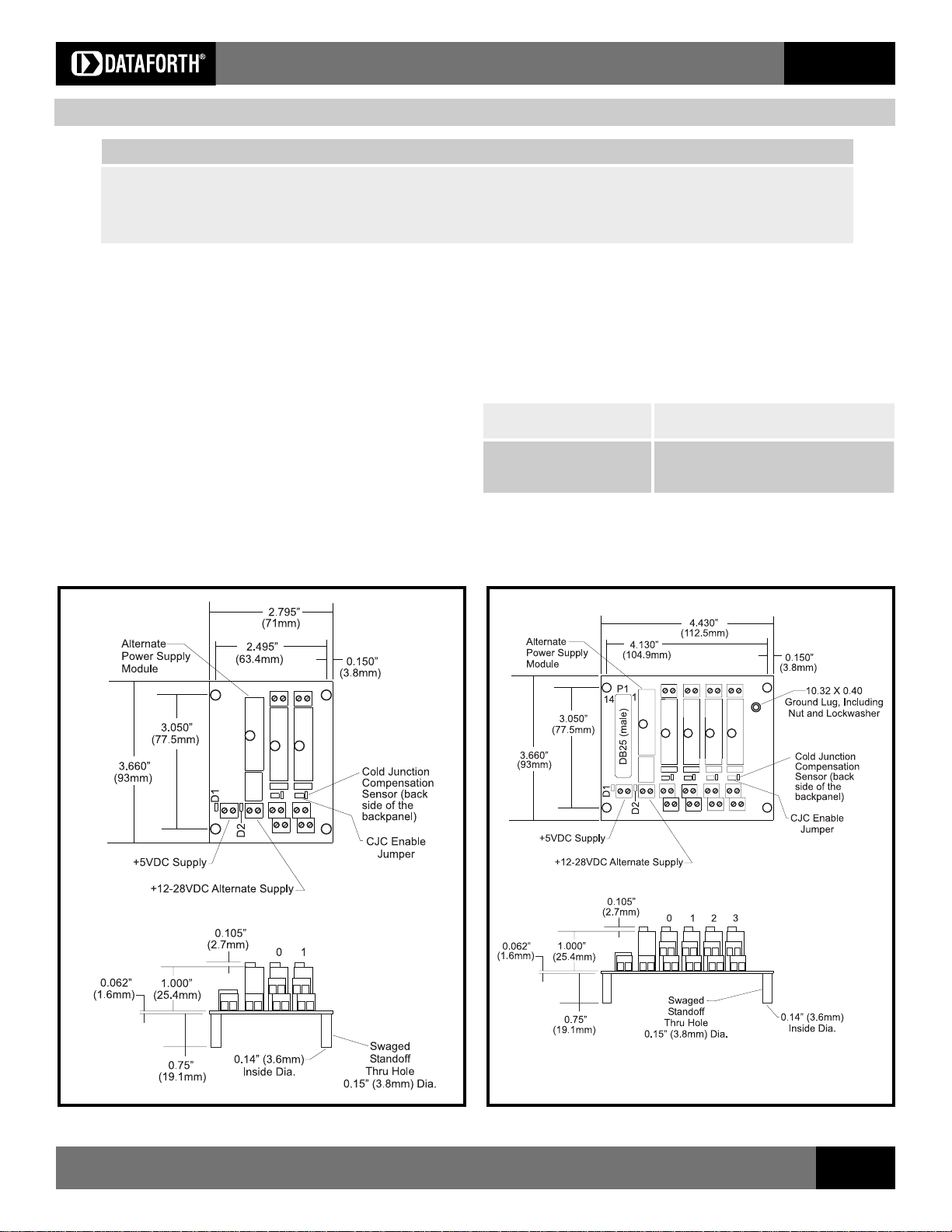
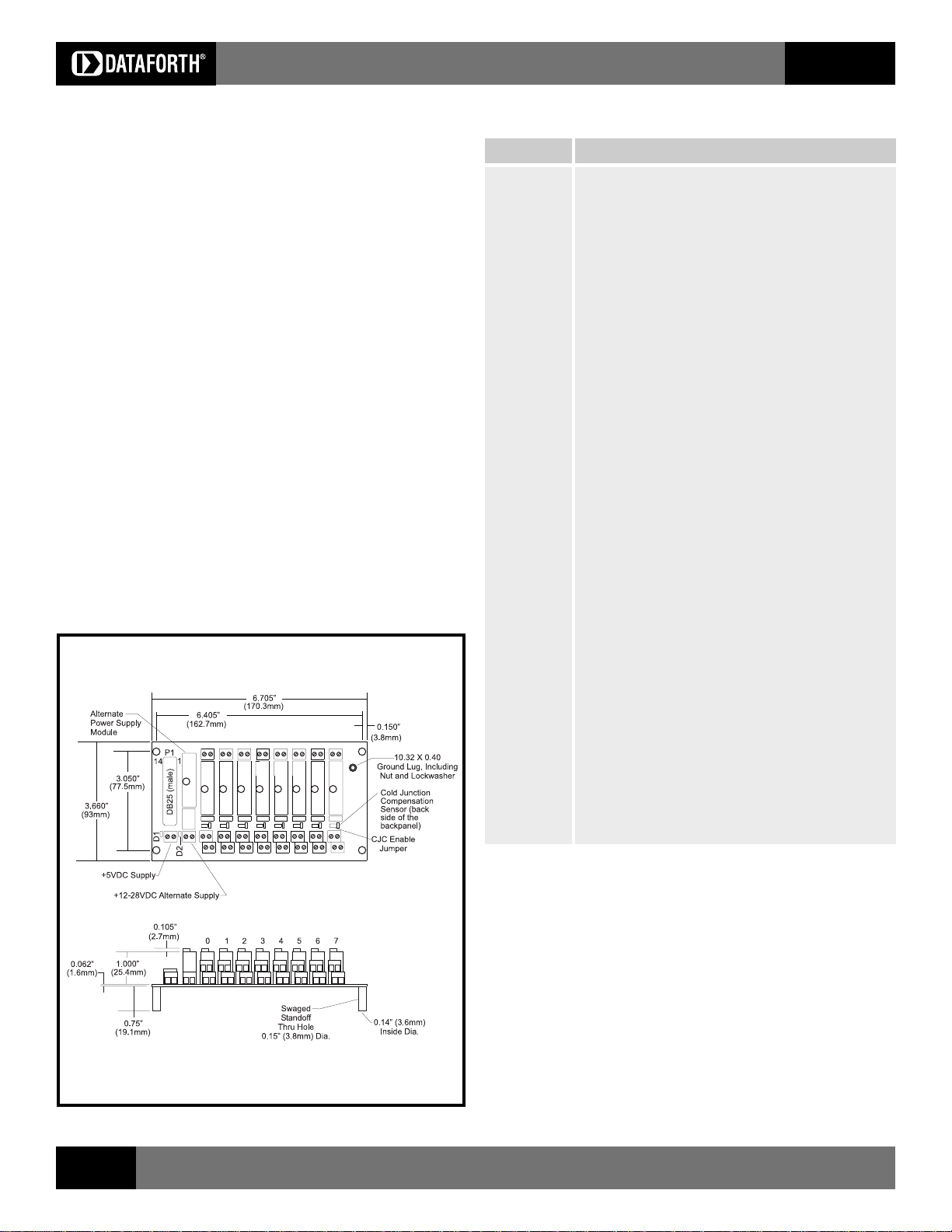
The 8BP02, 04, 08, and 16 backpanels can accept any of the 8B analog I/O
modules in any mixture and can be mounted on the SCMXRK-002 19-inch metal
rack. Analog I/O signal channels provide each module with its own analog bus.
All module outputs are simultaneously accessible to high-speed data acquisition
(ADC) boards. A temperature sensor is mounted on each channel to provide
cold junction compensation for thermocouple input modules (See Figure 5 for
schematic). Field connections are terminated with four screw terminals at each
module site. Use system interface cable SCMXCA006-XX for connection to the
host system.
8B
Cable-to-Screw-Terminal Interface Board
Power Supplies
Specifications
Operating Temperature 40°C to +85°C
Relative Humidity 95% non-condensing
Interface Connector:
Field high density screw clamp, 16 AWG max
System high density screw clamp, 16 AWG max
Figure 1: 8BP02 Analog I/O Backpanel
Figure 2: 8BP04 Analog I/O Backpanel
Visit our website www.dataforth.com
33
Page 2
SensorLex 8B Isolated Analog Signal Conditioning Products
8B
Electrical
Power
The 8B backpanels have two power supply options. A +5VDC ±5% supply can
be connected to the +5V Supply terminal block, or alternatively, a wide ranging
12-28VDC supply can be connected to the Alternate Supply terminal block. In
the latter case, the 8BPWR-2 module must be installed on the backpanel. The
backpanel contains circuitry which automatically switches between the supplies
such that only one at a time provides power to the modules. When power
connections are made to both terminal blocks simultaneously, the 12-28VDC
supply takes precedence over the +5VDC supply.
Fusing
Backpanel power is fuse protected through F1 and F2. Zener diodes D3 and
D4 provide extra protection from overvoltage and supply reversal.
Grounding
For full protection against large electrical disturbances on the field-side of the 8B
modules, a #10-32 ground stud is provided on the backpanel. An electrical
connection between this ground stud and system ground should be provided
with a large gauge wire of the shortest possible length.
Ordering Information
Part Number Description
8BP02 Standard 2-channel backpanel with standoffs for mounting.
8BP02-1 8BP02 without cold junction compensation sensor. Use when
cost savings is desired and thermocouple input modules
8B37 and 8B47 will not be used.
8BP02-2 8BP02 with DIN rail mounting option. The backpanel is
captured by DIN rail mounting elements and is shipped
fully assembled.
8BP02-3 8BP02-1 with DIN rail mounting option.
8BP04 Standard 4-channel backpanel with standoffs for mounting.
8BP04-1 8BP04 without cold junction compensation sensor. Use when
cost savings is desired and thermocouple input modules
8B37 and 8B47 will not be used.
8BP04-2 8BP04 with DIN rail mounting option. The backpanel is
captured by DIN rail mounting elements and is shipped
fully assembled.
8BP04-3 8BP04-1 with DIN rail mounting option.
8BP08 Standard 8-channel backpanel with standoffs for mounting.
8BP08-1 8BP08 without cold junction compensation sensor. Use when
cost savings is desired and thermocouple input modules
8B37 and 8B47 will not be used.
8BP08-2 8BP08 with DIN rail mounting option. The backpanel is
captured by DIN rail mounting elements and is shipped
fully assembled.
8BP08-3 8BP08-1 with DIN rail mounting option.
Figure 3: 8BP08 Analog I/O Backpanel
8BP16 Standard 16-channel backpanel with standoffs for mounting.
8BP16-1 8BP16 without cold junction compensation sensor. Use when
cost savings is desired and thermocouple input modules
8B37 and 8B47 will not be used.
8BP16-2 8BP16 with DIN rail mounting option. The backpanel is
captured by DIN rail mounting elements and is shipped
fully assembled.
8BP16-3 8BP16-1 with DIN rail mounting option.
34
For information call 800-444-7644
Page 3
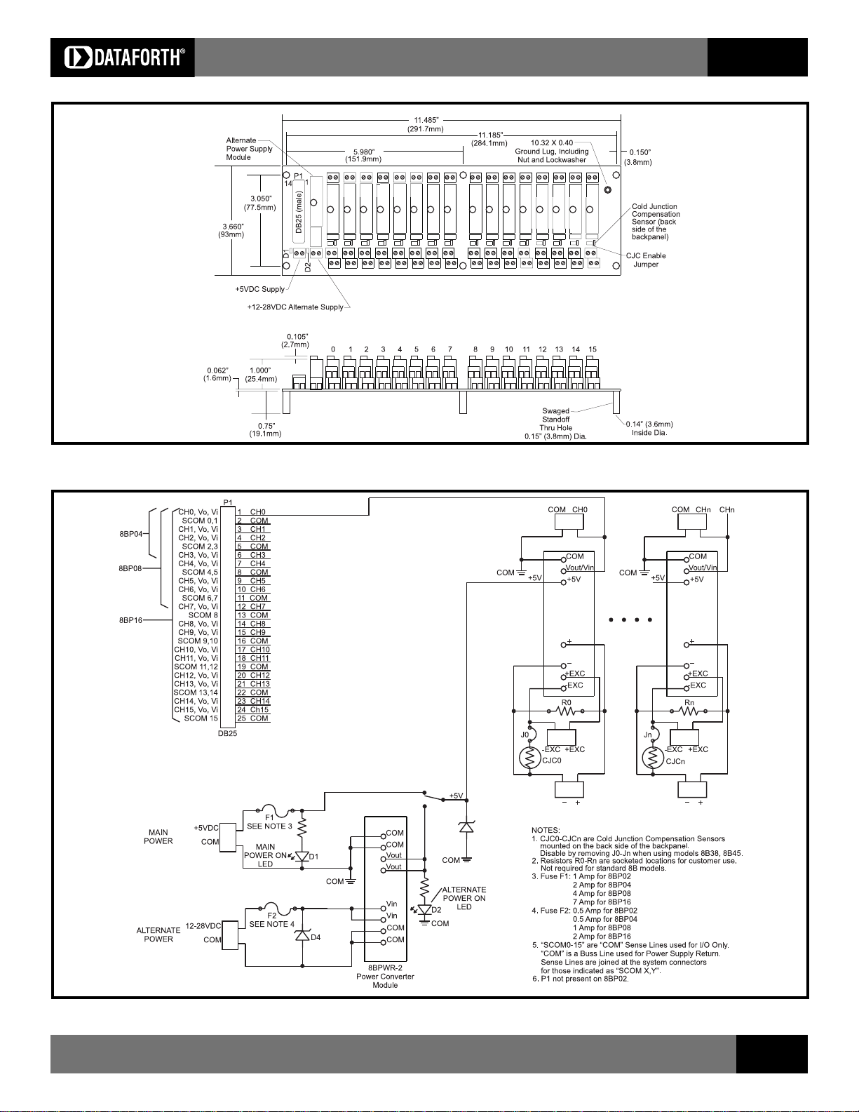
Figure 4: 8BP16 Analog I/O Backpanel
SensorLex 8B Isolated Analog Signal Conditioning Products
8B
Figure 5: 8BP02/8BP04/8BP08/8BP16 Schematic
Visit our website www.dataforth.com
35
Page 4

SensorLex 8B Isolated Analog Signal Conditioning Products
8BPWR-2
Power Supply Module
Description
The 8BPWR-2 encapsulated power supply has a wide ranging 12-28VDC
input voltage range and provides 5VDC output suitable for all 8B modules. It
is designed to mount on the 8B backpanels. The compact size and low weight
are ideal for high-density applications (see Figure 6).
8B
Specifications
Module 8BPWR-2
Input Voltage Range 12-28VDC
Overvoltage Protection None (provided on backpanel)
Reverse Voltage Protection None (provided on backpanel)
Output Voltage 5VDC ±1%
Output Voltage Temp. Coeff. ±200ppm/°C
Output Current, +85°C 2A
Output Current Limit 3A, Auto Recovery
Line Regulation ±0.20%
Load Regulation ±0.30%
Efficiency 85%
Output Ripple 50mVp-p
Mechanical Dimensions 1.11" x 1.65" x 0.40"
(h)(w)(d) (28.1mm x 41.9mm x 10.2mm)
Typical at TA=+25°C and +24V power
SCMXPRT-001, SCMXPRE-001
Power Supplies
Description
The SCMXPRT-001 and SCMXPRE-001 encapsulated power supplies are
available in 120VAC or 220VAC input voltage ranges and provide 5VDC
outputs suitable for all 8B modules. They are designed to mount on the
SCMXRK-002 metal rack (see Figure 12). The supplies are UL-recognized.
Their compact size and low weight are ideal for high-density applications (see
Figure 7).
Figure 6: 8BPWR-2 Power Supply Module
Specifications
Module SCMXPRT-001 SCMXPRE-001
Input Voltage Range, 105-125VAC 210-250VAC
47Hz to 420Hz
Output Voltage 5VDC 5VDC
Output Current, +50°C 1A 1A
Operating Temp -20°C to +71°C -20°C to +71°C
Line Regulation ±0.05% ±0.05%
Load Regulation ±0.25% ±0.25%
Output Ripple, max 1mVrms 1mVrms
Weight 1.25 lbs (567g) 1.25 lbs (567g)
Supplies are UL recognized, File No. E45344.
36
For information call 800-444-7644
Figure 7: SCMXPRT-001/E-001 Physical Dimensions
Page 5

SensorLex 8B Isolated Analog Signal Conditioning Products
SCMXPRT-003, SCMXPRE-003
Power Supplies
Description
The SCMXPRT/E-003 Linear Power Supplies are available in 120VAC or
220VAC input. They have sufficient output current capacity to supply any
combination of 8B modules. The SCMXRK-002 metal rack provides mounting
capability for the SCMXPRT/E-003 power supplies (See Figure 12).
Specifications
Module SCMXPRT-003 SCMXPRE-003
Input Voltage Range, 47Hz to 63Hz 104-132VAC 207-265VAC
Output Voltage 5VDC ±1% 5VDC ±1%
Output Current (at +70°C) 3A 3A
Output Current (at +50°C) 6A 6A
Operating Temp 0 to +70°C 0 to +70°C
Dielectric Withstand Voltage (input to ground) 3750VAC 3750VAC
Line Regulation (10% line change) ±0.05% ±0.05%
Load Regulation (50% load change) ±0.05% ±0.05%
Output Ripple (max) 5mVp-p 5mVp-p
Overvoltage Protection (factory set) 6.2V ±0.4V 6.2V ±0.4V
Both supplies are tested and certified by TUV to VDE 0806 and IEC 380. They are UL Recognized (File Number E55974)
and CSA Certified (CSA File Number LR38879).
8B
Figure 8: SCMXPRT-003/E-003 Physical Dimensions
Visit our website www.dataforth.com
37
Page 6

SensorLex 8B Isolated Analog Signal Conditioning Products
PWR-4505
25W Single Output Industrial DIN Rail Switching Power Supply
Specifications
8B
Input 85-264VAC, 120-370VDC
Frequency 47-63Hz
Input Current 1.5A/115VAC 0.75A/230VAC
Inrush Current Cold start 30A/115VAC 60A/230VAC
Efficiency 72%
Output Voltage & Current Rating 5V, 5A
Temperature Coefficient ±0.03%/°C
Ripple Voltage 100mVp-p
Overload Protection 105-150% rated output power
Over Voltage Protection 5.75-6.75V
Over Temperature Protection 135°C detect on heatsink of power transistor
Dielectric Strength Between input and output terminals: 3KV, 1 minute
Between input and FG: 1.5KV, 1 minute
Between output and FG: 0.5KV, 1 minute
Insulation Resistance Between input and output terminals/input and FG/
Output and FG: 100MΩ/500VDC
Operating Temperature -10°C to +50°C
Storage Temperature -20°C to +85°C
Relative Humidity 10-95%
Mechanical Dimensions 3.66" x 3.07" x 2.24"
(l)(w)(h) (93mm x 78mm x 57mm)
Terminal Screw M 3
▲
Features
Universal AC Input (85-264VAC)
DC Compatible Input (120-370VDC)
Protections: Short Circuit, Over Load, Over
Voltage, Over Temperature
Mounts on DIN Rail TS-35/7.5 & 15
UL, TUV Approvals
CE Compliant, UL 508 Listed
Certified to EN60950-1
Compliant with EMC Directive EN50082-2
LED Indicator for Power On
Figure 9: PWR-4505 Physical Dimensions
38
For information call 800-444-7644
Page 7

SensorLex 8B Isolated Analog Signal Conditioning Products
8B
SCMXCA006-01, -02, -07
Interface Cables
Description
SCMXCA006-XX
System interface cable for the 8BP04/08/16 backpanels. This is a DB25
Male/Female cable assembly. It can be ordered lengths of 1M, 2M, and 7M
(Figure 10).
Male DB-25
Female DB-25
8BXIF (-DIN)
Universal Interface Board
Description
The SCMXIF is a universal interface board which converts a DB25 cable input
to 25 screw terminals for discrete wire. It can be mounted on
the back of the SCMXRK-002 mounting rack (8BXIF) or on a DIN rail
(8BXIF-DIN). Required mounting hardware is included. Use
SCMXCA006-XX cable (See Figure 11 for dimensions).
Figure 10: SCMXCA006-XX System Interface Cable
SCMXRK-002
19 Inch Metal Mounting Rack
Description
The SCMXRK-002 is a 19-inch metal rack for mounting the 8BP04/08/16
backpanels and the 8BXIF interface board (See Figure 12 for dimensions).
Figure 11: 8BXIF Universal Interface Board Dimensions
Figure 12: SCMXRK-002 Analog Rack Dimensions
Visit our website www.dataforth.com
39
Page 8

SensorLex 8B Isolated Analog Signal Conditioning Products
SCMXRAIL1-XX, SCMXRAIL2-XX, SCMXRAIL3-XX
DIN Rail
Description
Three styles of DIN RAIL are available, specify length (-xx) in meters when
ordering, -01 for 1 meter or -02 for 2 meter.
8B
Figure 13: DIN Rail Styles
8BXCJC
Cold Junction Compensation Sensor
Description
Packaged for use in customer designed mounting boards. This part has an initial
tolerance of ±0.25% and comes in a standard 1206 resistor format.
Figure 14: 8BPxx-2, 8BPxx-3 Backpanel DIN Rail Mounting Option
40
For information call 800-444-7644
Page 9

WARRANTY
hereunder will, at the time of delivery, be free from defects in material and
General. Seller warrants that its products furnished
workmanship and will conform to Seller’s applicable specifications or, if
appropriate, to Buyer’s specifications accepted in writing by Seller.
SELLER’S OBLIGATION OR LIABILITY TO BUYER FOR PRODUCTS WHICH
DO NOT CONFORM TO THE ABOVE STATED WARRANTY SHALL BE
LIMITED TO SELLER, AT SELLER’S SOLE DISCRETION, EITHER
REPAIRING, REPLACING, OR REFUNDING THE PURCHASE PRICE OF THE
DEFECTIVE PRODUCT(S) PROVIDED THAT WRITTEN NOTICE OF SAID
DEFECT IS RECEIVED BY SELLER WITHIN THE TIME PERIODS SET FORTH
BELOW:
i. for all software products including licensed programs, thirty
(30) days from date of initial delivery;
ii. for all hardware products including complete systems, one
(1) year from date of initial delivery;
iii. for all special products, sixty (60) days from date of initial
delivery; and further, all products warranted hereunder for which Seller
has received timely notice of nonconformance must be returned FOB
Seller’s plant within thirty (30) days after the expiration of the warranty
periods set forth above.
The foregoing warranties shall not apply to any products which
Seller determines have, by Buyer or otherwise, been subjected to
operating and/or environmental conditions in excess of the maximum
value established therefor in the applicable specifications, or any
products that have been the subject of mishandling, misuse,
misapplication, neglect, improper testing, repair, alteration or damage.
Limitation. THE PROVISIONS OF THE FOREGOING
WARRANTIES EXTEND TO BUYER ONLY AND NOT TO BUYER’S
CUSTOMERS OR USERS OF BUYER’S PRODUCTS AND ARE IN LIEU OF
ANY OTHER WARRANTY, WHETHER EXPRESS, IMPLIED OR
STATUTORY, INCLUDING ANY IMPLIED WARRANTY OF MERCHANTABILITY OR FITNESS FOR A PARTICULAR PURPOSE. IN NO EVENT
SHALL SELLER BE LIABLE FOR INCIDENTAL, SPECIAL OR
CONSEQUENTIAL DAMAGES. Seller’s liability arising out of the produc-
tion, sale or supply of products or their use or disposition, whether based
upon warranty, contract, tort or otherwise, shall not exceed the actual
purchase price paid by Buyer for Seller’s products. Seller’s liability for any
claim of any kind shall in no case exceed the obligation or liability specified
in this Warranty.
Technical Assistance. Seller’s Warranty as hereinabove set
forth shall not be enlarged, diminished or affected by, and no obligation
or liability shall arise or grow out of, Seller’s rendering of technical advice,
facilities or service in connection with Buyer’s order of the goods
furnished hereunder.
products which it believes to be defective during the applicable warranty
Warranty Procedures. Buyer shall notify Seller of any
period and which are covered by the warranty set forth above. Buyer
shall not return any products for any reason without the prior authorization
of Seller and issuance of a Return Material Authorization number. After
issuance of an RMA number, such products shall be promptly returned
by Buyer (and in no event later than thirty (30) days after the warranty
expiration date), transportation and insurance prepaid, to the Seller’s
designated facility for examination and testing. Seller shall either repair or
replace any such products found to be so defective and promptly return
such products to Buyer, transportation and insurance prepaid. Should
Seller’s examination and testing not disclose any defect covered by the
foregoing warranty, Seller shall so advise Buyer and dispose of or return
the products in accordance with Buyer’s instructions and at Buyer’s sole
expense, and Buyer shall reimburse Seller for testing expenses incurred
at Seller’s then current repair rates.
Repair Warranty. Seller warrants its repair work and/or
replacement parts for a period of ninety (90) days from receipt by Buyer
of the repaired or replaced products or for the remainder of the warranty
period for the initial delivery of such order as set forth above in paragraph
a, whichever is greater.
Critical Applications. Certain applications using Seller’s
products may involve potential risks of death, personal injury, or severe
property or environmental damage (“Critical Applications”). SELLER’S
PRODUCTS ARE NOT DESIGNED, INTENDED, AUTHORIZED, OR
WARRANTED TO BE SUITABLE FOR USE IN LIFE-SUPPORT DEVICES
OR SYSTEMS, SAFETY EQUIPMENT, NUCLEAR FACILITY APPLICATIONS
OR OTHER CRITICAL APPLICATIONS WHERE MALFUNCTION OF THE
PRODUCT CAN BE EXPECTED TO RESULT IN PERSONAL INJURY, DEATH
OR SEVERE PROPERTY DAMAGE. BUYER USES OR SELLS SUCH
PRODUCTS FOR USE IN SUCH CRITICAL APPLICATIONS AT BUYER’S
OWN RISK AND AGREES TO DEFEND, INDEMNIFY AND HOLD HARMLESS
SELLER FROM ANY AND ALL DAMAGES, CLAIMS, SUITS OR EXPENSE
RESULTING FROM SUCH USE.
Static Sensitive. Seller ships all product in anit-static
packages. Seller’s Warranty as hereinabove set forth shall not cover
warranty repair, replacement, or refund on product or devices damaged
by static due to Buyer’s failure to properly ground.
▲
Application Support
Dataforth provides timely, high-quality product support. Just call 1-800-444-7644 TOLL-FREE
▲
Returns/Repair Policy
All warranty and repair requests should be directed to the Dataforth
Customer Service Department at (520) 741-1404. If a product return is
required, request a Return Material Authorization (RMA) number. You should
be ready to provide the following information:
1. Complete product model number.
2. Product serial number.
3. Name, address, and telephone number of person returning product.
4. Special repair instructions.
5. Purchase order number for out-of-warranty repairs.
The information provided herein is believed to be reliable; however,
DATAFORTH assumes no responsibility for inaccuracies or omissions.
DATAFORTH assumes no responsibility for the use of this information, and
all use of such information shall be entirely at the user's own risk. Application
information is intended as suggestions for possible use of the products and
The product should be carefully packaged, making sure the RMA number
appears on the outside of the package, and ship prepaid to:
Dataforth Corporation
3331 E. Hemisphere Loop
Tucson, AZ 85706 USA
not as explicit performance in a specific application. Prices and specifications are subject to change without notice. No patent rights or licenses to
any of the circuits described herein are implied or granted to any third party.
DATAFORTH does not authorize or warrant any DATAFORTH product for
use in life support devices and/or systems.
Page 10

Call 800-444-7644 for more information
or visit our website at www.dataforth.com
Dataforth Corporation
3331 E. Hemisphere Loop, Tucson, AZ 85706
techinfo@dataforth.com
Fax: 520-741-0762 T el: 520-741-1404
CAT-109E 3/06
©2004-2006 Dataforth Corporation, All Rights Reserved
ISO 9001:2000 - Registered QMS
 Loading...