

Page 1
▲
Accessories for SCM5B Analog Modules
▲
Features
1-, 2-, 8-, 16-Position Backpanels
19-Inch Mounting Rack For Backpanels
Multiplexed and Non-Multiplexed Backpanels
Interface Cables
SCMPB01
16-Position Analog I/O Backpanel,
Non-Multiplexed
Description
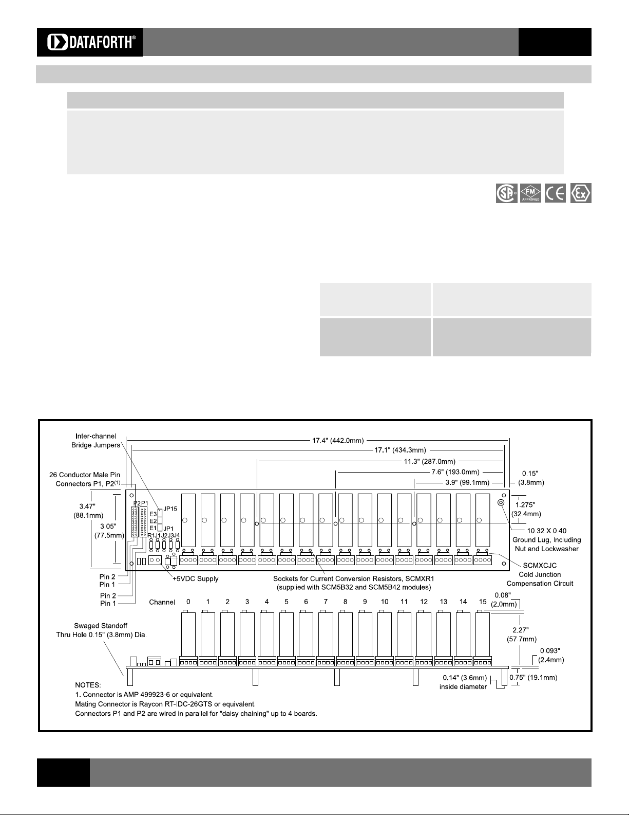
The SCMPB01 16-channel backpanel (Figure 1) can accept any of the SCM5B
analog modules in any mixture. It can be mounted on the SCMXRK-002 19-
inch metal rack. The SCMPB01 has 16 non-addressable analog I/O signal
channels which provides each module with its own analog bus. The module
output switch is continuously on when using this backpanel and all sixteen
module outputs are simultaneously accessible to high-speed data acquisition
(ADC) boards. A set of inter-channel bridge jumpers permits connecting an input
modules output to an output modules input, providing two levels of isolation. A
temperature sensor is mounted on each channel to provide cold junction
compensation for thermocouple input modules (See Figure 2 for schematic).
Field connections are terminated with four screw terminals at each module site.
Use system interface cable SCMXCA004-XX for connection to the host system.
Isolated Analog Signal Conditioning Products
Module Evaluation Board
Cable-to-Screw-Terminal Interface Board
Power Supplies
Specifications
Operating Temperature 40°C to +85°C
ATEX Group II, Category 3 20°C to +40°C
Relative Humidity 95% non-condensing
Interface Connector:
Field high density screw clamp, 14 AWG max
System 26-pin, male header connector
SCM5B
Figure 1: SCMPB01 Analog I/O Backpanel
46
For information call 800-444-7644
Page 2
Isolated Analog Signal Conditioning Products
SCM5B
SCM5B
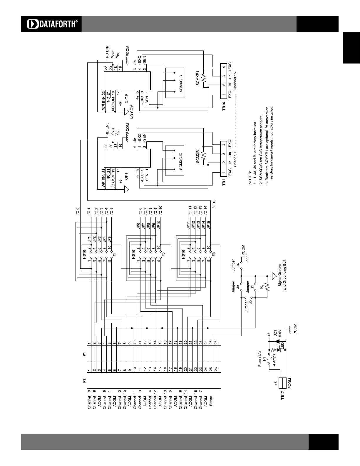
Figure 2: SCMPB01 Schematic
Visit our website www.dataforth.com
47
Page 3

Isolated Analog Signal Conditioning Products
SCM5B
Electrical
P1 and P2 Connector
Connection to the host system is made at connectors P1 and P2. These
connectors are electrically equivalent. Two connectors are provided to allow
both analog input and analog output from host systems having individual
input and output connectors.
Adjacent Channel Jumpers
Adjacent channels may be connected together to provide an isolated output
signal from an isolated input module, providing two levels of 1500V isolation.
This capability is provided with the 15 jumpers labeled JP1 through JP15 on
headers E1, E2, and E3. A simplified drawing of the SCMPB01 schematic for
Channel 1 through 4 is shown in Figure 3.
Example: Assume an SCM5B30 input module is installed in Channel 1 position
and an SCM5B39 output module is installed in Channel 2 position. If JP1 is
installed, the output of Channel 0 is connected to the input of Channel 1, which
provides two levels of 1500V isolation.
Ordering Information
Part Number Description
SCMPB01 Standard 16-channel backpanel.
SCMPB01-1 SCMPB01 without cold junction compensation circuits. Use
when cost savings is desired and thermocouple input modules
SCM5B37 and SCM5B47 will not be used.
SCMPB01-2 SCMPB01 with DIN rail mounting option. The backpanel
is mounted on a piece of anodized aluminum, which is captured
by the SCMXBEFE DIN rail mounting elements. The backpanel
is shipped fully assembled.
SCMPB01-3 SCMPB01-1 with DIN rail mounting option. See SCMPB01
and SCMPB01-2 for details.
If the host system has the capability, this allows measuring the SCMPB01
ground potential.
For proper operation of the output switch or track-and-hold circuit when using
the SCMPB01/05 backpanels, a current path must exist between the host control
logic power common and module I/O Common (module pin 19). This path
can be established on the SCMPB01 via jumper J4. If this connection exists
elsewhere in the system, jumper J4 should be removed since possible ground
loops could exist. Other connections of power ground and signal ground
usually occur at the A/D or D/A converter of the host measurement system.
More information on grounding can be found in Application Note AN502.
Figure 3: SCMPB01 Adjacent Channel Jumpers
Power
The SCMPB01 backpanel requires external +5VDC ±5% power. The chassis
mounted SCMXPRE-003 or SCMXPRT-003 power supplies have adequate
capacity to power any combination of modules.
Fusing
The SCMPB01 backpanel power is fuse protected through F1. This is a
Littlefuse type 252007, 7 amp fuse. Zener diode DZ1 provides extra protection
by clamping the input power voltage to +5.6V. If the input supply voltage
connection is reversed, this zener diode will be forward biased and fuse F1
will be blown.
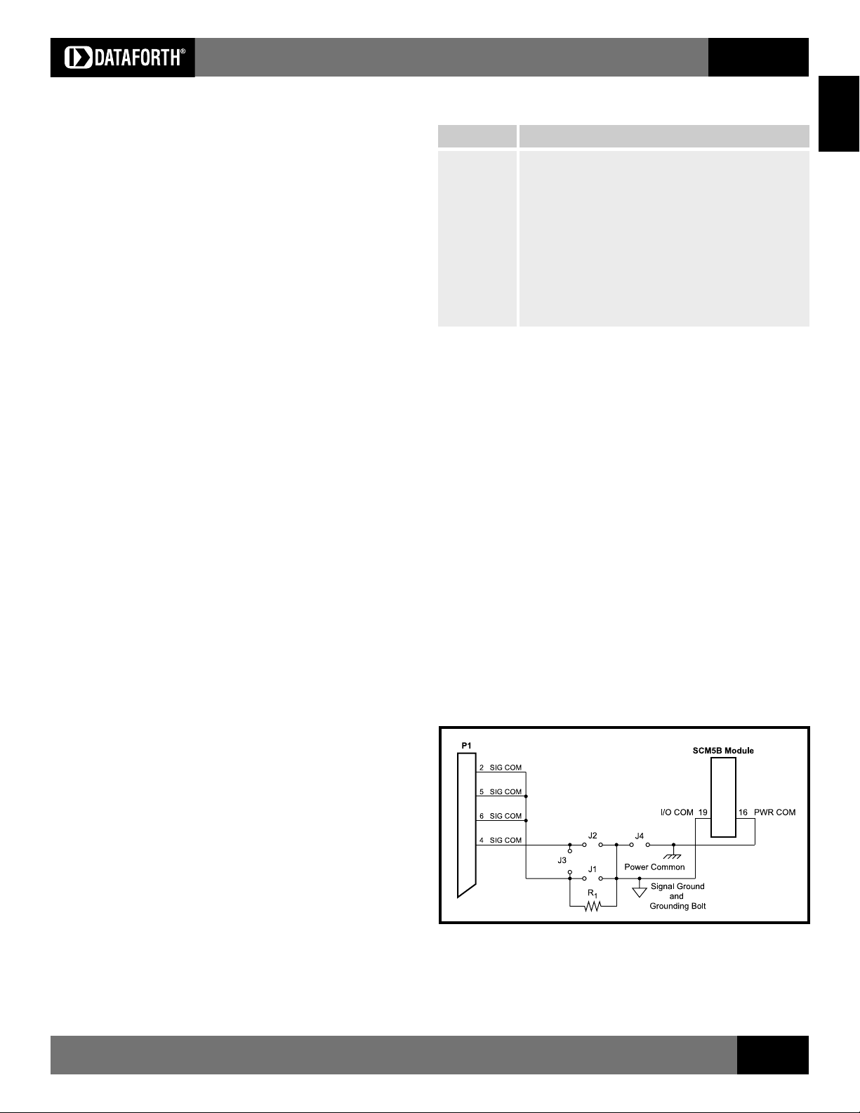
Grounding
Figure 4 details the optional ground jumper configuration available on the
SCMPB01 backpanel. Jumpers J1, J3, and J4 are factory installed.
Jumper J1 connects the AGND shield wires (pins 3, 6, 9, 12, 15, 18, 21, and
24) to the backpanel signal ground. This provides a ground connection between
the host system and backpanel. Jumper J1 is required if output modules
(SCM5B39, SCM5B49) are used, or if there is no high impedance sense input
(input low of a differential or pseudo-differential system) on the host measurement
system.
Jumper J3 connects the SENSE line (pin 25) to the backpanel signal ground.
Figure 4: SCMPB01 Grounding Diagram
If the connection of power common and AGND shield wires exist in the host
measurement system, an optional resistive connection between AGND and
the backpanel signal ground can be made via R
ohms; 100 ohms is a recommended value. Jumper J2 can be used to connect
the SENSE line to R
when this ground configuration is used.
1
. R1 can be as large as 10K
1
For full protection against large electrical disturbances on the field-side of the
SCM5B modules, a #10-32 ground stud is provided on the backpanel. An
electrical connection between this ground stud and system ground should be
provided with a large gauge wire of the shortest possible length. When this
connection is made, a possible ground loop could result through the AGND
shield wires and backpanel signal ground. If the application involves only input
modules and a differential input is used by the host measurement system, J1
should be removed. Remember that J1 is required if output modules are used
or if the host system does not have differential inputs.
48
For information call 800-444-7644
Page 4
Isolated Analog Signal Conditioning Products
SCMPB02
16-Position Analog I/O Backpanel, Multiplexed
SCM5B
SCM5B
Description
The SCMPB02 16-channel backpanel (Figure 5) can accept any of the SCM5B
analog modules in any mixture. It can be mounted on the SCMXRK-002 19-
inch metal rack. The SCMPB02 has two analog buses; one for analog input
and one for analog output. This two-bus configuration takes advantage of the
switch controlled outputs on the input modules and the track-and-hold inputs on
the output modules. A temperature sensor is mounted on each channel to
provide cold junction compensation for thermocouple input modules (See
Figure 6 for schematic). Field connections are terminated with four screw
terminals at each module site. Up to four SCMPB02 backpanels may be daisy-
chained. Use SCMXCA004-XX cable for daisy chaining and connecting to host
computer.
Specifications
Operating Temperature 40°C to +85°C
ATEX Group II, Category 3 20°C to +40°C
Relative Humidity 95% non-condensing
Interface Connector:
Field high density screw clamp, 14 AWG max
System 26-pin, male header connector
Address Input Logic Levels:
Max Logic 0 0.8V
Min Logic 1 2.0V
II Input Current, 0 or 1 0.1µA max at 25°C
1.0µA max 25°C to +85°C
RD EN\ or WR EN\ Signal
Delay from Connector P1 to
Channels 1-16
Standalone (address 0-15) 51ns at 25°C
64ns at 25°C to +85°C
Expanded (address 16-63) 100ns at 25°C
126ns at 25°C to +85°C
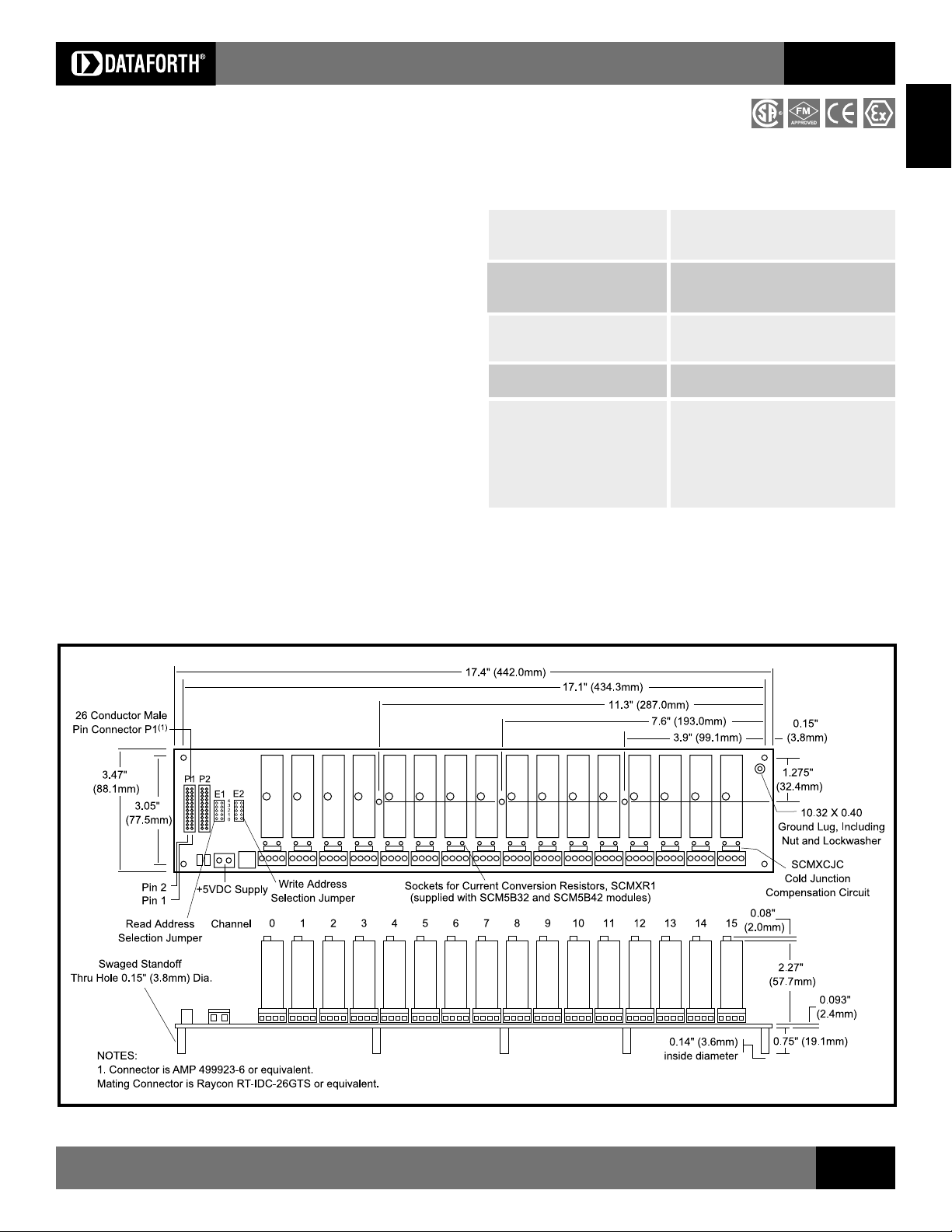
Figure 5: SCMPB02 Analog I/O Backpanel
Visit our website www.dataforth.com
49
Page 5
Isolated Analog Signal Conditioning Products
SCM5B
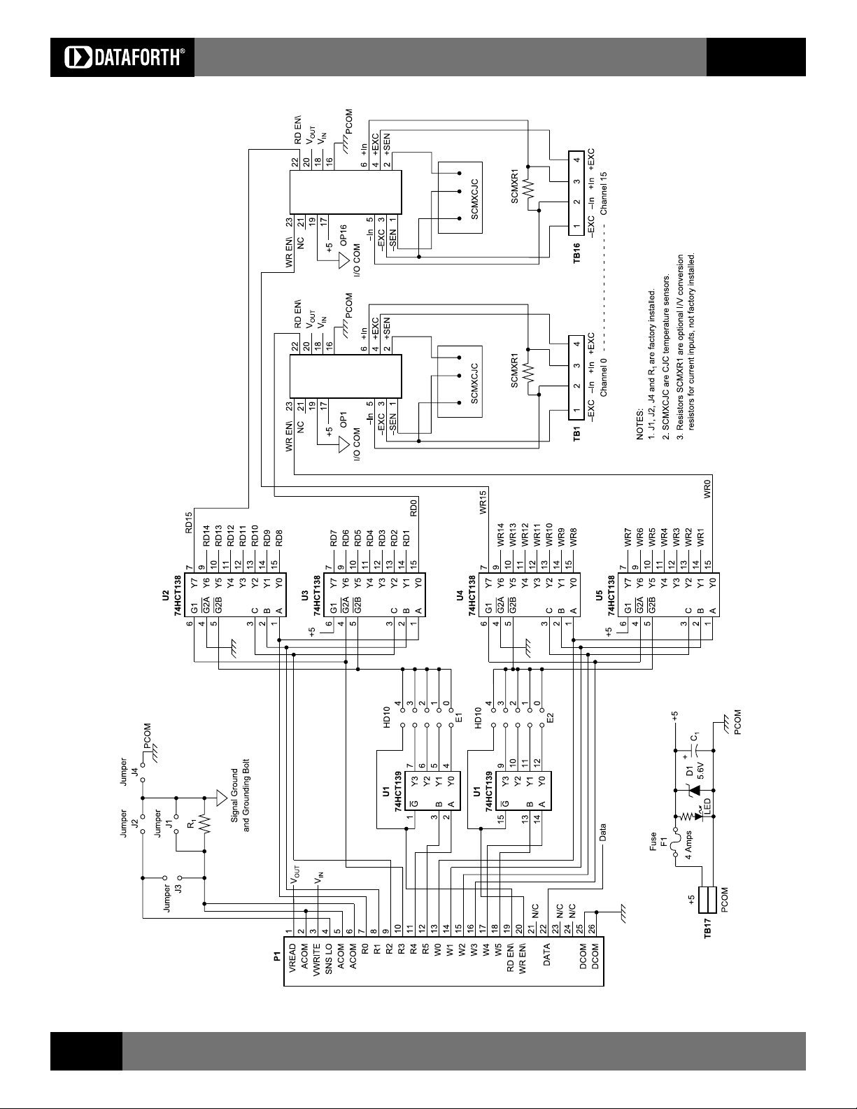
Figure 6: SCMPB02 Schematic
50
For information call 800-444-7644
Page 6
Isolated Analog Signal Conditioning Products
SCM5B
Electrical
P1 Connector
The 26 pin P1 connector provides the signal interface between the SCMPB02
backpanel and the host measurement system. Two separate analog bus
connections are provided; one for analog input signals and one for analog output
signals. Two sets of six address lines and an enable pin allow input and output
modules to be independently multiplexed onto their respective analog signal
bus. R0 thru R5 and RD EN\ are used for input modules, and W0 thru W5 and
WR EN\ are used for output modules.
Address Selection
The SCMPB02 backpanel has address decoding circuitry to allow multiplexing
any combination of up to 16 input or output modules. Capability is also provided
in the address decode circuitry to expand the system to 64 channels (four
SCMPB02 backpanels) of multiplexed input or output. Jumpers on HD10
header, E1 and E2 group, select which set of 16 addresses are assigned to a
particular backpanel. The E1 group assigns a set of 16 addresses for input
modules, and the E2 group assigns a set of 16 addresses for output modules.
The table below shows the correlation of jumper position to address range.
E1 Jumper Pos E2 Jumper Pos Address Range/Mode
4 4 0-15, STAND ALONE
3 3 48-63, EXPANDED
2 2 32-47, EXPANDED
1 1 16-31, EXPANDED
0 0 0-15, EXPANDED
To connect multiple SCMPB02 backpanels in this expanded configuration, use
interconnect cable SCMXCA004-XX.
Power
The SCMPB02 backpanel requires external +5VDC ±5% power. The chassis
mounted SCMXPRE-003 or SCMXPRT-003 power supplies have adequate
capacity to power any combination of modules.
Fusing
The SCMPB02 backpanel power is fuse protected through F1. This is a Littlefuse
type 252007, 7 amp fuse. Zener diode DZ1 provides extra protection by
clamping the input power voltage to +5.6V. If the input supply voltage connection
is reversed, this zener diode will be forward biased and fuse F1 will be blown.
Ordering Information
Part Number Description
SCMPB02 Standard 16-channel backpanel.
SCMPB02-1 SCMPB02 without cold junction compensation circuits. Use
SCMPB02-2 SCMPB02 with DIN rail mounting option. The backpanel
SCMPB02-3 SCMPB02-1 with DIN rail mounting option. See SCMPB02
For proper operation of the output switch or track-and-hold circuit when using
the SCMPB02/06 backpanels, a current path must exist between the host
control logic power common and module I/O Common (module pin 19). This
path can be established on the SCMPB02 via jumper J4. If this connection exists
elsewhere in the system, jumper J4 should be removed since possible ground
loops could exist. Other connections of power ground and signal ground usually
occur at the A/D or D/A converter of the host measurement system. More
information on grounding can be found in Application Note AN502.
If the connection of power common and SIG COM shield wires exist in the host
measurement system, a resistive connection between SIG COM and the
backpanel signal ground can be made via R
100 ohms is a recommended value. Jumper J3 can be used to connect the SNS
LO line to R
For full protection against large electrical disturbances on the field-side of the
SCM5B modules, a #10-32 ground stud is provided on the backpanel. An
electrical connection between this ground stud and system ground should be
provided with a large gauge wire of the shortest possible length. When this
connection is made, a possible ground loop could result through the SIG COM
shield wires and backpanel signal ground. If the application involves only input
modules and a differential input is used by the host measurement system, J1
should be removed. Remember that J1 is required if output modules are used
or if the host system does not have differential inputs.
when cost savings is desired and thermocouple input modules
SCM5B37 snd SCM5B47 will not be used.
is mounted on a piece of anodized aluminum, which is captured
by the SCMXBEFE DIN rail mounting elements. The backpanel
is shipped fully assembled.
and SCMPB02-2 for details.
. R1 can be as large as 10K ohms;
1
when this ground configuration is used.
1
SCM5B
Grounding
Figure 7 below details the optional ground jumper configuration available on
the SCMPB02 backpanel. Jumpers J1, J2, and J4 are factory installed.
Jumper J1 connects the SIG COM shield wires (pins 2, 5, and 6) to the backpanel
signal ground. This provides a ground connection between the host system and
backpanel. Jumper J1 is required if output modules (SCM5B39, SCM5B49) are
used, or if there is no high impedance sense input (input low of a differential or
pseudo-differential system) on the host measurement system.
Jumper J2 connects the SNS LO line (pin 4) to the backpanel signal ground.
If the host system has the capability, this allows measuring the SCMPB02
ground potential.
Visit our website www.dataforth.com
Figure 7: SCMPB02 Grounding Diagram
51
Page 7

SCMPB03/SCMPB04
One/Two Position Analog I/O Backpanels
Isolated Analog Signal Conditioning Products
SCM5B
Description
The SCMPB03 is a single channel mounting panel for the SCM5B modules.
The SCMPB04 is a dual channel mounting panel for the SCM5B modules.
They are both DIN rail compatible.
See Figures 9, and 10 for wiring diagrams, Figure 11 for schematics.
The following accessories are required for mounting one SCMPB03/04 panel
(Figure 8):
Qty Model Description
1 SCMXBEFE Base element with snap foot
2 SCMXSE Side element
The following accessories are required for mounting two or more
SCMPB03/04 panels:
Qty Model Description
2 SCMXBEFE Base element with snap foot
2 SCMXSE Side element
(# panels)-2 SCMXBE Base element without snap foot
(4 x (# panels))-4 SCMXVS Connection pins
The following DIN rail styles are available. Specify length in meters (-XX)
SCMXRAIL1-XX EN 50022-35x7.5 (slotted steel)
SCMXRAIL2-XX EN 50035-G32 (slotted steel)
SCMXRAIL3-XX EN 50022-35x15 (slotted steel)
Ordering Information
Part Number Description
SCMPB03 Standard single channel backpanel. No mounting hardware
included.
SCMPB03-2 One SCMPB03 with DIN rail mounting hardware. Shipped fully
assembled. Accepts one SCM5Bxx-xx module.
SCMPB04 Standard dual channel backpanel. No mounting hardware
included.
SCMPB04-1 SCMPB04 without cold junction compensation circuits. Use
when cost savings is desired and thermocouple input modules
SCM5B37 and SCMPB47 will not be used.
SCMPB04-2 One SCMPB04 with DIN rail mounting hardware. Shipped fully
assembled. Accepts 2 SCM5Bxx-xx modules.
SCMPB04-3 SCMPB04-1 with DIN rail mounting option. See SCMPB04
and SCMPB04-2 for details.
Specifications
Operating Temperature 40°C to +85°C
ATEX Group II, Category 3 20°C to +40°C
Relative Humidity 95% non-condensing
Interface Connector:
Field high density screw clamp, 14 AWG max
System high density screw clamp, 14 AWG max
Figure 8: DIN Rail Mounting Elements
Figure 9: SCMPB03 Analog I/O Backpanel
Figure 10: SCMPB04 Analog I/O Backpanel
52
For information call 800-444-7644
Page 8

Isolated Analog Signal Conditioning Products
NOTES:
1. Jumpers Jn are on SCMPB07
2. Jumper Jm is factory installed.
3. SCMXCJC are CJC temperature
4. Resistors SCMXR1 are optional
SCM5B
only. Factory installed.
sensors.
I/V conversion resistors for
current inputs, not factory
installed.
SCM5B
Figure 11: SCMPB03/SCMPB04/SCMPB07 Schematic
Visit our website www.dataforth.com
53
Page 9

Isolated Analog Signal Conditioning Products
SCMPB05
8-Position Analog I/O Backpanel, Non-Multiplexed
SCM5B
Description
The SCMPB05 backpanel (Figure 12) can accept up to eight SCM5B analog
input and/or output modules in any combination. It can be mounted on the
SCMXRK-002 19-inch metal rack. A separate analog signal path is provided
for each channel and each channels signal is accessible at redundant
26-pin connectors. The module output switch is continuously on when using
this backpanel and all eight module outputs are simultaneously accessible to
high-speed data acquistion (ADC) boards.
On-board jumpers permit paralleling two SCMPB05 boards to form a SCMPB01
equivalent. An additional set of inter-channel bridge jumpers permits connecting
an input modules output to an output modules input, providing two levels of
isolation (Figures 12, 13).
Jumpers on the SCMPB05 permit user selection of low (i.e. channels 0-7) or
high (i.e. channels 8-15) addresses.
A temperature sensor is mounted on each channel to provide cold junction
compensation for thermocouple input modules (See Figure 13 for
Schematic ). Field connections are terminated with four screw terminals at each
module site. Use system interface cable SCMXCA004-XX for connection to the
host system.
Specifications
Operating Temperature 40°C to +85°C
ATEX Group II, Category 3 20°C to +40°C
Relative Humidity 95% non-condensing
Interface Connector:
Field high density screw clamp, 14 AWG max
System 26-pin, male header connector
Ordering Information
Part Number Description
SCMPB05 Standard 8-channel backpanel.
SCMPB05-1 SCMPB05 without cold junction compensation circuits. Use
when cost savings is desired and thermocouple input
modules SCM5B37 and SCM5B47 will not be used.
SCMPB05-2 SCMPB05 with DIN rail mounting option. The backpanel is
mounted on a piece of anodized aluminum, which is
captured by the SCMXBEFE DIN rail mounting elements.
The backpanel is shipped fully assembled.
SCMPB05-3 SCMPB05-1 with DIN rail mounting option. See SCMPB05
and SCMPB05-2 for details.
Electrical
Address Selection
Module addresses may be selected as low (channels 0-7) or high (channels
8-15) using the sets of 3 pins labeled J5 through J12. Place a jumper over the
two pins closest to the ribbon cable connectors, P1 and P2, to select a low
address (factory configuration) or over the two pins furthest from the ribbon cable
connectors, P1 and P2, to select a high address.
Adjacent Channel Jumper
Adjacent channels may be connected together to provide an isolated output
signal from an isolated input module, providing two levels of 1500V isolation. This
capability is provided with the seven jumpers labeled JP1JP7. See page 48
for an example.
Refer to page 48 for additional notes on the P1 and P2 connectors, power
requirements, fusing and grounding issues.
Figure 12: SCMPB05 Analog I/O Backpanel
54
For information call 800-444-7644
Page 10

Isolated Analog Signal Conditioning Products
SCM5B
SCM5B
Figure 13: SCMPB05 Schematic
Visit our website www.dataforth.com
55
Page 11

SCMPB06
8-Position Analog I/O Backpanel, Multiplexed
Isolated Analog Signal Conditioning Products
SCM5B
Description
The SCMPB06 backpanel (Figure 14) can accept up to eight SCM5B modules
in any combination. It can be mounted on the SCMXRK-002 19-inch metal rack.
The SCMPB06 has two analog buses; one for analog input and one for analog
output. This two-bus configuration takes advantage of the switch controlled
outputs on the input modules and the track-and-hold inputs on the output
modules. A temperature sensor is mounted on each channel to provide cold
junction compensation for thermocouple input modules (See Figure 15 for
schematic). Field connections are terminated with four screw terminals at each
module site. Up to eight SCMPB06 backpanels may be daisy-chained. Use
SCMXCA004-XX cable for daisy chaining and connecting to host computer.
Jumpers on the SCMPB06 permit user selection of low (i.e. channels 0-7) or
high (i.e. channels 8-15) addresses.
Electrical
Address Selection
Module read and write addresses may be selected as low (channels 0-7) or
high (channels 8-15) using the four sets of 3 position jumpers labeled J5 through
J8. Place a jumper over the two pins furthest from the field I/O termination blocks
on all four sets to select a low address (factory configuration) or over the two
pins closest to the field I/O termination blocks on all four sets to select a high
address.
The SCMPB06 backpanel has address decoding circuitry to allow multiplexing
any combination of up to 8 input or output modules. Capability is also provided
in the address decode circuitry to expand the system to 64 channels (eight
SCMPB06 backpanels) of multiplexed input or output. Jumpers select which set
of 16 addresses are assigned to a particular backpanel. The Read Address
group assigns a set of 16 addresses for input modules, and the Write Address
group assigns a set of 16 addresses for output modules. The table below shows
the correlation of jumper position to address range. Refer to page 51 for
additional notes on the P1 connector, power requirements, fusing, and
grounding issues.
Ordering Information
Part Number Description
SCMPB06 Standard 8-channel backpanel.
SCMPB06-1 SCMPB06 without cold junction compensation circuits. Use
when cost savings is desired and thermocouple input modules
SCM5B37 and SCM5B47 will not be used.
SCMPB06-2 SCMPB06 with DIN rail mounting option. The backpanel is
mounted on a piece of anodized aluminum, which is captured
by the SCMXBEFE DIN rail mounting elements. The
backpanel is shipped fully assembled.
SCMPB06-3 SCMPB06-1 with DIN rail mounting option. See SCMPB06
and SCMPB06-2 for details.
Specifications
Operating Temperature 40°C to +85°C
ATEX Group II, Category 3 20°C to +40°C
Relative Humidity 95% non-condensing
Interface Connector:
Field high density screw clamp, 14 AWG max
System 26-pin, male header connector
Address Input Logic Levels:
Max Logic 0 0.8V
Min Logic 1 2.0V
II Input Current, 0 or 1 0.1µA max at 25°C
1.0µA max 25°C to +85°C
RD EN\ or WR EN\ Signal Delay
from Connector P1 to Channels 0-7
Standalone (address 0-7) 51ns at 25°C, 64ns at 25°C to +85°C
Expanded (address 8-63) 100ns at 25°C, 126ns at 25°C to +85°C
Figure 14: SCMPB06 Analog I/O Backpanel
56
For information call 800-444-7644
Page 12

Address Selection Jumpers
Read Write High/Low
Address Address Channel Address
Jumper (P2) Jumper (P3) (J5,J6,J7,J8) Address Range
1 6 L 0-7 Stand Alone
1 6 H 8-15 Stand Alone
2 7 L 48-55 Expanded
2 7 H 56-63 Expanded
3 8 L 32-39 Expanded
3 8 H 40-47 Expanded
4 9 L 16-23 Expanded
4 9 H 24-31 Expanded
5 10 L 0-7 Expanded
5 10 H 8-15 Expanded
Isolated Analog Signal Conditioning Products
SCM5B
SCM5B
Figure 15: SCMPB06 Schematic
Visit our website www.dataforth.com
57
Page 13

SCMPB07
8-Position Backpanel, High Density
Isolated Analog Signal Conditioning Products
SCM5B
Description
The SCMPB07 8-channel high-density backpanel can accept any of the
SCM5B analog modules in any mixture. Its overall width is 5.5 inches (139.7mm)
versus 10 inches (254mm) for the SCMPB05 and SCMPB06 8-channel
backpanels. Separate analog signal paths are provided for each channel. Each
channel provides four high-density screw terminals for field connections and
two high-density screw terminals for host system connection. It also provides
a jumper on each channel to optionally connect or isolate each modules I/O
common from other channel's I/O common and/or power common. (Figure 16.)
See Figure 11 on page 53 for schematic.
Specifications
Operating Temperature 40°C to +85°C
ATEX Group II, Category 3 20°C to +40°C
Relative Humidity 95% non-condensing
Interface Connector:
Field high density screw clamp, 14 AWG max
System 26-pin, male header connector
Ordering Information
Part Number Description
SCMPB07 Standard 8-channel backpanel. No mounting hardware
included.
SCMPB07-1 SCMPB07 without cold junction compensation circuits. Use
when cost savings is desired and thermocouple input modules
SCM5B37 and SCMPB47 will not be used.
SCMPB07-2 SCMPB07 with DIN rail mounting hardware. Shipped fully
assembled. Accepts 8 SCM5Bxx-xx modules.
SCMPB07-3 SCMPB07-1 with DIN rail mounting option.
Figure 16: SCMPB07 Analog I/O Backpanel
58
For information call 800-444-7644
Page 14

SCMXEV
Analog Module Evaluation Board
Description
The SCMXEV is a single channel board with a test socket for SCM5B module
evaluation (Figure 17). All signal input/output, control, and power connections
are connected to terminal blocks for ease of user access. A cold junction
temperature sensor circuit is included for evaluation of thermocouple modules.
(See Figure 18 for schematic).
The SCMXEV is mechanically compatible with DIN rail mounting. Phoenix
brand Universal Module (UM) elements may be used. The following Phoenix
parts would be used to mount one SCMXEV.
2, UM-BEFE base elements with snap foot
2, UM-SE side elements
4, UM-VS connection pins
Two jumpers are provided for customer use. The first, J1, provides a current
path between +5V Power Common (module pin 16) and I/O Common (module
pin 19). A path must exist between the host control logic power common and
module I/O Common for proper operation of the module output switch or track-
and-hold circuit. If this connection exists elsewhere in the system, jumper J1
should be removed since possible ground loops could exist. Other connections
of power ground and signal ground usually occur at the A/D or D/A converter
of the host measurement system.
Isolated Analog Signal Conditioning Products
Figure 17: SCMXEV Evaluation Board Dimensions and Pin Layout
SCM5B
SCM5B
Jumper J2 is used in the cold junction compensation circuit. If it is installed, the
compensation circuit is enabled and will provide the proper compensation
voltage to correct for the thermoelectric effect at the +In and In screw terminals.
If an external simulation voltage is desired for cold junction compensation, J2
should be removed. The external voltage is applied at the sockets labled CJC+
and CJC. An external voltage of 510.0mV corresponds to an ambient
temperature of +25 °C. The transfer function of the onboard compensation circuit
is V
= 0.510 0.0025(T25)V.
CJC
Figure 18: SCMXEV Evaluation Board Schematic
Visit our website www.dataforth.com
59
Page 15

Isolated Analog Signal Conditioning Products
SCM5B
SCMXCA004-XX, SCMXCA005
Interface Cables
Description
SCMXCA004-XX
System interface cable for the SCMPB01/02/05/06 backpanels. This is a 26
conductor ribbon cable with a mass-terminated socket connector installed on
each end. It can be ordered in any length; -xx denotes required length in
meters (Figure 19).
SCMXIF (-DIN)
Universal Interface Board
Description
The SCMXIF is a universal interface board which converts a 26-pin ribbon
cable input to 26 screw terminals for discrete wire. It can be mounted on
the back of the SCMXRK-002 mounting rack (SCMXIF) or on a DIN rail
(SCMXIF-DIN). Required mounting hardware is included. Use
SCMXCA004-XX cable (See Figure 22 for dimensions).
Figure 19: SCMXCA004-XX System Interface Cable
SCMXRK-002
19 Inch Metal Mounting Rack
Description
The SCMXRK-002 is a 19-inch metal rack for mounting the SCMPB01/02/05/
06 backpanels. It also provides capability to mount the SCMXPRT-001,
SCMXPRE-001, SCMXPRT-003 or SCMXPRE-003 power supplies, and
the SCMXIF interface board (See Figure 21 for dimensions).
Figure 22: SCMXIF Universal Interface Board Dimensions
Figure 21: SCMXRK-002 Analog Rack Dimensions
60
For information call 800-444-7644
Page 16

SCMXCJC
Encapsulated Cold Junction Compensation
Description
The SCMXCJC is the identical circuit used on the SCMPB01/02/03/04/05/06/07
backpanels except it is packaged as a component for use in customer designed
mounting boards (Figure 23). When interfaced to an SCM5B37 or 47 module
the transfer function of the voltage across the +SEN and SEN pins is V
0.0025(T 25)V.
Specifications
Accuracy +25°C ±0.25°C
+5°C to +45°C ±0.5°C
40°C to +85°C ±1.25°C
= 0.510
CJC
Isolated Analog Signal Conditioning Products
SCM5B
SCM5B
SCM5BPT
Pass Thru Module
Description
The SCM5BPT is a pass-through module used to establish a direct connection
between an input signal and the SCM5B series backplane analog bus. It has
unity gain and no isolation. It accepts up to
output .
±10V input and provides up to ±10V
SCM5BPT-1367
Pass Thru Module with Switch
Description
The SCM5BPT-1367 is a pass-through module used to establish a direct
connection between an input signal and the SCM5B series backplane analog
bus. It has unity gain, no isolation, and a logic controlled output switch which
allows sharing of a common analog bus with other SCM5B modules. It accepts
up to
±10V input and provides up to ±10V output . Resettable fuses and
overvoltage protection circuitry protect computer-side electronics.
SCMXJP-003
Jumper Strap
Figure 23: SCMXCJC Physical Dimensions and Pin Layout
SCMXR1
Current Conversion Resistor
Description
A precision 20Ω, 0.1%, 10ppm/°C resistor used with the SCM5B32 current
input module or SCM5B42 two-wire transmitter interface module (Figure 24).
Sockets are provided on the SCMPB01/02/03/04/05/06/07 and
SCMXEV backpanels to allow installation of this resistor. One SCMXR1 is
shipped with each SCM5B32 or SCM5B42 module.
Description
Package of 10 jumpers for connecting adjacent input/output modules on the
SCMPB01 backpanel. This connection is made if it is desired to direct the output
of any input module to the input of an adjacent output module. The jumpers can
also be used for configuring I/O addresses on the SCMPB02 backpanel.
SCMXFS-003
Fuse
Description
Package of 10, 4 amp fuses for use on the SCMPB01 or SCMPB02 backpanel.
This is a series fuse in the five volt power line. It provides protection against
inadvertent reverse connection of five volt power.
Visit our website www.dataforth.com
Figure 24: SCMXR1 Physical Dimensions
61
Page 17

Isolated Analog Signal Conditioning Products
SCM5B-PROTO
Breadboard Kit
Description
The SCM5B-PROTO breadboard kit was designed to allow users to incorpo-
rate their own module functions using an SCM5B format. The kit includes a pc
board designed for breadboard circuits, a module case, header and mounting
screw. Contact the factory for additional information.
SCMXRAIL1-XX, SCMXRAIL2-XX, SCMXRAIL3-XX
DIN Rail
Description
Three styles of DIN RAIL are available, specify length when ordering.
SCM5B
Figure 25: DIN Rail Styles
SCMXPRT-001, SCMXPRE-001
Power Supplies
Description
The SCMXPRT-001 and SCMXPRE-001 encapsulated power supplies are
available in 120VAC or 220VAC input voltage ranges and provide 5VDC
outputs suitable for all SCM5B modules. They are designed to mount on the
Specifications
Module SCMXPRT-001 SCMXPRE-001
Input Voltage Range, 105-125VAC 200-240VAC
47Hz to 63Hz
Output Voltage 5VDC 5VDC
Output Current, +50°C 1A 1A
(derate 2.5%/°C above +50°C)
Operating Temp -25°C to +71°C -25°C to +71°C
Dielectric Withstand V 2500Vrms 2500Vrms
(Input to Ground)
Line Regulation ±0.05% ±0.05%
Load Regulation ±0.15% ±0.15%
Output Ripple, max 2mVrms 2mVrms
Overvoltage Protection 6.2V 6.2V
Weight 1.25 lbs (567g) 1.25 lbs (567g)
Supplies are UL recognized, File No. E65890.
SCMXRK-002 metal rack. The supplies are UL-recognized. Their compact
size and low weight are ideal for high-density applications (see Figure 26).
62
Figure 26: SCMXPRT-001/E-001 Physical Dimensions
For information call 800-444-7644
Page 18

Isolated Analog Signal Conditioning Products
SCMXPRT-003, SCMXPRE-003
Power Supplies
Description
The SCMXPRT/E-003 Linear Power Supplies are available in 120VAC or
220VAC input. They have sufficient output current capacity to supply any
combination of SCM5B modules. The SCMXRK-002 metal rack provides
mounting capability for the SCMXPRT/E-003 power supplies (See Figure 27).
Specifications
Module SCMXPRT-003 SCMXPRE-003
Input Voltage Range, 47Hz to 63Hz 104-132VAC 207-265VAC
Output Voltage 5VDC ±1% 5VDC ±1%
Output Current (at +70°C) 3A 3A
Output Current (at +50°C) 6A 6A
Operating Temp 0 to +70°C 0 to +70°C
Dielectric Withstand Voltage (input to ground) 3750VAC 3750VAC
Line Regulation (10% line change) ±0.05% ±0.05%
Load Regulation (50% load change) ±0.05% ±0.05%
Output Ripple (max) 5mVp-p 5mVp-p
Overvoltage Protection (factory set) 6.2V ±0.4V 6.2V ±0.4V
Both supplies are tested and certified by TUV to VDE 0806 and IEC 380. They are UL Recognized (File Number E55974)
and CSA Certified (CSA File Number LR38879).
SCM5B
SCM5B
Figure 27: SCMXPRT-003/E-003 Physical Dimensions
Visit our website www.dataforth.com
63
 Loading...