

Page 1
Isolated Process Control Signal Conditioning Products
SCM7B36
Isolated Potentiometer Input Modules
Description
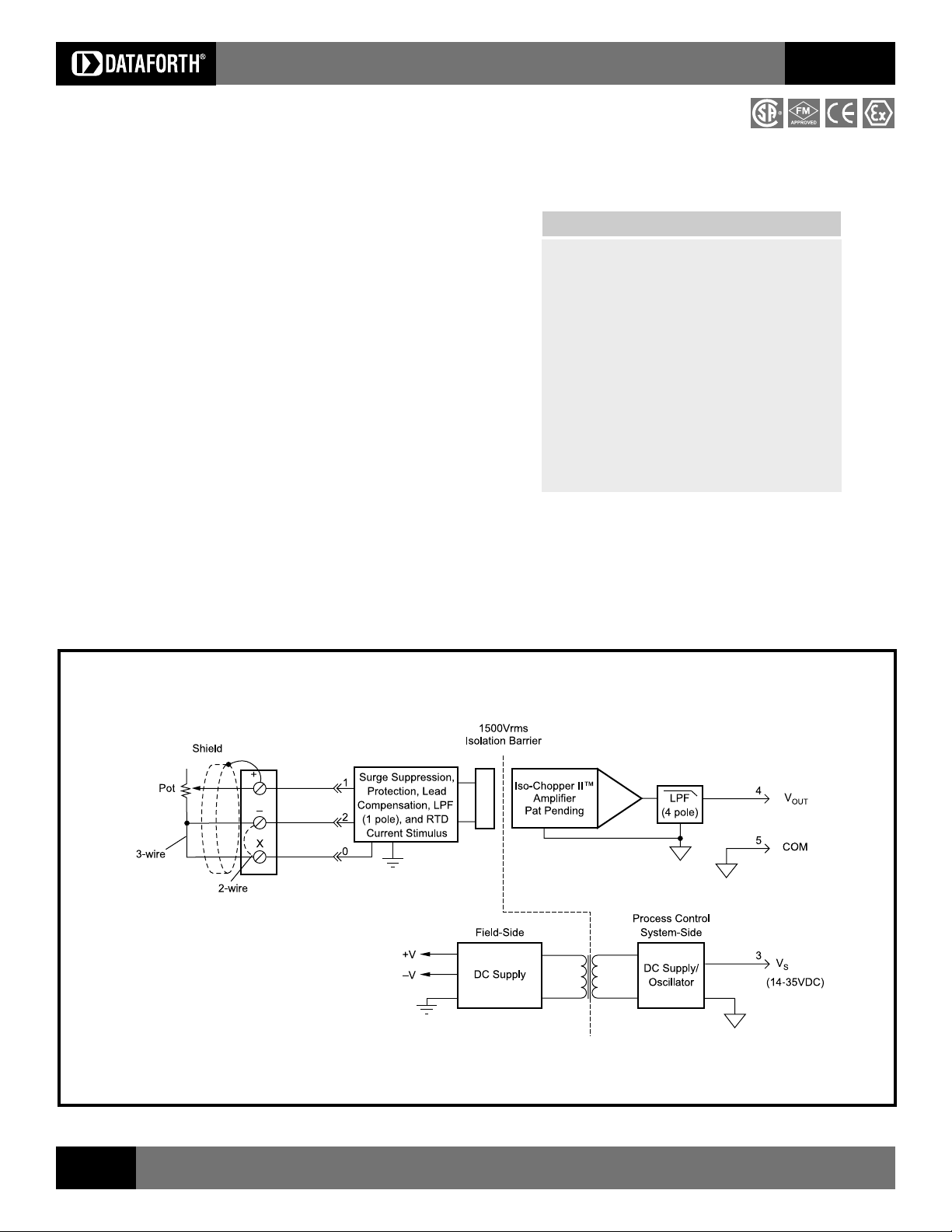
Each SCM7B36 Potentiometer input module provides a single channel of
resistance input which is filtered, isolated, amplified, and converted to a high level
analog voltage output.
The SCM7B36 module interfaces to slidewires and potentiometers in both two
or three wire configuration and incorporates a five-pole filtering approach to
maximize both time and frequency response by taking advantage of both Bessel
and Butterworth characteristics. One pole of the filter is on the field side of the
isolation barrier; four are on the process control system side. In the 3-Wire
configuration, lead resistance compensation is provided if the resistance of the
x lead is closely equivalent to that of the + lead. Internal to the module,
measurement error due to lead resistance is canceled.
In response to the low level current excitation, and after initial field-side filtering,
the input signal is chopped by a proprietary chopper circuit and transferred
across the transformer isolation barrier, suppressing transmission of common
mode spikes and surges. The signal is then reconstructed and filtered for
process control system output.
▲
Features
Industrys First 7B Potentiometer Input
Module
Interfaces 100
High Level Voltage Outputs
1500Vrms Transformer Isolation
Accuracy, ±0.03% of Span Typical,
±0.1% Max
ANSI/IEEE C37.90.1 Transient Protection
Input Protected to 120Vrms Continuous
CSA Certified, FM Approved
CE and ATEX Compliant
Ω to 10kΩ Potentiometers
SCM7B
Six standard input resistance ranges are offered, from 100
output ranges available: 0-5V, 1-5V, and 0-10V. Modules accept a wide 14-
35VDC power supply range (+24VDC nominal). Their compact packages
(2.13" x 1.705" x 0.605" max.) save space and are ideal for high channel
density applications. They are designed for easy DIN rail mounting using any
of Dataforths -DIN backpanels.
Ω to 10kΩ, with three
Figure 1: SCM7B36 Block Diagram
76
For information call 800-444-7644
Page 2

Isolated Process Control Signal Conditioning Products
SCM7B
Specifications
Module
Typical at 25°C and +24VDC
SCM7B36
Input Range (See Ordering Information)
Protection
Continuous 120Vrms max
Transient ANSI/IEEE C37.90.1
Sensor Excitation Current 65µA (10kΩ) to 260µA (100Ω)
Lead Resistance Effect (3-Wire)
(1)
-01 thru -04 : ±0.005Ω/Ω
-05 : ±0.02Ω/Ω
-06 : ±0.04Ω/Ω
Output Range
(See Output Range)
Effective Available Power
(2)
(2)
40mW
Resistance < 1Ω
Protection Continuous Short-to-Ground
Voltage/Current Limit ±12V, ±14mA
CMV (Input to Output)
Continuous 1500Vrms
Transient ANSI/IEEE C37.90.1
CMRR (50 or 60Hz) 120dB
Accuracy
Nonlinearity
(3)
(4)
±0.03% Span typical,
±0.1% Span max
±0.01% Span typical,
±0.02% Span max
Stability (-40°C to +85°C)
Input Offset ±0.01Ω/°C
Output Offset ±30µV/°C
Gain ±60ppm/°C
Noise Peak at 5MHz B/W 1mV
RMS at 10Hz to 100kHz B/W 250µV
Peak at 0.1Hz to 10Hz B/W 1µV RTI
Open Input Response
+ Lead Upscale
Lead Non-deterministic
x Lead Downscale
Open Input Detection Time <5s
Frequency and Time Response
Bandwidth, -3dB 3Hz
NMR (50/60Hz) 80/85dB
Step Response, 0 to 90% 250ms
Supply Voltage 14-35VDC
2
Current
Sensitivity ±0.0001%/%V
12mA
S
Mechanical Dimensions 2.13" x 1.705" x 0.605", max
(h)(w)(d) 54.1mm x 43.3mm x 15.4mm max
Environmental
Operating Temp. Range -40°C to +85°C
ATEX Group II, Category 3 -20°C to +40°C
Storage Temp. Range -40°C to +85°C
Relative Humidity 0 to 95% Noncondensing
Emissions EN61000-6-4 ISM, Group 1
Radiated, Conducted Class A
Immunity EN61000-6-2 ISM, Group 1
R F Performance A ±0.5% Span Error
ESD, EFT, Surge, Voltage Dips Performance B
NOTES:
(1) Lead resistance effect is given for the condition of not having the NTC thermistor installed in the
backpanel. As a general rule; as long as the lead resistance of the (+) lead matches the parallel
combination of the thermistor and lead resistance in the (X) lead, the given specifications apply.
(2) Output Range and Supply Current specifications are based on minimum output load resistance.
Minimum output load resistance is calculated by V
Power that guarantees output range and accuracy specifications.
(3) Accuracy includes the effects of repeatability, hysteresis, and linearity, but does not include sensor
accuracy.
(4) Nonlinearity is calculated using the best-fit straight line method.
2
/PE, where PE is the output Effective Available
OUT
Ordering Information
Model Input Range
SCM7B36-01 0 - 100Ω
SCM7B36-02 0 - 200Ω
SCM7B36-03 0 - 500Ω
SCM7B36-04 0 - 1kΩ
SCM7B36-05 0 - 5kΩ
SCM7B36-06 0 - 10kΩ
Output Ranges Available
Output Range Part No. Suffix Example
+1 to +5V NONE SCM7B36-01
0 to +5V A SCM7B36-01A
0 to +10V D SCM7B36-01D
SCM7B
Visit our website www.dataforth.com
77
 Loading...