

Page 1
SCM5B33
Isolated True RMS Input Modules
Description
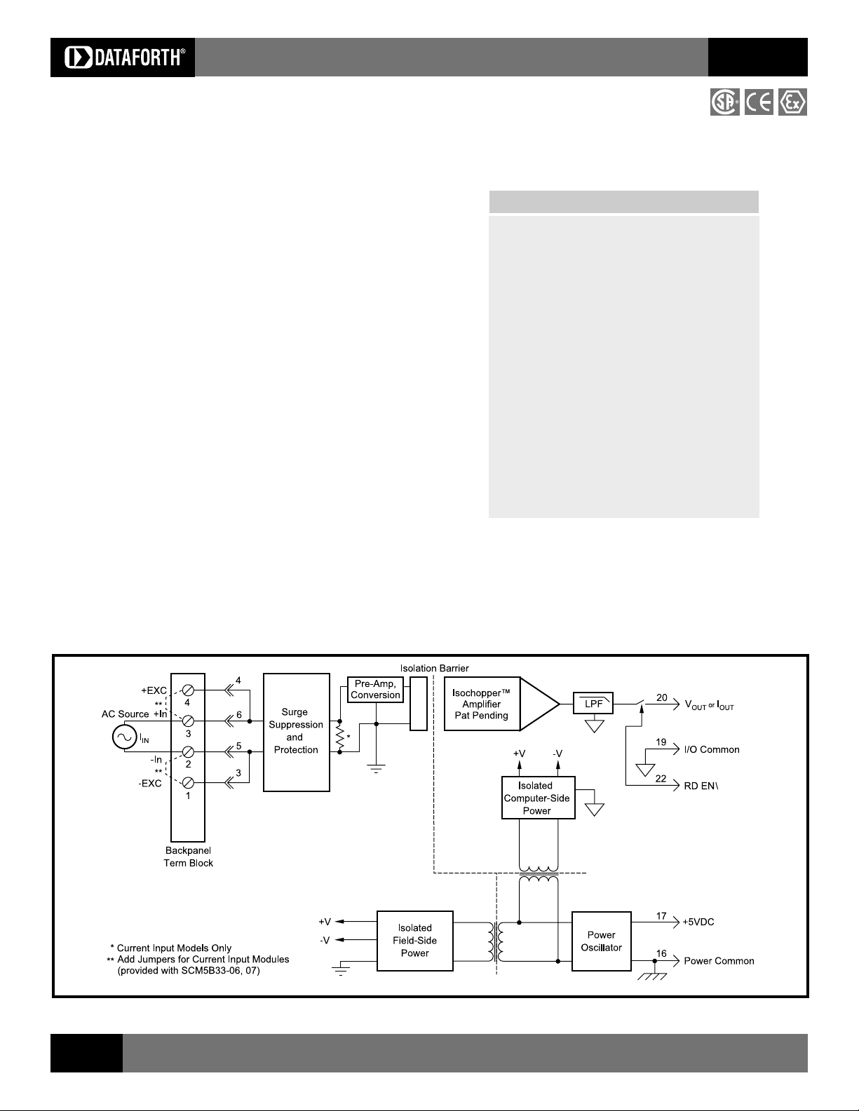
Each SCM5B33 True RMS input module provides a single channel of AC input
which is converted to its True RMS DC value, filtered, isolated, amplified, and
converted to a standard process voltage or current output (Figure 1).
The SCM5B modules are designed with a completely isolated computer side
circuit which can be floated to ±50V from Power Common, pin 16. This complete
isolation means that no connection is required between I/O Common and Power
Common for proper operation of the output switch. If desired, the output switch
can be turned on continuously by simply connecting pin 22, the Read-Enable
pin, to I/O Common, pin 19.
The field voltage or current input signal is processed through a pre-amplifier and
RMS converter on the field side of the isolation barrier. The converted DC signal
is then chopped by a proprietary chopper circuit and transferred across the
transformer isolation barrier, suppressing transmission of common mode
spikes and surges. The computer side circuitry reconstructs, filters and converts
the signal to industry standard outputs. Modules are powered from
+5VDC, ±5%.
For current output models, an external loop supply of 4.2V to 26V is required.
The loop supply connection, with series load, is between Pin 20 (+) and
Pin 19 (-).
Isolated Analog Signal Conditioning Products
▲
Features
Interfaces RMS Voltage (0 300V) or RMS
Current (0 5A)
Designed for Standard Operation with
Frequencies of 45Hz to 1000Hz
(Extended Range to 20kHz)
Compatible with Standard Current and
Potential Transformers
Industry Standard Output of either 0-1mA,
0-20mA, 4-20mA, 0-5V or 0-10VDC
±0.25% Factory Calibrated Accuracy
(Accuracy Class 0.2)
1500Vrms Continuous Transformer Isolation
Input Overload Protected to 480V Max
(Peak AC & DC) or 10A RMS Continuous
ANSI/IEEE C37.90.1 Transient Protection
CSA Certified, CE and ATEX Compliant
SCM5B
Figure 1: SCM5B33 Block Diagram
10
For information call 800-444-7644
Page 2

Isolated Analog Signal Conditioning Products
SCM5B
Specifications
Module
Input
Signal Range 100mV to 300Vrms, 0 to 5Arms
Standard Frequency Range 45Hz to 1000Hz
Extended Frequency Range 1kHz to 20kHz
Impedance 1 MΩ ±1% shunted by 100pF (-01 thru -05),
Coupling AC
Protection
Output
Signal Range 0-5V or 0-10V or 0-1mA or 0-20mA or 4-20mA
Current Limit 1.4mA (0-1mA models), 30mA (0/4-20mA models),
Voltage Limit ±18V (0-5, 0-10V models)
Resistance 50Ω (0-5, 0-10V models)
Protection Continuous Short to Ground
Ripple and Noise (100kHz) 0.025% Span rms
Accuracy
Sinusoid
Non-Sinusoid
Vs. Temperature ±100ppm/°C
Isolation (Common Mode)
Input to Output, Input to Power
Continuous 1500Vrms max
Transient ANSI/IEEE C37.90.1
Output to Power
Continuous 50VDC max
Rejection (50-60Hz Common Mode) 100dB
Response Time (0 to 99%) <400ms
Output Enable Control
Selection Time 6.0µS at C
Voltage
Max Logic 0 +0.8V
Min/Max Logic 1 +2.4V/+36V
Current 0,1 0.5µA
Loop Voltage +4.2VDC min, +26VDC max, -40°C to +85°C
Load Resistance (maximum) (Loop Voltage - 4.2) / (Loop Current)
Supply Voltage +5VDC ±5%
Current 120mA
Sensitivity ±200ppm/%
Environmental
Operating Temp. Range -40°C to +85°C
ATEX Group II, Category 3 -20°C to +40°C
Storage Temp. Range -40°C to +85°C
Relative Humidity 0 to 95% Noncondensing
Emissions EN61000-6-4 ISM, Group 1
Immunity EN61000-6-2 ISM, Group 1
Dimensions (h)(w)(d) 2.28" x 2.26" x 0.60" (58mm x 57mm x 15mm)
NOTES:
(1) SCM5B33 and SCMPB01, 02, 03, 04, 05, 06, 07, XEV rating only. Backpanels obtained from other sources may have lower ratings.
(2) For 1 to 25 seconds the max allowable transient current rating is √ 2500 / (event time). For less than 1 second,
ANSI/IEEE C-37.90.1 applies with a 0.05
(1)
Continuous (-01 thru -05) 300Vrms
Continuous (-06 thru -07) 10Arms
Transient (-01 thru -05) ANSI/IEEE C37.90.1
Transient (-06 thru -07) See note 2
(3)(4)
50/60 Hz ±0.25% Span
45Hz to 1kHz ±0.25% Reading Additional Factor
1kHz to 20kHz ±0.75% Reading Additional Factor
Crest Factor = 1 to 2 ±0.05% Reading Additional Error
Crest Factor = 2 to 3 ±0.15% Reading Additional Error
Crest Factor = 3 to 4 ±0.30% Reading Additional Error
Crest Factor = 4 to 5 ±0.40% Reading Additional Error
Radiated, Conducted Class A
R F Performance A ±0.5% Span Error
ESD, EFT, Surge, Voltage Dips Perfor mance B
Typical at TA=+25°C and +5V power
SCM5B33
0.10Ω (-06), 0.025Ω (-07)
8mA (0-5, 0-10V models)
= 0 to 2000pF
LOAD
Ω load. For greater than 25 seconds, the 10A rms continuous rating applies.
Ordering Information
Model Input (rms)Output (DC)
SCM5B33-01 0-100mV 0-5V
SCM5B33-02 0-1V 0-5V
SCM5B33-03 0-10V 0-5V
SCM5B33-04 0-150V 0-5V
SCM5B33-05 0-300V 0-5V
SCM5B33-06 0-1A 0-5V
SCM5B33-07 0-5A 0-5V
SCM5B33-01B 0-100mV 0-1mA
SCM5B33-02B 0-1V 0-1mA
SCM5B33-03B 0-10V 0-1mA
SCM5B33-04B 0-150V 0-1mA
SCM5B33-05B 0-300V 0-1mA
SCM5B33-06B 0-1A 0-1mA
SCM5B33-07B 0-5A 0-1mA
SCM5B33-01C 0-100mV 4-20mA
SCM5B33-02C 0-1V 4-20mA
SCM5B33-03C 0-10V 4-20mA
SCM5B33-04C 0-150V 4-20mA
SCM5B33-05C 0-300V 4-20mA
SCM5B33-06C 0-1A 4-20mA
SCM5B33-07C 0-5A 4-20mA
SCM5B33-01D 0-100mV 0-10V
SCM5B33-02D 0-1V 0-10V
SCM5B33-03D 0-10V 0-10V
SCM5B33-04D 0-150V 0-10V
SCM5B33-05D 0-300V 0-10V
SCM5B33-06D 0-1A 0-10V
SCM5B33-07D 0-5A 0-10V
SCM5B33-01E 0-100mV 0-20mA
SCM5B33-02E 0-1V 0-20mA
SCM5B33-03E 0-10V 0-20mA
SCM5B33-04E 0-150V 0-20mA
SCM5B33-05E 0-300V 0-20mA
SCM5B33-06E 0-1A 0-20mA
SCM5B33-07E 0-5A 0-20mA
Modules can be ordered with other input/output ranges. Consult factory
for ordering details and specifications.
Output Ranges Available
Output Range Part No. Suffix Example
3. 0V to +5V NONE SCM5B33-01
4. 0V to +10V D SCM5B33-01D
5. 4mA to 20mA C SCM5B33-01C
6. 0mA to 20mA E SCM5B33-01E
7. 0mA to 1mA B SCM5B33-01B
(3) At standard 60Hz factory calibration. Consult factory for
calibration at other frequencies.
(4) For 10-100% rated span. Add 0.25% accuracy error (-02 thru -07) or
1.00% accuracy error (-01) for 0-10% Span measurements. Accuracy
includes nonlinearity, hysteresis and repeatability but not source or
external shunt inaccuracy (if used).
SCM5B
Visit our website www.dataforth.com
11
 Loading...