

Page 1

PCM-9562
Intel® Atom™ N450/D510 EBX SBC with 3
GbE, 6 COM, 3 SATA, 8 USB 2.0, 2 Watchdog
GbE3 Inverter SMBus
PCI Slot JP1
GbE3 LED
Audio
LVDS
JP3
CD in
VGA
USB FAN
Specifications
Processor System
Memory
Display
Ethernet
Audio
WatchDog Timer
Storage
Internal I/O
Expansion
Power
Environment
Physical Characteristics
JP2 GbE1 -5/-12V Reset
GbE2 PWR
JP7GPIO
Features
Embedded Intel® Atom™ processor N450 Single Core/D510 Dual Core
1.66 GHz + ICH8M
Power input
System FAN
SATA Power connector
5VSB
SIR
SATA 1/2/3
JP4
COM2
COM3
COM4/5
COM1
KB/MS
LPT
COM6
GbE1/2 LED USB 1~8
PC-104 Plus
CPU Intel Atom N450/D510 1.66 GHz
Front Side Bus 667MHz
Frequency Atom N450/D510 1.66 GHz
L2 Cache 512 KB/1 MB
System Chipset N450/D510 + ICH8M
BIOS AMI 16 Mbit
Technology DDR2 667 MHz
Max. Capacity 2 GB
Socket 1 x 200-pin SODIMM
Chipset N450/D510
VRAM Optimized Shared Memory Architecture up to 224 MB
Graphics Engine Embedded Gen3.5+ GFX Core, HW MPEG2 decoder
LVDS Single channel 18-bit LVDS up to WXGA 1366 x 768
VGA
Dual Display VGA+ LVDS
Interface 3 (RJ-45 connector through the cable and Ethernet3 is Full version only)
Controller GbE1 Intel 82567, GbE2 Intel 82583V, GbE3 Intel 82583V (UL60601 Compliant)
Connector Box header
Chipset ALC888 HD Codec, Speaker out, CD-input, Line-in, Line-out, Mic-in
Amplifier Max 2.2W/ch Stereo into a 3Ω Load
Output System reset
Internal
CompactFlash Card Type I, Type II
SATA 3 SATA II (Max. Data Transfer Rate 300 MB/s)
Floppy Share with LPT (Optional)
SPI Flash 16 Mbit
Serial
Ethernet GbE x 3 (RJ-45 connector through the cable and GbE3 is Full version)
PS/2 KB/Mouse 1
VGA 1
Reset Button 1
USB 8 x USB 2.0
Parallel (LPT) 1
FDD Share with LPT (Optional)
GPIO 16-bit GPIO
SMBUS 1
I2C 1
PC/104-Plus slot 1
Mini PCI Express 1
PCI Slot 1
Power Type AT / ATX (Both AT/ATX can support ACPI)
Power Supply Voltage
Power Consumption (Typical)
Power Consumption
(Max, test in HCT)
Operating 0 ~ 60° C (32 ~ 140° F) (Operating humidity: 40° C @ 95% RH non-condensing)
Non-Operating -40° C ~ 85° C and 60° C @ 95% RH non-condensing
Dimensions (L x W) 203 x 146 mm (8" x 5.75")
Weight 0.85 kg (1.87 lb) (with Heatsink)
Total Height
(with cooler + PCB + Bottom)
Power/HDD LED
N450: Up to SXGA 1400 x 1050 @ 60 Hz (SXGA)
D510: up to 2048 x 1536 (QXGA)
Watchdog timer1 (IWT): monitor the system status before OS is ready (programmable 10ms, disable, 1s, 60s)
Watchdog timer2 (PWT): monitor the application status after OS is ready (programmable 1 - 255 sec/min) (Full version only)
4 x RS-232 (COM1/2/3/6, isolation design in COM6 is Full version only)
2 x RS-422/485 (COM4/5, default RS-422/485, RS-232 with TX/RX only is optional by request)
ESD protection for RS-232: Air gap ±15kV, Contact ±8kV
ATX: 12V ±10%, 5VSB ±5% (5V stand-by power is only for auto power off function)
AT: 12V ±10% only
PCM-9562N-S6A1E: 10.8 W (893 mA @ 12 V, 8 mA @ 5 VSB)
PCM-9562D-S6A1E: 13.6 W (1130 mA @ 12 V , 10 mA @ 5 VSB)
PCM-9562N-S6A1E: 13.9 W (1159 mA @ 12 V, 6 mA @ 5 VSB)
PCM-9562D-S6A1E: 16.9 W (1404 mA @ 12 V, 8 mA @ 5 VSB)
29.6mm (PCM-9562N/NF), 38.6mm (PCM-9562D/DF), 44.6mm (PCM-9562Z/Z2)
Supports up to 3 Intel GbE, 6 COM, and 2 Watchdog timer
Design complies with UL60601 on GbE3 and COM6 port isolation
(PCM-9562F full version series only)
Power off protection and Software I
Supports embedded software APIs and Utilities
Software APIs:
Watchdog GPIOH/W Monitor BrightnessI2C SMBus Backlight On/Off
Utilities:
BIOS Flash
MonitoringeSOS
2
C API support
Flash Lock
Embedded
Security ID
5.25"/ EBX/ EPIC Single Board Computers
All product specifications are subject to change without notice Last updated : 9-May-2011
Page 2
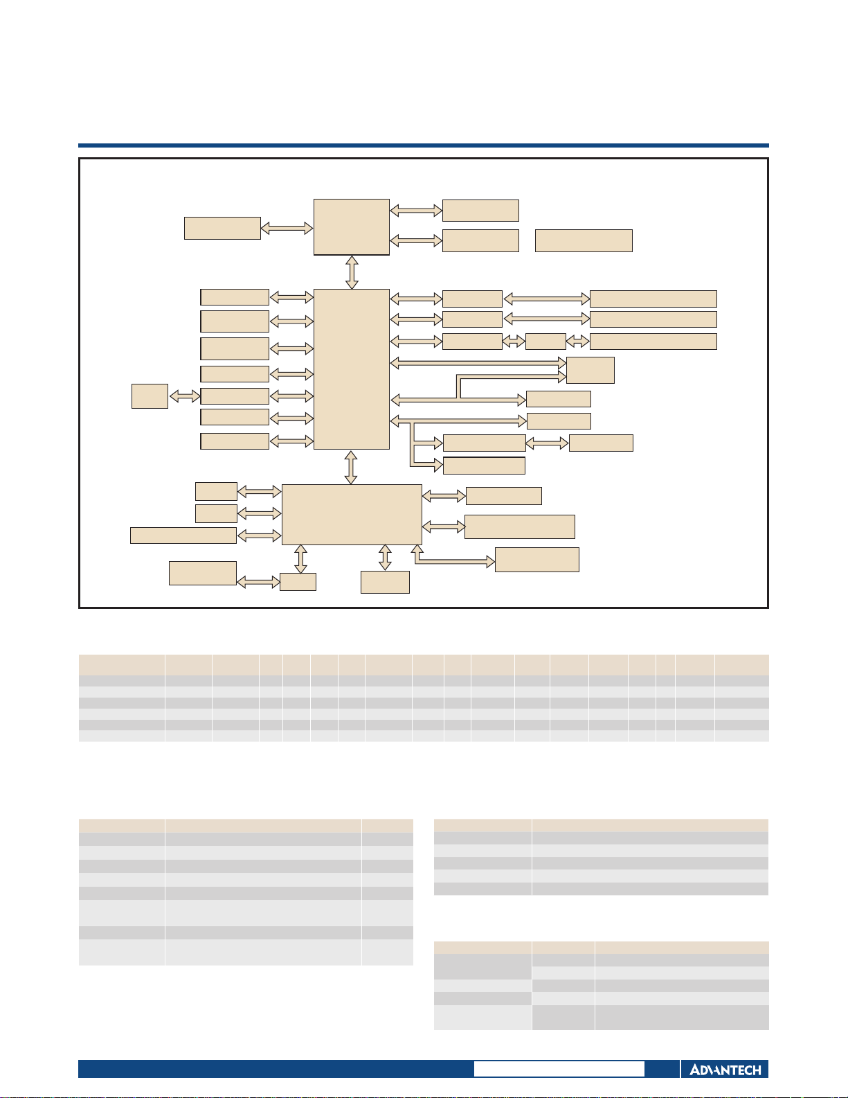
Board Diagram
18 bit LVDS
ALC888
SATAII x 3
Compact Flash
(Type-II)
16 Bits
GPIO
GPIO IC
SMBUS
BIOS
I2C
LVDS
HD
SATA
IDE
SPI
SMB
SMB
I2C
Intel N450/ D510
Processor
DMI x 4 (Up to 1GB/S)
Intel ICH8M
LPC
DDR2 667
GLCI
PCIe x 1
PCIe x 1
USB 2.0
VGA
DDR2
SODIMM x 1
Intel 82567V
Intel 82583V
Intel 82583V
PCIe x 1
PCI Bus
PCI to ISA bridge
PCI Slot
Watchdog Timer
MAXIM6369 (for IWD)
Isolator
Mini PCIe
USB 2.0 x 8
PCI-104
ISA Bus
PC/104
PCM-9562
GbE1
GbE2
GbE3 (Full version)
FAN1
FAN2
PS2 Keyboard/Mouse
COM6 (RS-232)
(Full version)
Isolator
LPC Super I/O
(SCH3106)
COM1/2/3
(RS-232)
LPT Port / FDD
COM4/5
(RS422/485)
(Share from COM2)
SIR
Ordering Information
Model CPU Memory VGA LVDS GbE1 GbE2
PCM-9562N-S6A1E Atom N450 SO-DIMM 1 18-bit 1 1 - Yes 8 1 3 2 Yes 1 1 Passive 0 ~ 60° C
PCM-9562D-S6A1E Atom D510 SO-DIMM 1 18-bit 1 1 - Yes 8 1 3 2 Ye s 1 1 Active 0 ~ 60° C
PCM-9562NF-S6A1E Atom N450 SO-DIMM 1 18-bit 1 1 1 Yes 8 2 3+1 2 Yes 1 1 Passive 0 ~ 60° C
PCM-9562DF-S6A1E Atom D510 SO-DIMM 1 18-bit 1 1 1 Yes 8 2 3+1 2 Yes 1 1 Active 0 ~ 60° C
PCM-9562NZ-1GS6A1E Atom N450 Bundle 1GB 1 18-bit 1 1 Optional Yes 8 1 3 2 Yes 1 1 Passive -20 ~ 80° C
PCM-9562Z2-1GS6A1E Atom N450 Bundle 1GB 1 18-bit 1 1 Optional Ye s 8 1 3 2 Yes 1 1 Passive -40 ~ 85° C
GbE3
UL60601
* PCM-9562NF-S6A1E and PCM-9562DF-S6A1E are designed with UL60601 isolation GbE3, COM6, and Watchdog Timer2
Both COM6 and GbE3 are optional by request for extended temperature products
Packing List
Part No. Description Quantity
9689000002 Mini Jumper Pack 1
2006956200 Startup Manual 1
2066956200 Utility CD 1
1700015741 ATX 5VSB cable 1
1960020569S000
1960046526N001 Cooler for PCM-9562D/DF (50 x 50 x 24 mm) 1
1960002379
PCM-9562 SBC 1
Heatsink for PCM-9562N/NF
(50 x 50 x 10 mm)
Heatsink for PCM-9562NZ/Z2
(50 x 50 x 30 mm)
1
1
HD
USB
Audio
2.0
Watchdog
Timer
RS-232
RS-422/
485
PC/104Plus
Mini
PCIe
CF Thermal
Optional Accessories
Part No. Description
PCM-10586-9562E Wiring kit for PCM-9562
1703100260 USB cable
CF-HDD-ADP CompactFlash 50-pin to IDE 44-pin adapter
170304015K AT cable 4P x 2/4200-H-4P 15 cm
1960049954N001 Heatspreader 157.4 x 100 x 24 mm
Embedded OS/API
Embedded OS/API Part No. Description
Win XPE
WES 7 2070009835 Image WES7E Intel Lunar v5.0 ENG
QNX 6.5
Software API 205E956000
2070009030 XPE WES2009 Luna Pier V4.0 ENG
2070009031 XPE WES2009 Luna Pier V4.0 MUI24
SUSI 3.0 SW API for PCM-9562
B:20091009 XP
Operating
Temperature
Online Download
www.advantech.com/products
Page 3

Value-Added Software Services
Software API: An interface that defines the ways by which an application program may request services from libraries and/or operating systems. Provides not only the underlying
drivers required but also a rich set of user-friendly, intelligent and integrated interfaces, which speeds development, enhances security and offers add-on value for Advantech platforms.
It plays the role of catalyst between developer and solution, and makes Advantech embedded platforms easier and simpler to adopt and operate with customer applications.
Software APIs
Control Monitor
General Purpose Input/Output is a flexible parallel interface
that allows a variety of custom connections. It allows users
to monitor the level of signal input or set the output status to
switch on/off a device. Our API also provides Programmable
GPIO
SMBus
I2C
GPIO, which allows developers to dynamically set the GPIO
input or output status.
SMBus is the System Management Bus defined by Intel®
Corporation in 1995. It is used in personal computers and
servers for low-speed system management communications.
The SMBus API allows a developer to interface a embedded
system environment and transfer serial messages using the
SMBus protocols, allowing multiple simultaneous device
control.
I2C is a bi-directional two wire bus that was developed by
Philips for use in their televisions in the 1980s.
The I2C API allows a developer to interface with an embedded
system environment and transfer serial messages using the I2C
protocols, allowing multiple simultaneous device control.
Watchdog
Hardware
Monitor
Hardware
Control
Display Power Saving
The Brightness Control API allows a developer to interface with
an embedded device to easily control brightness.
Brightness
Control
CPU Speed
A watchdog timer (WDT) is a device that performs a specific
operation after a certain period of time if something goes wrong
and the system does not recover on its own.
A watchdog timer can be programmed to perform a warm boot
(restarting the system) after a certain number of seconds.
The Hardware Monitor (HWM) API is a system health
supervision API that inspects certain condition indexes, such as
fan speed, temperature and voltage.
The Hardware Control API allows developers to set the PWM
(Pulse Width Modulation) value to adjust fan speed or other
devices; it can also be used to adjust the LCD brightness.
Make use of Intel SpeedStep technology to reduce power power
consumption. The system will automatically adjust the CPU
Speed depending on system loading.
Refers to a series of methods for reducing power consumption in
computers by lowering the clock frequency. These APIs allow the
user to lower the clock from 87.5% to 12.5%.
Backlight
The Backlight API allows a developer to control the backlight
(screen) on/off in an embedded device.
System
Throttling
Software Utilities
The BIOS Flash utility allows customers to update the flash
ROM BIOS version, or use it to back up current BIOS by
copying it from the flash chip to a file on customers’ disk. The
BIOS Flash utility also provides a command line version and
BIOS Flash
Embedded
Security ID
Monitoring
All product specifications are subject to change without notice Last updated : 9-May-2011
API for fast implementation into customized applications.
The embedded application is the most important property of
a system integrator. It contains valuable intellectual property,
design knowledge and innovation, but it is easily copied! The
Embedded Security ID utility provides reliable security functions
for customers to secure their application data within embedded
BIOS.
The Monitoring utility allows the customer to monitor system
health, including voltage, CPU and system temperature and fan
speed. These items are important to a device; if critical errors
happen and are not solved immediately, permanent damage may
be caused.
eSOS
Flash Lock
The eSOS is a small OS stored in BIOS ROM. It will boot up in
case of a main OS crash. It will diagnose the hardware status,
and then send an e-mail to a designated administrator. The
eSOS also provides remote connection: Telnet server and FTP
server, allowing the administrator to rescue the system.
Flash Lock is a mechanism that binds the board and CF card
(SQFlash) together. The user can “Lock” SQFlash via the Flash
Lock function and “Unlock” it via BIOS while booting. A locked
SQFlash cannot be read by any card reader or boot from other
platforms without a BIOS with the “Unlock” feature.
 Loading...