

Page 1

MAQ®20
Industrial Data Acquisition & Control System
Factory and Process Automation
Machine Automation
Military and Aerospace
Power and Energy
Environmental Monitoring
Oil and Gas
ETHERNET
USB
RS-232
RS-485
Page 2

Flexible, Powerful, High Performance...
MAQ®20 Industrial Data Acquisition & Control System
The MAQ®20 Industrial Data Acquisition and
Control System encompasses more than 25
years of design excellence and quality in the
process control industry. The initial offering in
this high performance and highly flexible system
is a family of DIN rail mounted, programmable,
multi-channel, industrially rugged signal
conditioning input and output modules and
communication modules. Each I/O module has
a 1500Vrms isolation barrier between field-
side and system-side wiring, and some models
offer per-channel isolation. All field wiring ter-
minals are heavily protected against overload,
accidental connection of incorrect signals, and
ESD. Modules mount on the industry standard
35x7.5mm gull-wing DIN rail, and a backbone
mounts within the rail providing power and
communication interconnections between the
communication modules and each I/O module.
One communication module can interface to
up to 24 I/O modules to construct a system
with a maximum of 384 channels that fits
within a standard 19” instrumentation rack!
Processors within each module make this
distributed system extremely powerful.
single-ended input for precise measure-
ment of voltage and current signals; they
also offer 8-channel measurement of five
thermocouple types including accurate cold
junction compensation and linearization.
All channels are individually configurable
for range, alarm limits, and averaging.
- RTD Input Modules interface to 2-wire,
3-wire, and 4-wire sensors including five
RTD types and potentiometers. Modules
offer six channels, each configurable for
range, alarm limits, and averaging.
- Strain Gage Input Modules connect to
full bridge sensors, have narrow or wide
bandwidth filtering and offer four channels,
each configurable for range, alarm limits,
and averaging.
- Frequency Input Module accepts zero-
crossing and TTL signals with frequencies
of 500Hz to 100kHz and provides a DC
stimulus for contact sensors. This module
has four channels, each configurable for
range and alarm limits.
• Analog Output Modules: Process Current
and Voltage Output models drive valves,
perform other crucial process operations,
and provide up to eight channels of output
which can be independently configured
• Discrete Input/Output Modules: Provide
multiple channels of input and output per
module and offer advanced special
functions as well as alarm capability
The System Backbone resides within the
DIN rail used for module mounting and pro-
vides power to and interface between the
communication module and the I/O modules.
Key MAQ®20 Features
• Wide Operating Temperature,
–40°C to +75°C
• Stability 50ppm/°C of Reading Typical
• 1500Vrms Channel-to-Bus Isolation
• 240Vrms Continuous Input Protection
• ANSI/IEEE C37.90.1 Transient Protection
• Graphical Control Software
The Modules:
• Communication Modules: Offered in
Ethernet, RS-232, RS-485, and USB with
host software interfaces to the system using
Modbus TCP or Modbus RTU protocol
• Analog Input Modules: Interface to a wide
range of standard industrial sensors and
equipment and offer up to 16 channels of
input, each of which can be independently
configured
- Process Voltage, Process Current &
Thermocouple Input Modules offer
8-channel differential input or 16-channel
Common MAQ®20 Features
I/O Field Connection 20 position terminal block
High density screw clamp, 16-28 AWG
Failsafe Features Watchdog Timer and Brownout Detection:
Resettouserdenedconguration
Dimensions (h)(w)(d)
I/O Modules
Communication Module
Environmental
Operating Temperature
Storage Temperature
Relative Humidity
Emissions, EN61000-6-4
Radiated, Conducted
Immunity EN61000-6-2
RF
ESD, EFT
Certications Heavy Industrial CE, ATEX Pending
Burn-in Qualication 48 hours at 75ºC, powered and loaded
4.51” x 0.60” x 3.26” (114.6mm x 15.3mm x 82.8mm)
4.51” x 1.11” x 3.26” (114.6mm x 28.2mm x 82.8mm)
–40°C to +75°C
–40°C to +85°C
0 to 95% Noncondensing
ISM Group 1
Class A
ISM Group 1
Performance A ±0.5% Span Error
Performance B
UL Class I, Division 2, Groups A, B, C, D Pending
Page 3
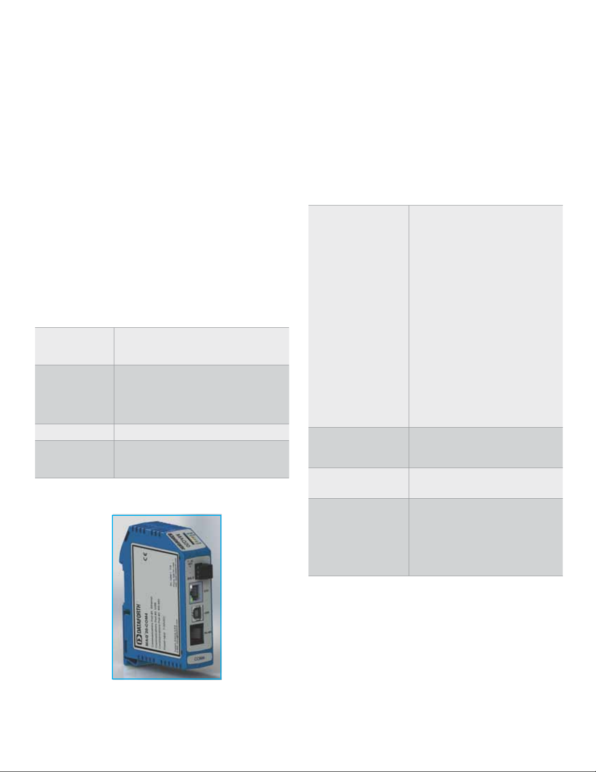
Communication Modules are offered in two models covering
standard industrial buses: Ethernet, RS-232, RS-485, and USB. Host
software interfaces to the system using the Modbus TCP or RTU
protocol. When using the Ethernet interface, up to four simultaneous
socket connections are supported and each socket can process up to
four simultaneous Modbus TCP transactions. Serial communications
over RS-232 or RS-485 can be run at baud rates as fast as 921.6kbps.
Another useful feature of the system is the capability to store acquired
data locally for later analysis. Each communication module has an easily
accessible and removable 4GB micro-SD memory card that can be
used to log data from all input modules.
To power the system, a 7-34VDC power source is connected to the
communication module. Regulated and protected supplies within the
module then provide power both to the internal circuits and to all mod-
ules in the system. When many high power I/O modules are used in a
system, load-sharing power boost modules can be installed in standard
I/O module slots to provide the necessary additional power.
Specications: Communication Modules
Typical at TA = +25°C and +24VDC system power
Analog Input Modules interface to a wide range of standard
industrial sensors and equipment, including volt, millivolt, milliamp,
thermocouple, RTD, potentiometer, strain gage and frequency. Four to
16 channels of input on the modules results in physically small control
systems and low cost per channel. Signal ranges are user selectable
and offered in both differential and single-ended configurations. Chan-
nels can be independently configured and alarms can be set to match
the most demanding applications.
Specications: Process Voltage, Process Current
& Thermocouple Input Modules
Typical at TA = +25°C and +24VDC system power
Model Number
MAQ20-MVDN
MAQ20-VDN
MAQ20-VSN
MAQ20-IDN
MAQ20-ISN
±2.0V, ±1.0V, ±250mV, ±100mV, ±50mV
Description
8-ch, mV, Differential Input
8-ch, V, Differential Input
16-ch, V, Single-Ended Input
±60V, ±40V, ±20V, ±10V, ±5V
8-ch, mA, Differential Input
16-ch, mA, Single-Ended Input
0-20mA or 4-20mA
Model Number
MAQ20-COM4
MAQ20-COM2
Communications
Ethernet
USB
RS-485
RS-232
Isolation 50V to bus
Power Supply
Input Power
Power to Bus
USB 2.0, Type B, Proprietary Modbus over USB
4-wire, up to 921.6kbps, RJ-12, Modbus RTU
Ethernet, USB, RS-485
Ethernet, USB, RS-232
10/100 Base-T, RJ-45, Modbus TCP
up to 921.6kbps, RJ-12, Modbus RTU
7-34VDC at 2A max
5VDC at 3A max
MAQ20-JTC
–100°C to +760°C, 3 selectable ranges
MAQ20-KTC
–100°C to +1350°C, 3 selectable ranges
MAQ20-TTC
–100°C to +400°C, 3 selectable ranges
MAQ20-RSTC
Per Channel Setup
CMR
NMR
Accuracy
mV, V, mA Input
TC Input
Bandwidth
Scan Rate
Alarms
Open Input Response
TC Input
Cold Junction Compensation
Accuracy, +25°C
Power Supply Current
(1) Includes linearity/conformity, hysteresis and repeatability. Does not include CJC accuracy.
(1)
Individuallycongurableforrange,alarmlimits,
8-ch, TC, Type J
8-ch, TC, Type K
8-ch, TC, Type T
8-ch, TC, Type R and Type S
0°C to +1750°C
averaging
100dB at 50Hz or 60Hz
30dB at 50Hz or 60Hz
±0.035% Span
±0.06% Span
3Hz
200 Ch/s
High / High-High / Low / Low-Low
Upscale, Flag set
±0.25°C
30mA
Communication Module
Page 4

Flexible Backbone System Allows 4, 8, 16 and/or 24 Module Conguration in
19” Rack Space
Specications: 2- or 3-Wire RTD & Potentiometer
Input Modules
Typical at TA = +25°C and +24VDC system power
Model Number
MAQ20-RTD31
MAQ20-RTD32
Number of Channels
Per Channel Setup
CMR
NMR
Accuracy
(1)
Bandwidth
Scan Rate
Alarms
Open Input Response
Power Supply Current
(1) Includes conformity, hysteresis and repeatability.
–200°Cto+850°C(100ΩPt),3selectableranges
0°Cto+850°C(100ΩPt),3selectableranges
–80°Cto+300°C(120ΩNi),3selectableranges
0Ωto5kΩ(Potentiometer),3selectableranges
–200°Cto+850°C(500ΩPt),3selectableranges
0°Cto+850°C(1000ΩPt),3selectableranges
0°Cto+160°C(10ΩCu)
0°Cto+160°C(50ΩCu)
6
Individuallycongurableforrange,
alarm limits, averaging
100dB at 50Hz or 60Hz
20dB at 50Hz or 60Hz
±0.06% Span
3Hz
200 Ch/s
High / High-High / Low / Low-Low
Upscale or Downscale
40mA
Specications: Strain Gage Input Modules - Preliminary
Typical at TA = +25°C and +24VDC system power
Model Number
MAQ20-BRDGN
MAQ20-BRDGW
Number of Channels
Per Channel Setup
Full bridge, Narrow bandwidth
Full bridge, Wide bandwidth
4
Individuallycongurableforrange,
alarm limits, averaging
Input Range
Excitation
CMR
NMR (MAQ20-BRDGN)
Accuracy
(1)
Bandwidth
Scan Rate
Alarms
Power Supply Current
(1) Includes linearity/conformity, hysteresis and repeatability.
±10mV to ±100mV
10.0V
100dB at 50Hz or 60Hz
20dB at 50Hz or 60Hz
±0.06% Span
3Hz, 3kHz
200 Ch/s for 3Hz model
High / High-High / Low / Low-Low
400mA
Specications: Frequency Input Modules - Preliminary
Typical at TA = +25°C and +24VDC system power
Model Number
MAQ20-FREQ 500Hz to 100kHz
Number of Channels
Per Channel Setup
Individuallycongurableforrange,
4
alarm limits
Zero Crossing Input
Min/Max Input
Hysteresis
Min Pulse Width
TTL Input
Min/Max Input
Hysteresis
Min Pulse Width
Excitation
100mVp-p/170Vp-p
±50mV
4µs
0.8V/2.4V
1.5V
4µs
+5V at 8mA
CMR 100dB at 50Hz or 60Hz
Accuracy
Scan Rate
Alarms
Power Supply Current
(1) Includes linearity/conformity, hysteresis and repeatability.
(1)
±0.05% Span
1500 Ch/s
High / High-High / Low / Low-Low
30mA
MAQ®20 Future Development
Controller Modules
CANbus
Wireless
Standalone
I/O Modules
True RMS Input
PID Loop Control
Single and Three Phase Monitoring
Ch-to-Ch Isolated Inputs
High Sample Rate / High Bandwidth Inputs
16 and 24 Bit Analog Input
DC and AC LVDT
Accelerometer Input
Two-Wire Transmitter Input
Serial Interface, RS-232 and RS-485
Interface to Existing Dataforth Signal Conditioning Modules
Page 5

Analog Output Process Current and Voltage Output
Modules are offered with 4-20mA and 0-20mA process current
output or up to ±10V voltage output with drive capability; they control
motors, drive valves and perform many other crucial process opera-
tions. Up to eight channels of output on the modules results in physi-
cally small control systems and low cost per channel. Output modules
have each field-side channel galvanically isolated from all others to
eliminate common mode signal problems and offer maximum durability.
Signal ranges are user selectable and channels can be independently
configured to match the most demanding applications. Processing
power within each module allows users to enter waveshapes to output
to field devices. Power-on delay and default channel states guarantee
proper process performance upon startup and during power interrup-
tions. Field I/O connections are made through a pluggable terminal
block with positions provided for the termination of wiring shields.
Specications: Analog Output Modules
Typical at TA = +25°C and +24VDC system power
Model Number
MAQ20-IO
MAQ20-VO
Number of Channels
Per Channel Setup
Over-range
MAQ20-IO
MAQ20-VO
Compliance
MAQ20-IO
Load Resistance Range
MAQ20-IO
Current Limit
MAQ20-IO
Output Drive (Max Load)
MAQ20-VO
Output Protection
Continuous
Transient
CMV
Channel-to-Channel
CMR
Accuracy
Bandwidth
Update Rate
Output Waveform
WaveformDenition
Update Rate
Power Supply Current
(1) Includes linearity/conformity, hysteresis and repeatability.
(1)
0-10V, 0-5V, 0-2.5V, ±10V, ±5V, ±2.5V
0-20mA or 4-20mA
8, isolated
Individuallycongurableforrange,
default output, waveform
21.5mA
10.5V
15V
0to600Ω
26mA
10mA(1000Ωat10V)
40Vrms max
ANSI/IEEE C37.90.1
300Vrms, 425VDC
75dB at 50Hz or 60Hz
±0.04% Span
100Hz
1600 Ch/s
100 points per channel
10ms for 8-ch
450mA
Discrete Input/Output Modules have multiple channels of
input and output per module. Solid state circuits provide or interface to
discrete signals up to 60V and 3A. In addition to standard discrete I/O,
these modules provide advanced special functions including Pulse/
Frequency Counter with or without de-bounce, Waveform Measure-
ment, Time Between Events, Frequency Generator, PWM Generator,
and One-Shot Pulse Generator. Alarms can be set on the discrete
input channels.
Specications: Discrete Input/Output Modules
Typical at TA = +25°C and +24VDC system power
Model Number
MAQ20-DIOL
MAQ20-DIOH
Number of Channels
Per Channel Setup
Input Protection
(Digital Input Channels)
Continuous
Transient
Output Protection
(Digital Output Channels)
Continuous
Transient
CMV
Channel-to-Channel
I/O Special Functions
Pulse/Frequency Counter
Pulse/Frequency Counter
with De-bounce
Waveform Measurement
Time Between Events
Frequency Generator
PWM Generator
One-Shot Pulse Generator
Alarms
Scan Rate
Power Supply Current 20mA
70VDC max, reverse polarity protected
70VDC max, reverse polarity protected
Freq to 10kHz, count to 10M, RPM to 65k
Freq to 50Hz, count to 10M, RPM to 65k
Freq to 500Hz at 1% accuracy, 10kHz at 21%
accuracy; # periods, pulse width, period, duty cycle
100µs min, programmable pre- and post-delay
3 to 60 VDC input
3 to 60 VDC output, 3A
90 to 280 VAC/VDC input
24 to 280 VAC output, 3A
5 discrete input, 5 discrete output
Individuallycongurableforspecial
function, default output
ANSI/IEEE C37.90.1
ANSI/IEEE C37.90.1
300Vrms, 425VDC
Min, max, avg, selectable timebase
Up to 700Hz at 1% accuracy,
10kHz at 14% accuracy
Selectable timebase
High / High-High / Low / Low-Low
3500 Ch/s
Discrete I/O Module
Page 6

The System Backbone resides within the DIN rail used for module
D
C
B
7
6
5
4
3
2
1
E
F
mounting and provides power to and interface between the commu-
nication module and the I/O modules. Standard backbones provide
for one communication module and 4, 8, 16, or 24 I/O modules. The
longest backbone, which accommodates 24 I/O modules, fits in an
industry standard 19” rack. Each backbone utilizes a pluggable con-
nector system on each end such that varying system channel counts
can be configured using the standard backbones. As a result of this
pluggable system, the main part of a system, including the commu-
nication module, can be installed in one location while other sets of
I/O modules installed in remote locations connect to the main system
through a wire harness.
Once a system is established with a system backbone and a com-
munication module, system configuration is accomplished by applying
power and installing the I/O modules. These are hot swappable and
true ‘plug and run’. When an I/O module is plugged into any backbone
position, the communication module automatically recognizes that it
has been added to the system, registers it in the system configuration
record, and makes it immediately available in the ReDAQ® Shape for
MAQ®20 host software for use in data acquisition and control. Simi-
larly, when a module is removed from any backbone position, the com-
munication module recognizes that it has been unplugged, removes it
from the system configuration, and disables it in the ReDAQ® Shape
for MAQ®20 software.
Specications: Backbone
Model Number
MAQ20-BKPL4
MAQ20-BKPL8
MAQ20-BKPL16
MAQ20-BKPL24
Expansion & Remote Location Male/Female pluggable terminal blocks
1 COM Module plus 4 I/O Modules
1 COM Module plus 8 I/O Modules
1 COM Module plus 16 I/O Modules
1 COM Module plus 24 I/O Modules
at each end of backbone allow system
expansion and distributed installation
Specications: Accessories
Model Number
MAQ20-XCA01
MAQ20-XCA02
SLX147-01, -02, -05
SLX141-01, -02, -07
SLX141-X01, -X02, -X07
PWR-PS5RB
PWR-PS5RC
PWR-PS5RD
PWR-PS5RE
SCMXRAIL1-XX
Power Supply, 24VDC, 0.6A, 100-240VAC Input, DIN Mount
Power Supply, 24VDC, 1.3A, 100-240VAC Input, DIN Mount
Power Supply, 24VDC, 2.1A, 100-240VAC Input, DIN Mount
Power Supply, 24VDC, 4.2A, 100-240VAC Input, DIN Mount
DIN EN50022-35x7.5 (slotted steel), length -xx, in meters
Backbone expansion cable, 1m
Backbone expansion cable, 2m
USB Cable, Type A to Type B, 1m, 2m, 5m
Ethernet Cable, 1m, 2m, 7m
Ethernet Crossover Cable, 1m, 2m, 7m
Specications: Boost Power Supply Module
Typical at TA = +25°C and +24VDC system power
Model Number
MAQ20-PWR3
Power Input 7-34VDC at 2A max
3-position pluggable terminal block
Power Output to Bus +5VDC at 3A
Comm Module with 4 I/O Modules on
DIN Rail Mounted Backbone
1.11in
28.2mm
SHLD
7-34
VDC
+
_
Front Thick Module
ETH.
USB
RS-485
Front Thin Module
.60in
15.3mm
4.51in
114.6mm
Side Both Modules
Dimensional Drawings
3.26in
82.8mm
Page 7

ReDAQ® Shape for MAQ®20 Software
Dataforth offers ReDAQ® Shape for MAQ®20
software as the easiest and most efficient devel-
opment tool for use with the MAQ®20 Industrial
Data Acquisition and Control System. This out-of-
the-box software enables users to create, save,
and open graphical user interface projects for test,
process, data collection and data analysis applica-
tions. Built-in functions in the Acquire and Analyze
panels are pre-configured and can be used with-
out setup. Just three easy steps are required to
create data acquisition and control projects using
18 high quality tools and powerful MAQ®20 func-
tions. These projects are developed and executed
in the software’s Presentation panel.
ReDAQ® Shape Toolbox Tools
– Button
– Picture Box
– Text Box
– Group Box
– Label
– LED
– Switch
– Numeric Edit
– Thermometer
– Slide
– Tank
– Gage
– Meter
– Knob
– Chart Recorder
– Oscilloscope
– XY Plot
– Discrete Waveform Graph
ReDAQ® Shape for MAQ®20 software also
provides the most effective way to configure and
customize MAQ®20 functions for specific applica-
tion requirements. The toolbox tools are easily
moved, re-sized, cut, copied, pasted, and deleted.
®
The main screen of ReDAQ
shows a representation of the system inclusive
of the communication module and any installed
I/O modules. This graphic is updated as I/O mod-
ules are added to or removed from the system.
Modules can be given unique identifiers, and I/O
module channels can be assigned tag names to
represent process variables they control. These
Shape for MAQ®20
identifiers and tag names are propagated
throughout the software anytime these modules
and signals are used.
In contrast to other graphical software environ-
ments, ReDAQ® Shape for MAQ®20 software
has a very short user-learning curve. It is
based on programming tools incorporated from
Microsoft Visual Studio® and National Instruments
Measurement StudioTM, ensuring its ease of use
and integrated, across-the-board applicability for
data acquisition and control applications.
MAQ®20 Functions
– Continuous and burst scan modes
– Automatically scales data from counts to engineering units
– Discrete I/O offers special functions: pulse/frequency counter, pulse/frequency counter
with de-bounce, waveform measurement, time between events, frequency generator,
PWM generator, and one-shot pulse generator
– Customer user tag name for any input and output
– Control loop and alarm output
– Three function timer (count-down, 24hr/day, or day/time) with 10 programmable events
Acquire
Analyze
Present
Page 8

WORLD HEADQUARTERS
Dataforth Corporation
3331 E. Hemisphere Loop
Tucson, AZ 85706 USA
Toll Free: 800-444-7644
Tel: 520-741-1404
Fax: 520-741-0762
Email: sales@dataforth.com
www.dataforth.com
Dataforth Europe
Tel: +49.8631.308111
Fax: +49.8631.308118
Email: datafortheurope@dataforth.eu
www.dataforth.eu
High Performance Industrial Signal Conditioning, Data Acquisition,
and Data Communication Products Since 1984
Dataforth Asia
Tel: 949-829-3678
Email: dataforthasia@dataforth.com
www.dataforth.com.cn
The Dataforth Quality
Management System is
ISO9001:2008 Registered
www.dataforth.com
©2012 Dataforth Corporation, All Rights Reserved ISO9001:2008-Registered QMS MAR-145 04/12
 Loading...