

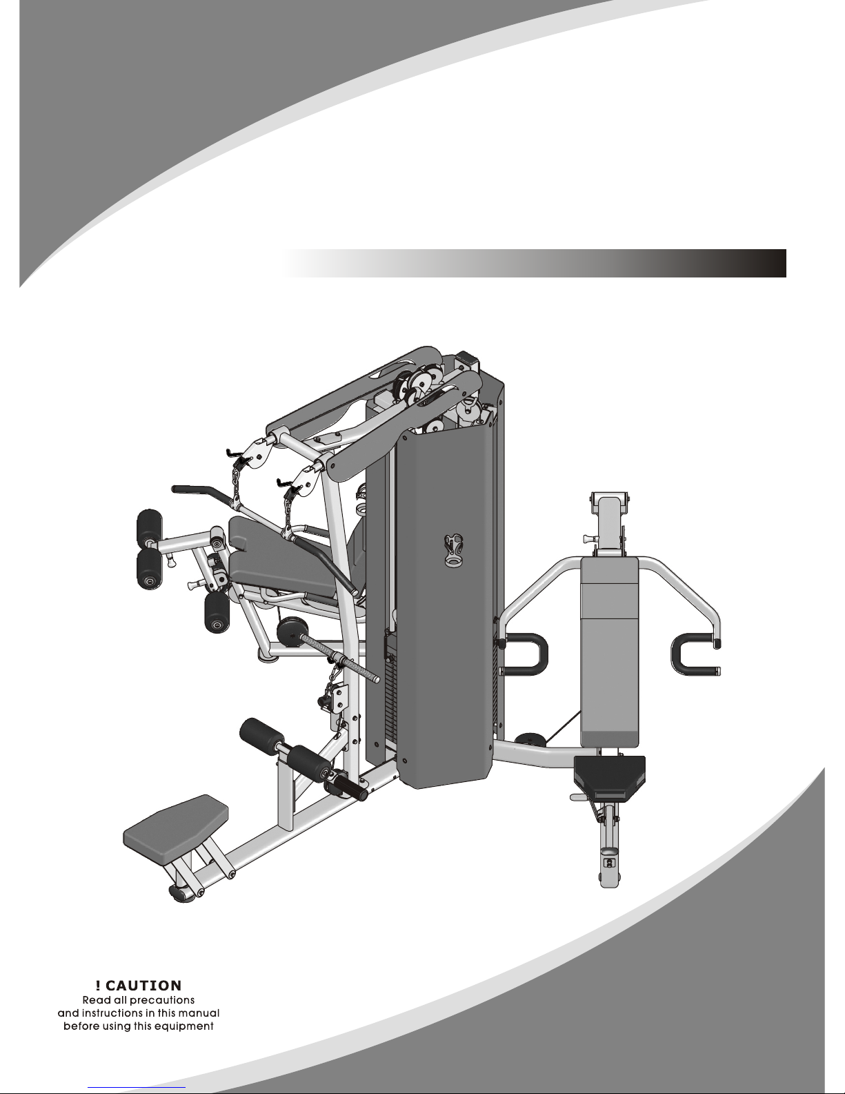
OWNER'S MANUAL
13 W
3 STACK MULTI-STAT I O N
ES3000ES3000

Table Of Contents
Read all precautions and instructions in this manual before using this
equipment.
! CAUTION
Important Safety Instructions------------------------------------------------------------ 3
Instructions----------------------------------------------------------------------------------- 4
Measurement Guide------------------------------------------------------------------------ 5
Assembly Instructions---------------------------------------------------------------------- 6
Leg Extension / Leg Cur--------------------------------------------------------------- 7
Exploded View and Parts List------------------------------------------------------------- 8
Assembly------------------------------------------------------------------------------------- 16
Multi Press------------------------------------------------------------------------------ 23
Exploded View and Parts List----------------------------------------------------------- 24
Assembly------------------------------------------------------------------------------------- 38
Lat Pulldown / Vertical Row-------------------------------------------------------- 45
Exploded View and Parts List----------------------------------------------------------- 46
Assembly------------------------------------------------------------------------------------- 62
Maintenance Schedule------------------------------------------------------------------- 73
General Maintenance Information---------------------------------------------------- 74
Weight Training Tips---------------------------------------------------------------------- 75

─ 3 ─
Important Safety Instructions
Before beginning any fitness program, you should obtain a complete
physical examination from your physician. When using exercise equipment,
basic precautions should always be taken, including the following:
* Read all instructions before using the equipment. These instructions are
written to ensure your safety and to protect the unit.
* Do not allow children on or near the equipment.
* Use the equipment only for its intended purpose as described in this guide.
Do not use accessory attachments that are not recommended by the
manufacturer: such attachments might cause injuries.
* Wear proper exercise clothing and shoes for your workout----no loose
clothing.
* Be careful when getting on or off the equipment.
* Do not overexert yourself or work to exhaustion.
* If you feel any pain or abnormal symptoms, stop your workout immediately
and consult your physician.
* Never operate the unit when it has been dropped or damaged.
* Never drop or insert anything into any opening in the equipment.
* Always check the unit and its cables before each use. Make sure that all
fasteners and cables are secure and in good working condition.
* Frayed or worn cables can be dangerous and may cause injury. Periodically
check these cables for any indication of wear.
* Keep hands, limbs, loose clothing and long hair well out of the way of
moving parts.
* Do not attempt to lift more weight than you can control safely.
* Do not use the equipment outdoors.
PERSONAL SAFETY DURING ASSEMBLY
* Read each step in the assembly instructions and follow the steps in
sequence. Do not skip ahead. If you skip ahead, you may learn later that you
have to disassemble components and that you may have damaged the
equipment.
* Assemble and operate the equipment on a solid, level surface. Locate the
unit a few feet from walls or furniture to provide easy access. The
equipment is designed for your enjoyment. By following these precautions
and using common sense, you will have many safe and pleasurable hours
of healthful exercise with the equipment.
Instructions
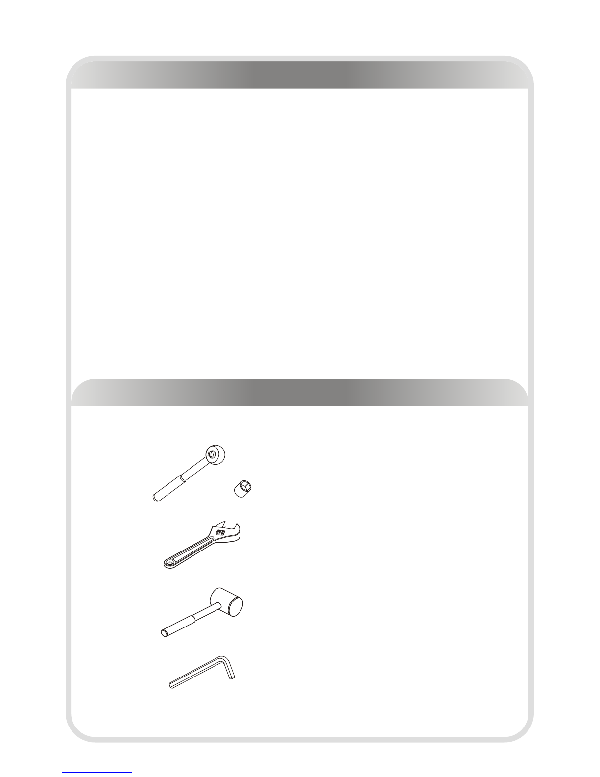
Tools Required
─ 4 ─
Before beginning assembly please take the time to read instructions
thoroughly. Please use the various lists in this manual to make sure that all
parts have been included in your shipment. When ordering, use part number
and description from the lists. Use only our replacement part when servicing.
Failure to do so will void your warranty and could result in personal injury.
The equipment is designed to provide the smoothest, most effective exercise
motion possible. After assembly, you should check all functions to ensure
correct operation. If you experience problems, first recheck the assembly
instructions to locate any possible errors made during assembly. If you are
unable to correct the problem, call your authorized dealer. Be sure to have
your serial number and this manual when calling. When all parts have been
accounted for, continue on.
Ratchet Wrench and Socket
Adjustable Wrench
Rubber Mallet
Hex Key Wrench Set

─ 5 ─
Inches
Millimeters
BHCS = Button Head Cap Screw
SHCS = Socket Head Cap Screw
FHCS = Flat Head Cap Screw
HHB = Hex Head Bolt
Measurement Guide
─ 6 ─
Assembly Instructions
Assembly of the equipment takes professional installers about 2 hours. If this
is the first time you have assembled this type of equipment, plan to spend
more time. It is strongly recommended to assemble the equipment by
professional installers. You may find it quicker, safer, easier to assemble this
equipment with the help of a friend, as some of components may be large,
heavy or awkward to handle alone. It is important that you assemble your
product in a clean, clear, uncluttered area. This will enable you to move around
the product while you are fitting components and reduce the possibility of
injury during assembly.
As with any assembled part, proper alignment and adjustment is critical. While
tightening the fasteners, be sure to leave room for adjustments. Do not fully
tighten the fasteners until instructed to do so. Be careful to assemble the
components in the sequence presented in this guide.
NOTE

─ 7 ─
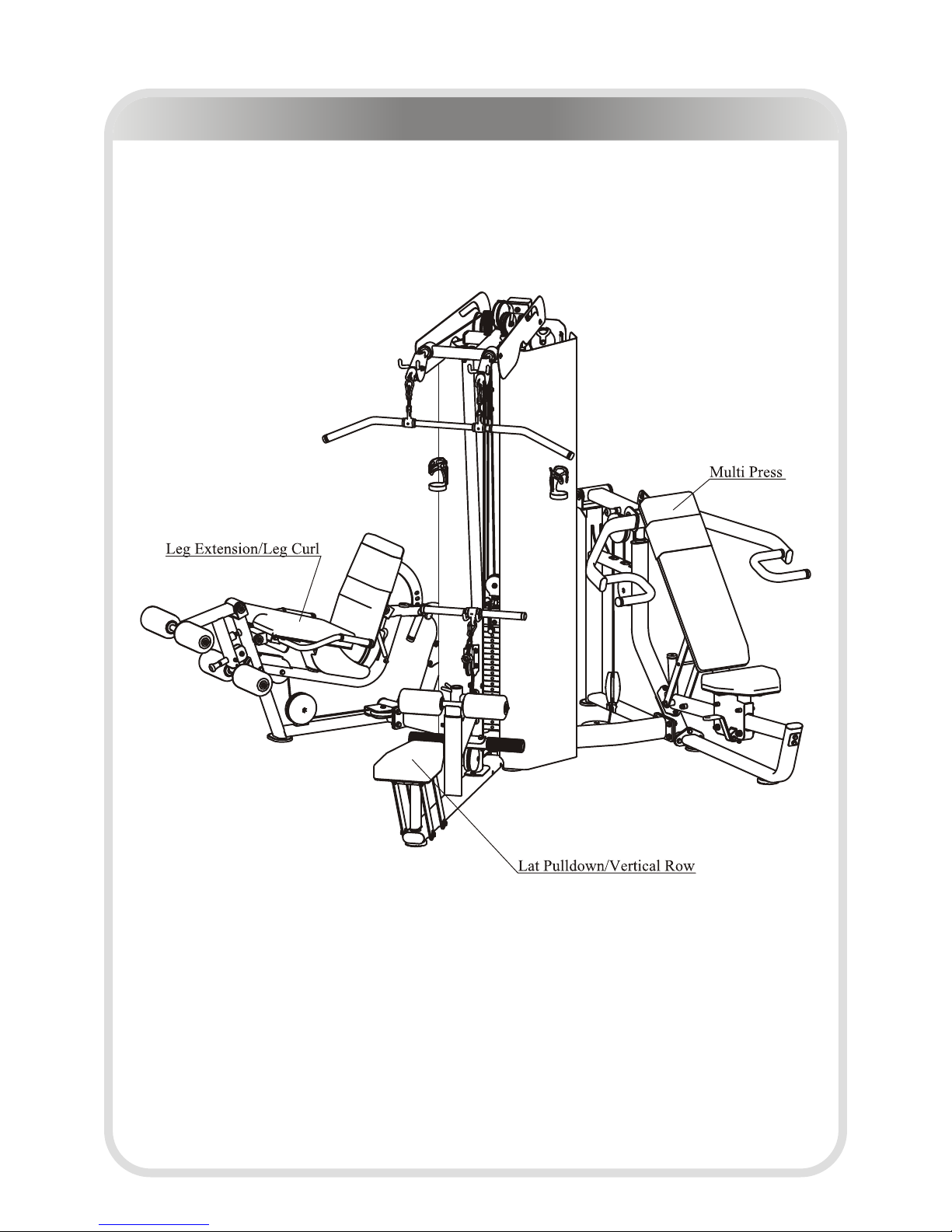
Leg Extension / Leg Curl
Leg Extension / Leg Curl -------- P7-22
─ 8 ─
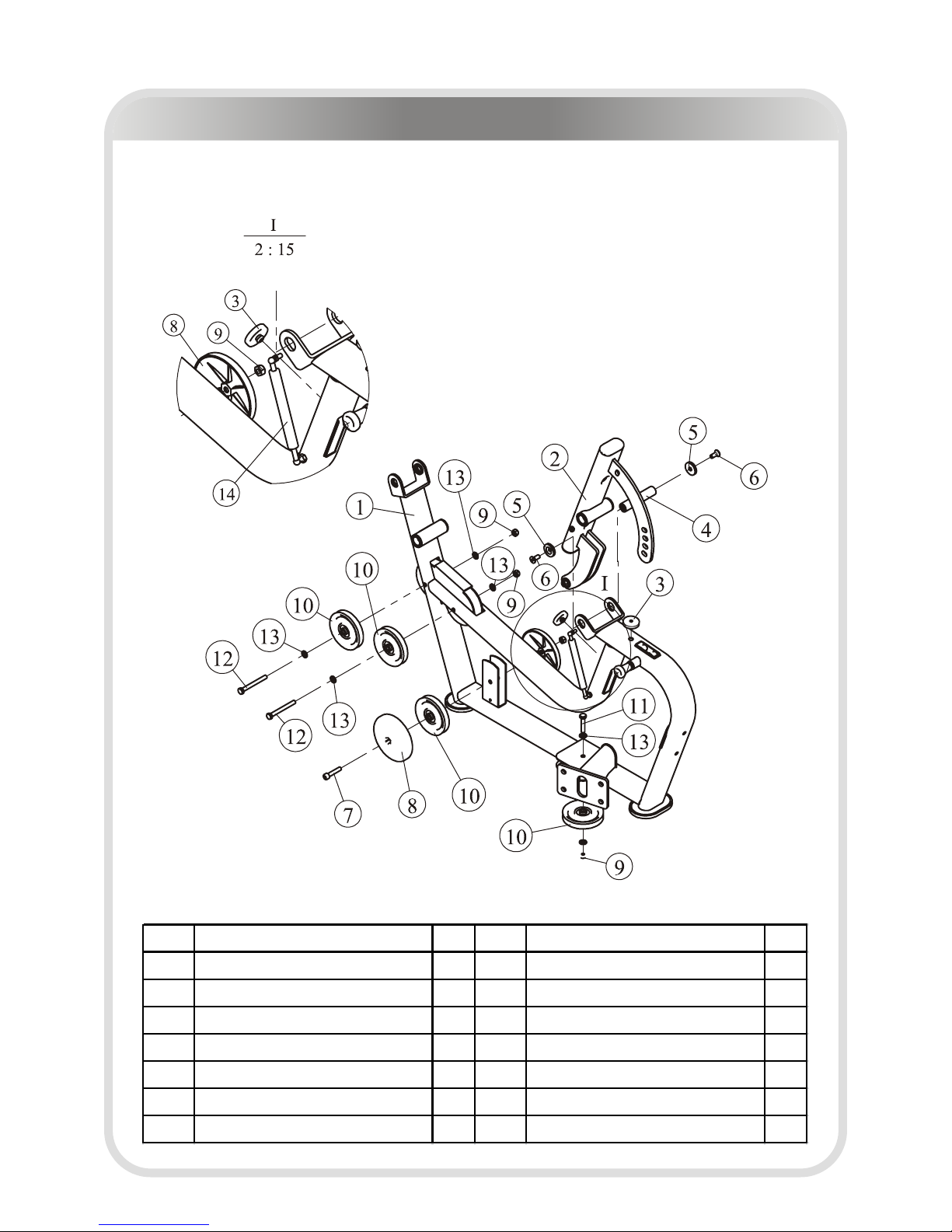
Main Frame And Back Pad Frame ASSY
ITEM NO.
Description QTY
ITEM NO.
Description QTY
1 Main Frame ASSY 1 8 Cover for 4.5" Pulley 2
2 Back Pad Frame ASSY 1 9 Nylon Lock Nut M10 4
3 Cushion 2 10 4.5" Pulley 4
4 Shaft Φ25.4*120 1 11 Hex Head Bolt M10*50 1
5 End Cap Φ38*Φ11*6 2 12 Hex Head Bolt M10*95 2
6 Flat Head Cap Sc rew M10*25 2 13 Flat Washer Φ11*Φ20*2 6
7 Socket Head Cap Sc rew M10*50 1 14 Gas Spring 1
Leg Extension / Leg Curl Exploded View and Parts List
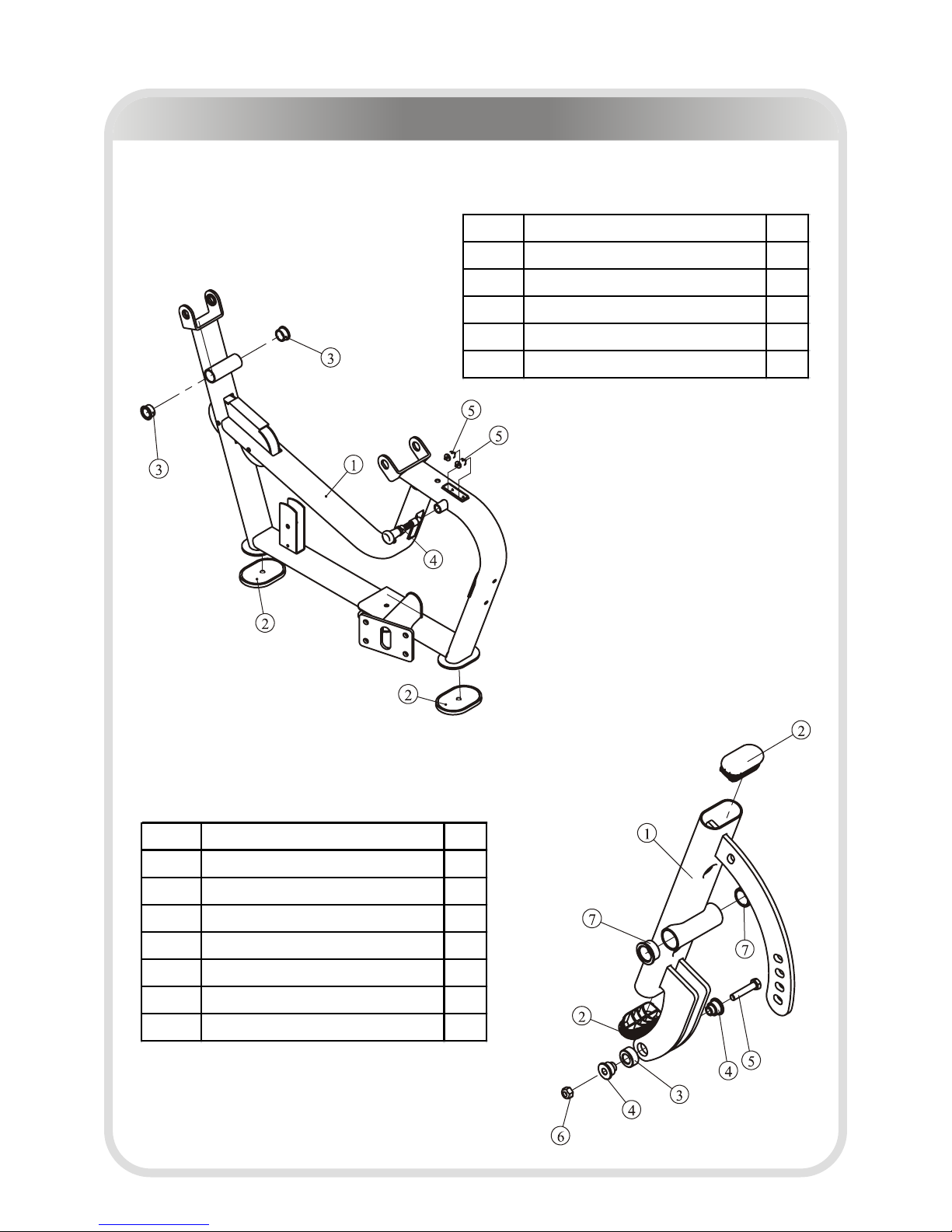
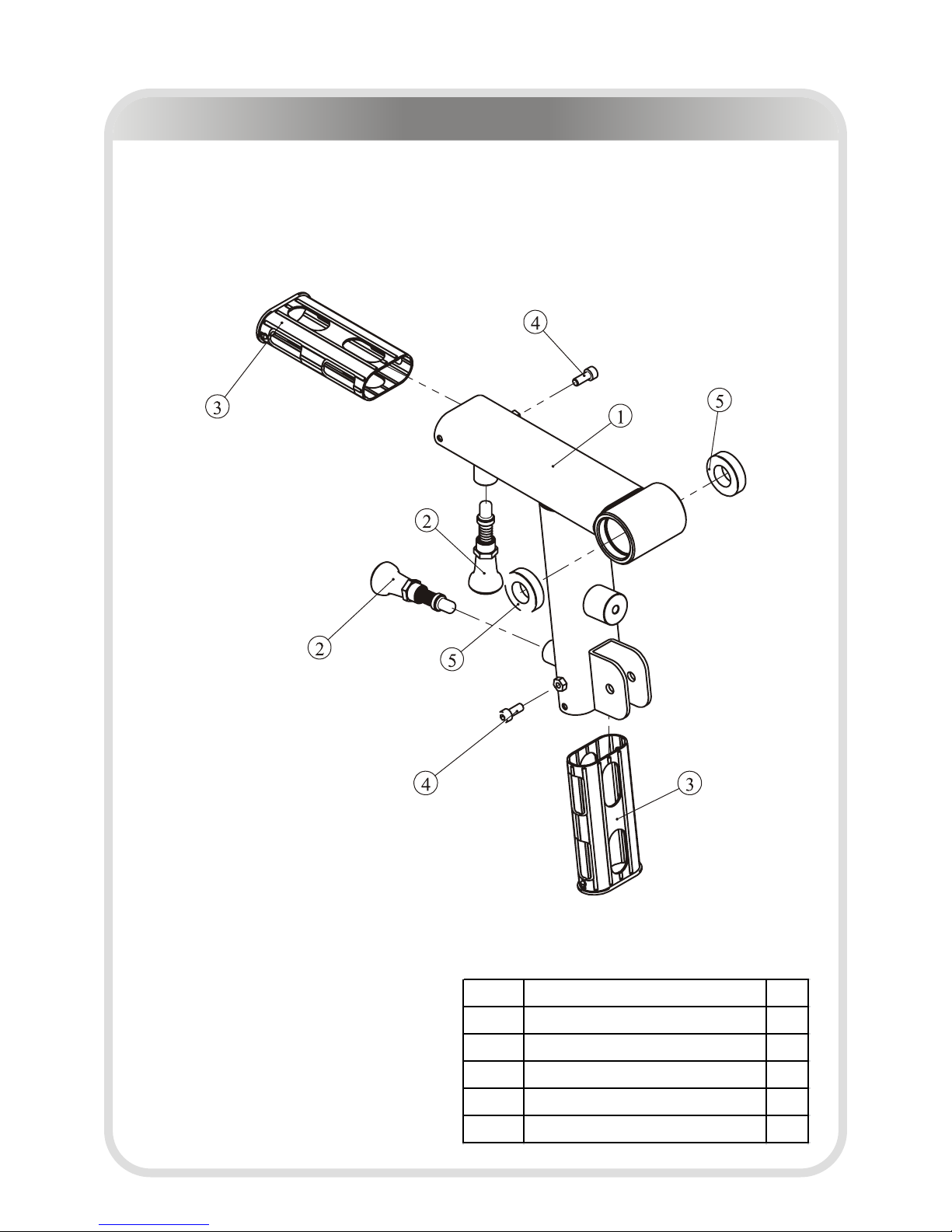
Main Frame ASSY
ITEM NO.
Description QTY
1 Main Frame 1
2 Foot Pad 2
3 Coppery Spacer 2
4 Pin 1
5 Nylon Pad 4
ITEM NO.
Description QTY
1 Back Pad Frame 1
2 Plug RT40*80 2
3 Shaft 1
4 Shaft Bush 2
5 Hex Head Bolt M10*50 1
6 Nylon Lock Nut M10 1
7 Coppery Spacer 2
Back Pad Frame ASSY
Leg Extension / Leg Curl Exploded View and Parts List
─ 9 ─
─ 10 ─
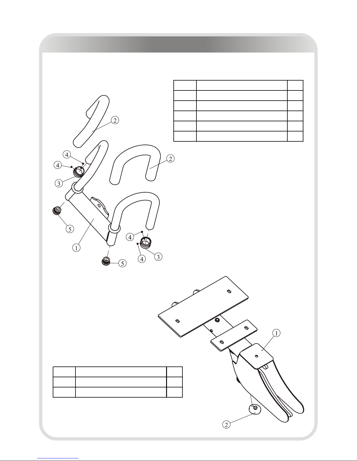
Front Handle Frame ASSY
ITEM NO.
Description QTY
1 Front Handle Frame 1
2 Grip ST Φ30*Φ22*390 2
3 Aluminium Grip Cap Φ25 2
4 Socket Set Screw 10-32*3.2 4
5 Plug Φ25 2
Seat Pad Frame ASSY
ITEM NO.
Description QTY
1 Seat Pad Frame 1
2 Cushion 1
Leg Extension / Leg Curl Exploded View and Parts List
─ 11 ─
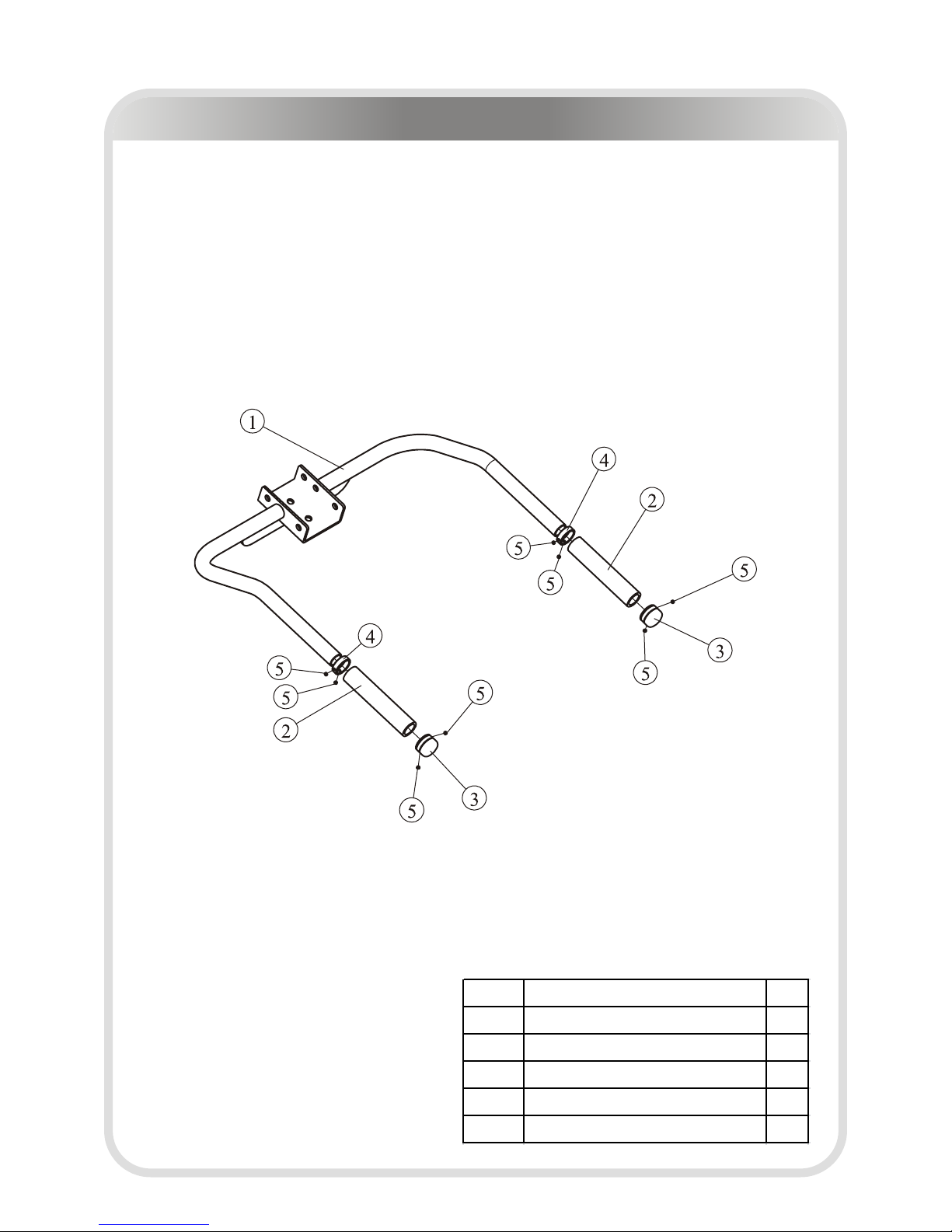
Rear Handle Frame ASSY
ITEM NO.
Description QTY
1 Rear Handle Frame 1
2 Grip STΦ30*Φ22*390 2
3 Aluminium Grip Cap Φ25 2
4 Aluminium Grip Ring Φ25 2
5 Socket Set Screw 10-32*3.2 8
Leg Extension / Leg Curl Exploded View and Parts List
─ 12 ─
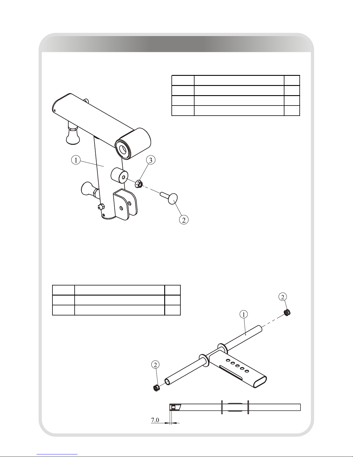
Rear Swing Frame II ASSY
FOAM Frame ASSY
ITEM NO.
Description QTY
1 FOAM Frame 2
2 Nut 2
Leg Extension / Leg Curl Exploded View and Parts List
ITEM NO.
Description QTY
1 Rear Swing Frame Ⅰ ASSY 1
2 Adjustment Screw 1
3 Flange Nut 1
─ 13 ─
Rear Swing Frame I ASSY
ITEM NO.
Description QTY
1 Rear Swing Frame 1
2 Pin 2
3 Plastic Tube Guide 2
4 Socket Head Cap Sc rew M8*20 2
5 Bearing 2
Leg Extension / Leg Curl Exploded View and Parts List
─ 14 ─
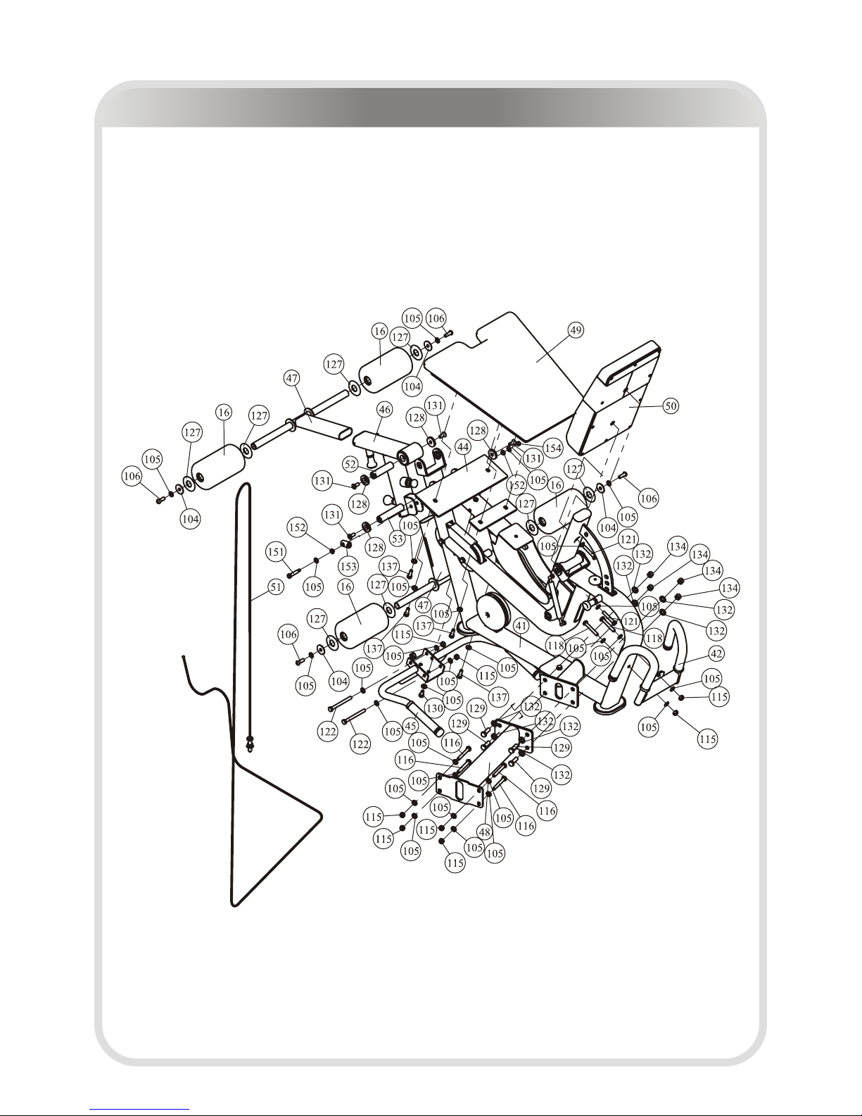
Overall
Leg Extension / Leg Curl Exploded View and Parts List
ITEM NO. Description QTY
41 Main Frame And Back Pad Frame ASSY 1
42 Front Handle Frame ASSY 1
44 Seat Pad Frame ASSY 1
45 Rear Handle Frame ASSY 1
46 Rear Swing Frame Ⅱ ASSY 1
47 FOAM Frame ASSY 2
48 Junction Frame 1
51 Cable 3 1
52 Shaft Φ25*100*M10 1
53 Shaft Φ25.4*120*M10 1
29 Top Plate 3
104 Washer Φ11*Φ38*2 4
105 Flat Washer Φ11*Φ20*2 29
106 Button Head Cap Screw M10*30 4
115 Nylon lock Nut M10 8
116 Hex Head Bolt M10*75 4
118 Hex Head Bolt M10*65 2
120 Hex Head Bolt M10*20 1
121 Hex Head Bolt M10*60 2
122 Hex Head Bolt M10*105 2
127 Plastic Washer Φ60*Φ25.7*3 8
128 End Cap 4
129 Hex Head Bolt M12*35 4
131 Flat Head Cap Screw M10*25 4
132 Flat Washer Φ13*Φ24*1.5 8
134 Nylon lock Nut M12 4
137 Hex Head Bolt M10*30 4
151 Shoulder BoltΦ10*40*M8 1
152 Spacer Φ10.2*Φ14*6 2
153 Cable End 1
154 Nylon Lock Nut M8 1
─ 15 ─
Overall
Leg Extension / Leg Curl Exploded View and Parts List
─ 16 ─
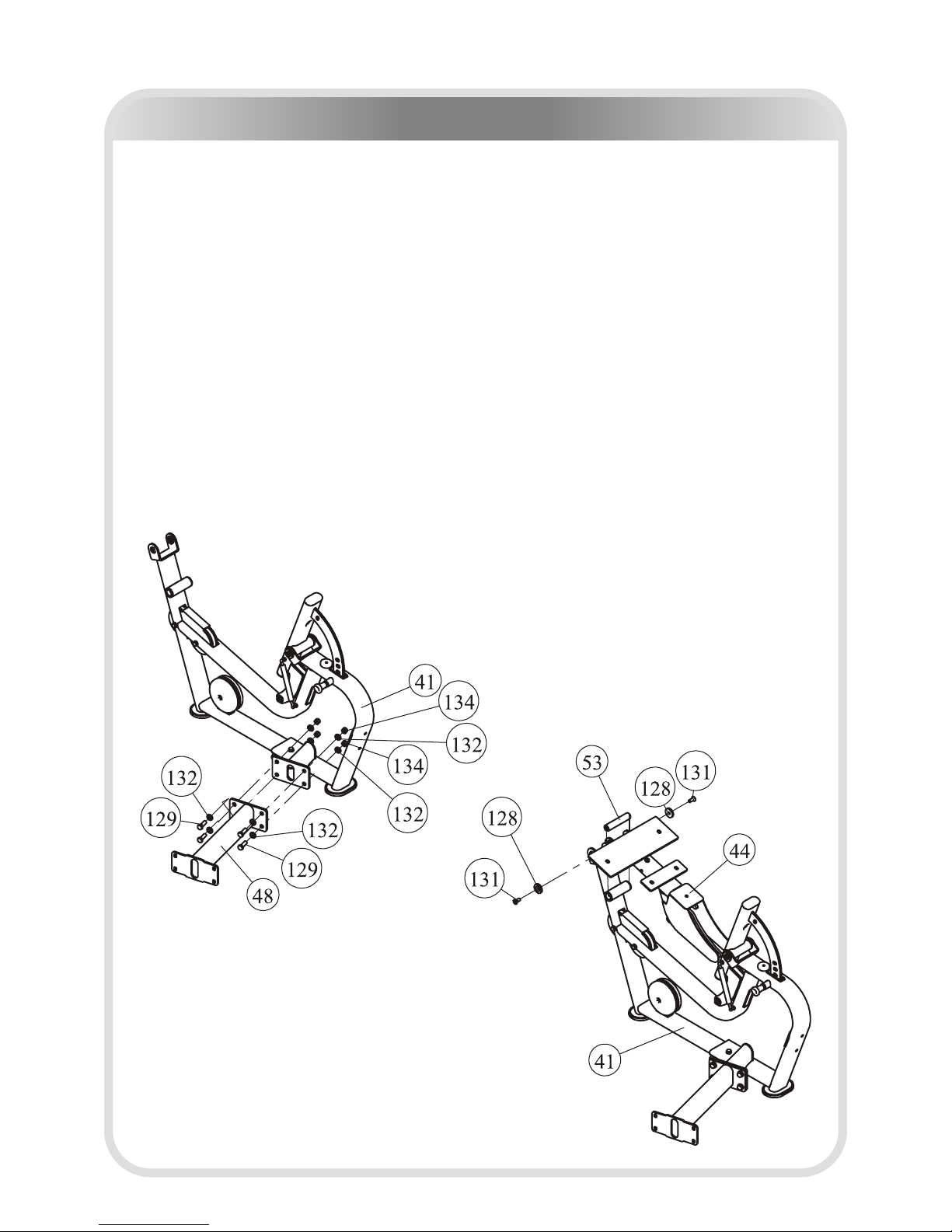
Leg Extension / Leg Curl Assembly
Attach the Junction Frame (#48) to Main Frame And Back Pad Frame ASSY (#41),
using:
● four M12*35 Hex Head Bolt (#129)
● four M12 Nylon Lock Nut (#134)
● eight Φ13*Φ24*1.5 Flat Washer (#132)
Note: Wrench Tighten Bolts and Nylon Lock Nuts.
Attach the Seat Pad Frame ASSY (#44) to Main Frame And Back Pad Frame ASSY
(#41), using:
● two M10*25 Flat Head Cap Screw (#131)
● two End Cap (#128)
● one Φ25.4*120*M10 Shaft (#53)
Note: Wrench Tighten Bolts and Nylon Lock Nuts.
STEP 1
STEP 1
STEP 2
STEP 2
─ 17 ─
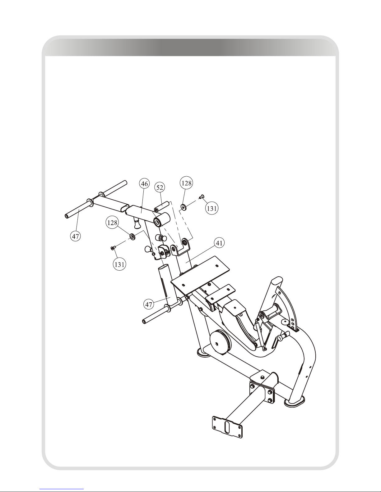
STEP 3
1. Attach the Rear Swing Frame II ASSY (#46) to Main Frame And Back Pad Frame
ASSY (#41), using:
● two M10*25 Flat Head Cap Screw (#131)
● two End Cap (#128)
● one Φ25.4*100*M10 Shaft (#52)
Note: Wrench Tighten Bolts and Nylon Lock Nuts.
2. Attach two FOAM Frame ASSY (#47) to the Rear Swing Frame II ASSY (#46).
Leg Extension / Leg Curl Assembly
─ 18 ─
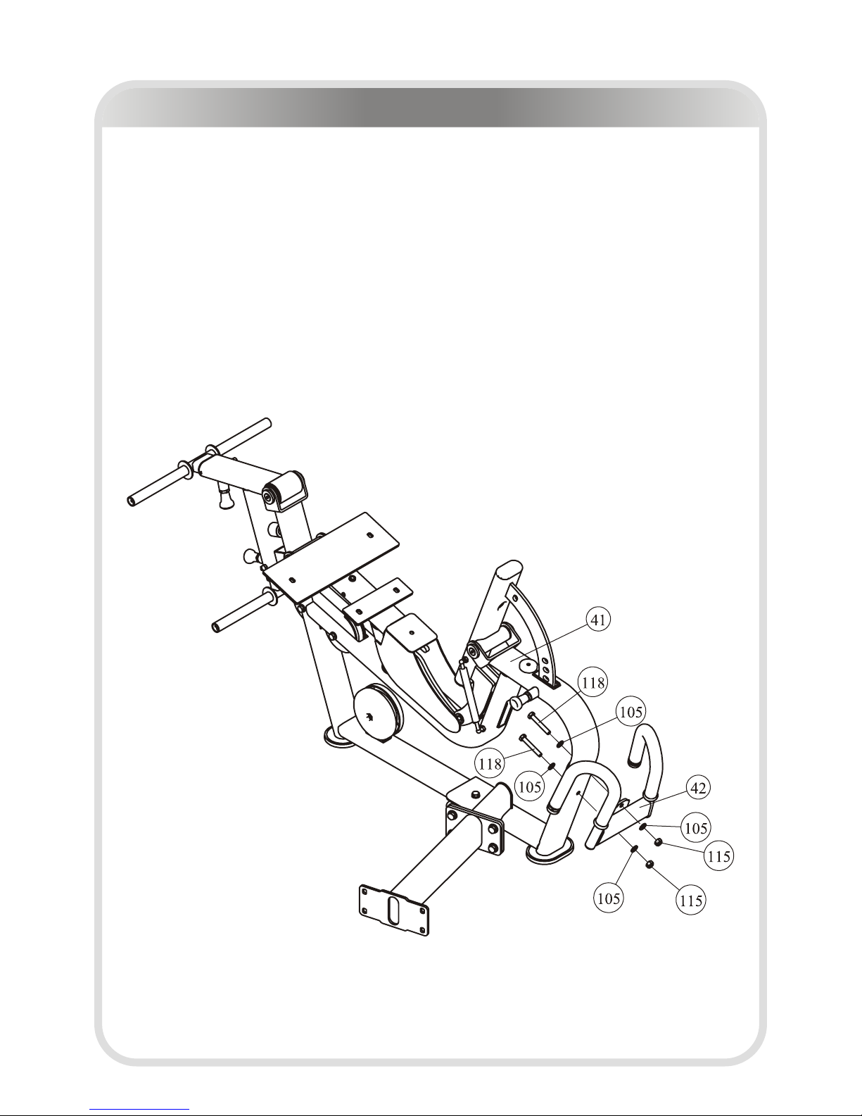
STEP 4
Attach the Front Handle Frame ASSY (#42) to Main Frame And Back Pad Frame
ASSY (#41), using:
● two M10*65 Hex Head Bolt (#118)
● two M10 Nylon Lock Nut (#115)
● four Φ11*Φ20*2 Flat Washer (#105)
Note: Wrench Tighten Bolts and Nylon Lock Nuts.
Leg Extension / Leg Curl Assembly
─ 19 ─
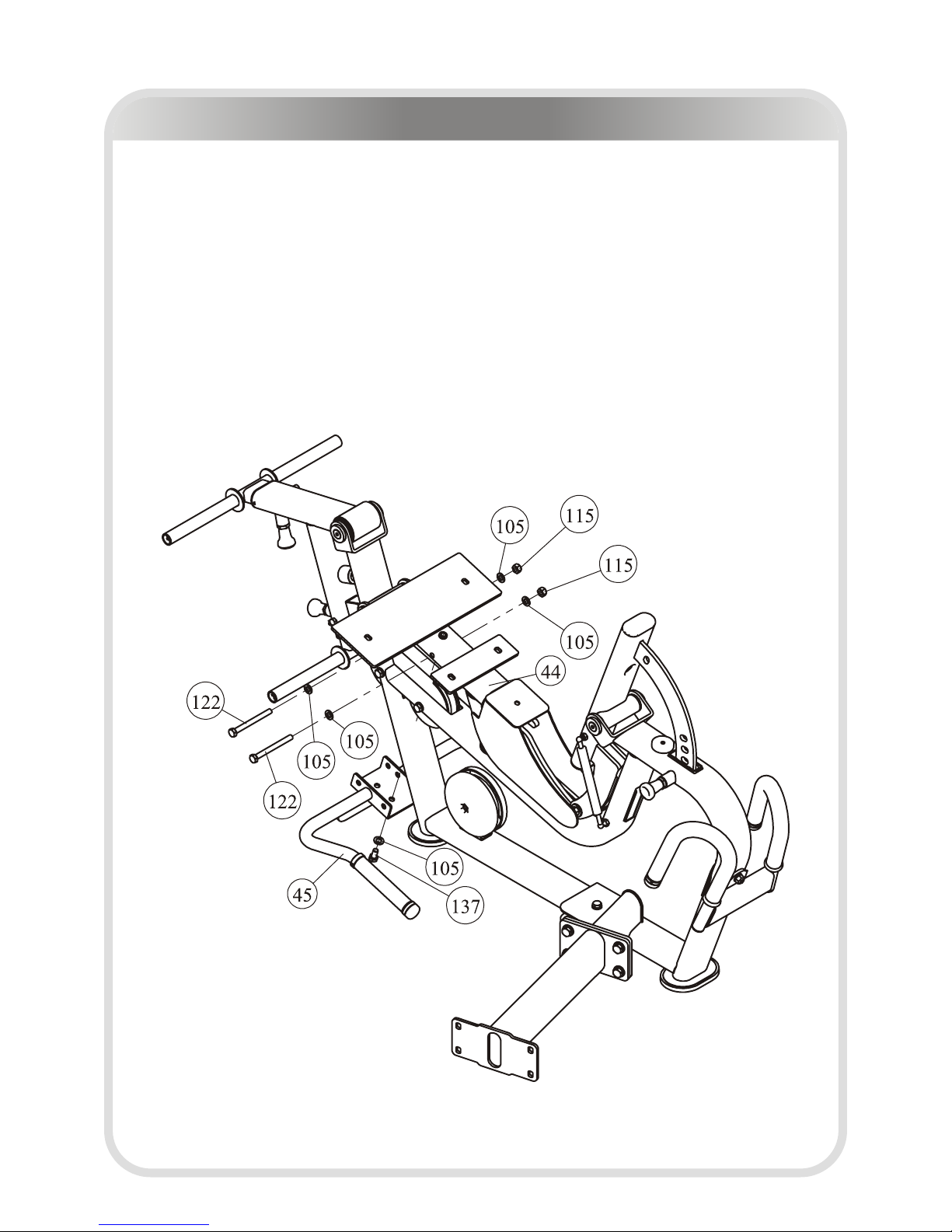
STEP 5
Attach the Rear Handle Frame ASSY (#45) to Seat Pad Frame ASSY (#44), using:
● two M10*105 Hex Head Bolt (#122)
● two M10 Nylon Lock Nut (#115)
● five Φ11*Φ20*2 Flat Washer (#105)
● one M10*30 Hex Head Bolt (#137)
Note: Wrench Tighten Bolts and Nylon Lock Nuts.
Leg Extension / Leg Curl Assembly
─ 20 ─
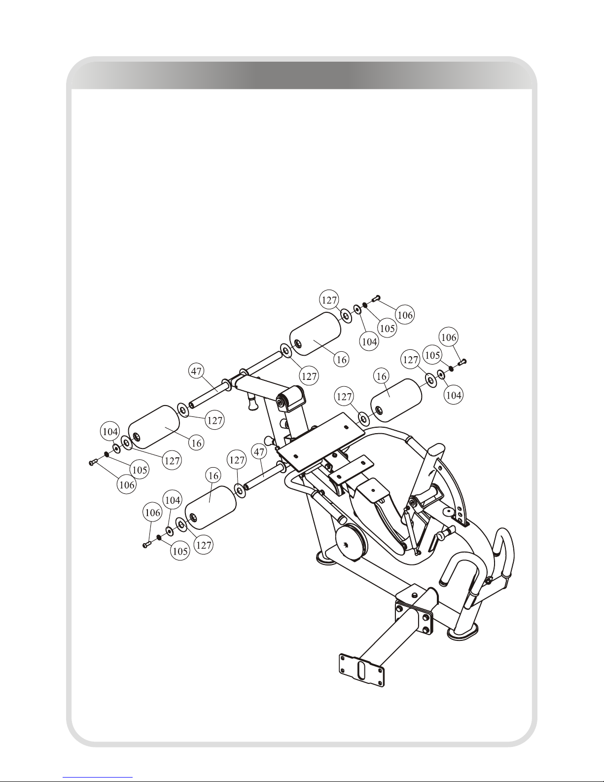
STEP 6
Attach four FOAM (#16) to two FOAM Frame ASSY (#47), using:
● four M10*30 Button Head Cap Screw (#106)
● four Φ11*Φ38*2 Washer (#104)
● four Φ11*Φ20*2 Flat Washer (#105)
● eight Φ60*Φ25.7*3 Plastic Washer (#127)
Note: Wrench Tighten Bolts and Nylon Lock Nuts.
Leg Extension / Leg Curl Assembly
─ 21 ─
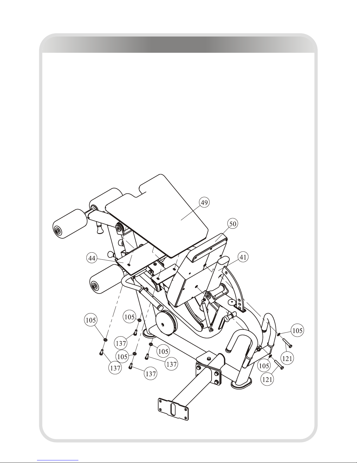
STEP 7
1. Attach Seat Pad (#49) to Seat Pad Frame ASSY (#44), using:
● four M10*30 Hex Head Bolt (#137)
● four Φ11*Φ20*2 Flat Washer (#105)
2. Attach Back Pad (#50) to Main Frame And Back Pad Frame ASSY (#41), using:
● two M10*60 Hex Head Bolt (#121)
● two Φ11*Φ20*2 Flat Washer (#105)
Note: Wrench Tighten Bolts and Nylon Lock Nuts.
Leg Extension / Leg Curl Assembly
─ 22 ─
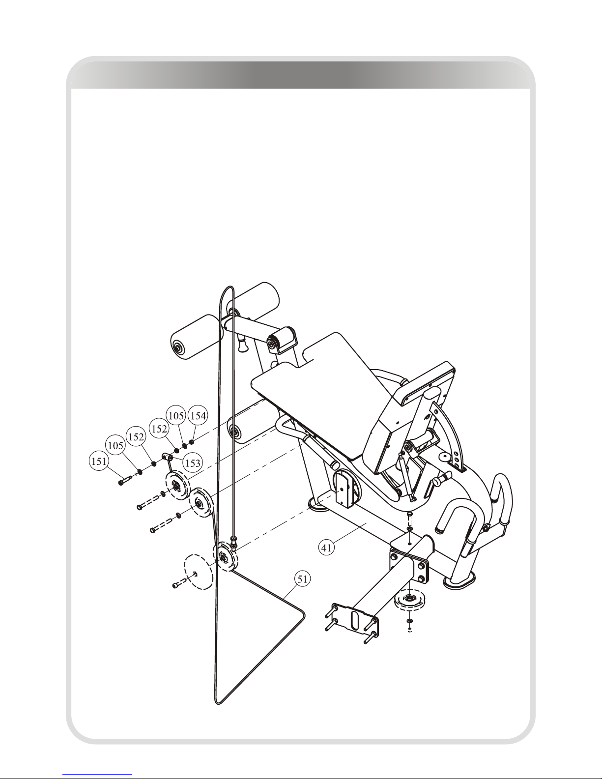
STEP 8
Attach the Cable (#49) to Main Frame And Back Pad Frame ASSY (#41), and go
through four 4.5" Pulley. Using:
● one Φ10*40*M8 Shoulder Bolt (#151)
● two Φ10.2*Φ14*6 Spacer (#152)
● one Φ22*37 Cable End (#153)
● one M8 Nylon Lock Nut (#154)
● two Φ11*Φ20*2 Flat Washer (#105)
Note: Wrench Tighten Bolts and Nylon Lock Nuts.
Leg Extension / Leg Curl Assembly
─ 23 ─
Multi Press
Multi Press -------- P23-44

─ 24 ─
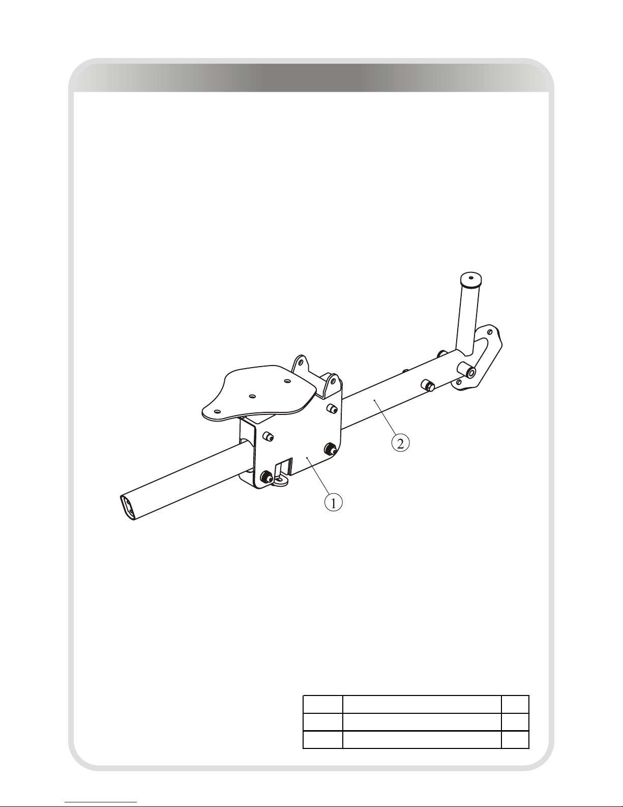
Main Frame II ASSY
Multi Press Exploded View and Parts List
ITEM NO.
Description QTY
1 Main Frame Ⅰ ASSY 1
2 4.5" Pulley 2
3 Pulley Cover 4
4 Socket Head Cap Screw M10*50 2
5 Nylon lock Nut M10 2

─ 25 ─
Main Frame I ASSY
Multi Press Exploded View and Parts List
ITEM NO.
Description QTY
1 Main Frame 1
2 Foot Pad 1

Multi Press Exploded View and Parts List
─ 26 ─
Press Arm ASSY
ITEM NO.
Description QTY
ITEM NO.
Description QTY
1 Press Arm 1 5 Adjustable Plate 1
2 Φ32 End Cap 2 6 Plug RT30*70 2
3 Grip Φ36*Φ28*505 2 7 Socket Set Screw 10-32*3.2 8
4 Φ32 Ring 2 8 Flat Head Cap Screw M5*10 2

Multi Press Exploded View and Parts List
─ 27 ─
Load Arm II ASSY
ITEM NO.
Description QTY
1 Load Arm Ⅰ ASSY 1
2 4.5" Pulley 1
3 Pulley Cover 2
4 Hex Cylinder Head Bolt M10*50 1
5 Nylon lock Nut M10 1

Multi Press Exploded View and Parts List
─ 28 ─
Load Arm I ASSY
ITEM NO.
Description QTY
1 Load Arm 1
2 T type Bearing 2
3 Rubber Bumper Φ45*16.5 1
4 Bushing Φ38*Φ25.4*18 2
5 Spacer Φ25.4*Φ19.3*Φ12.8*18 1
6 Long Pop Pin 1

Multi Press Exploded View and Parts List
─ 29 ─
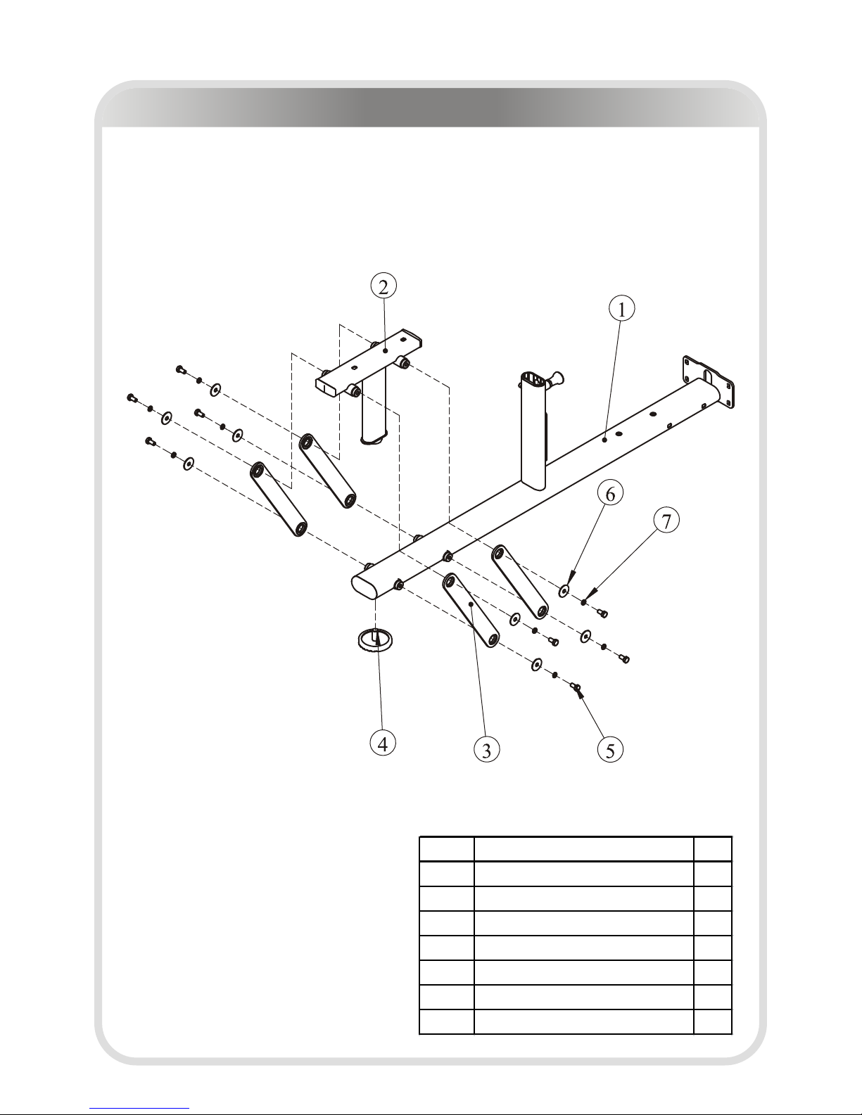
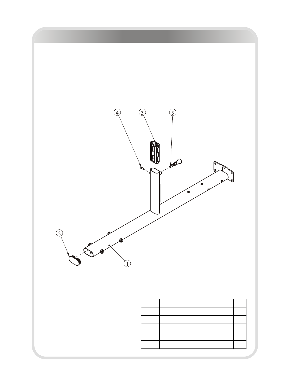
Bace, Main Frame ASSY
ITEM NO.
Description QTY
1 Foot Plate ASSY 1
2 Bace,Main Frame 1
3 Plug 40*80*20 1
4 Foot Pad 1
Foot Plate ASSY
ITEM NO.
Description QTY
1 Foot Plate 1
2 Foot Cover 1
Multi Press Exploded View and Parts List
─ 30 ─
The Guide Frame II ASSY
ITEM NO.
Description QTY
1 Seat Pad Support Ⅱ ASSY 1
2 The Guide Frame Ⅰ ASSY 1

Multi Press Exploded View and Parts List
─ 31 ─
ITEM NO.
Description QTY
1 The Guide Frame 1
2 Hex Head Bolt M10*80 1
3 Plastic Spacer 2
4 Washer Φ20*Φ11*1.5 2
5 Nylon Lock Nut M10 1
6 Bushing Φ25*Φ12.2*13 2
7 Rubber Bumper Φ45*16.5 1
The Guide Frame I ASSY

Multi Press Exploded View and Parts List
─ 32 ─
Seat Pad Support II ASSY
ITEM NO.
Description QTY
ITEM NO.
Description QTY
1 Seat Pad Support Ⅰ ASSY 1 6 Nylon lock Nut M10 1
2
Adjustable Handle Frame Ⅰ ASSY
1 7 Hex Head Bolt M8*65 1
3 Pin Pole 1 8 Flat Washer Φ9*Φ22*1.6 2
4 Nylon lock Nut M8 1 9 Nut M20*18 1
5 Washer Φ20*Φ11*1.5 1 10 Spring 1

Multi Press Exploded View and Parts List
─ 33 ─
Seat Pad Support I ASSY
ITEM NO.
Description QTY
ITEM NO.
Description QTY
1 Seat Pad Support 1 5 Washer Φ20*Φ11*1.5 4
2 Wheel 4 6 Adjustable Spacer 1 4
3 Shoulder Bolt 4 7 Socket Set Screw M6*6 8
4 Adjustable Spacer 2 4 8 Nylon lock Nut M8 4

Multi Press Exploded View and Parts List
─ 34 ─
Frame Back ASSY
ITEM NO.
Description QTY
1 Frame Back 1
2 Plug □25.4*76.2 1
3 Bushing Φ25*Φ12.2*13 4
Adjustable Handle Frame I ASSY
ITEM NO.
Description QTY
1 Adjustable Handle 1
2 Adjustable Handle Grip 1
3 Bushing Φ16*Φ8*8 2

Multi Press Exploded View and Parts List
─ 35 ─
Connector ASSY
ITEM NO.
Description QTY
1 Connector 1
2 4.5" Pulley 1
3 Pulley Cover 2
4 Socket Head Cap Screw M10*50 1
5 Nylon Lock Nut M10 1

Multi Press Exploded View and Parts List
─ 36 ─
Overall
ITEM NO. Description QTY
70 Main Frame Ⅱ ASSY 1
71 Press Arm ASSY 1
72 Load Arm Ⅱ ASSY 1
73 Bace,Main Frame ASSY 1
74 The Guide Frame Ⅱ ASSY 1
78 Frame Back ASSY 1
79 Connector ASSY 1
80 The Back Pad Support 1
84 Cable 4 1
85 Oval Fixed Plate 130 1
86 Axle Φ25.4*130 1
87 AxleΦ25.4*158 1
104 Washer Φ11*Φ38*2 4
105 Flat Washer Φ11*Φ20*2 26
115 Nylon lock Nut M10 9
116 Hex Head Bolt M10*75 4
118 Hex Head Bolt M10*65 4
129 Hex Head Bolt M12*35 2
132 Flat Washer Φ13*Φ24*1.5 14
133 Anchor Shaft M12*140 2
134 Nylon lock Nut M12 9
135 Socket Head Cap Screw M10*20 1
136 Hex Head Bolt M10*25 4
137 Hex Head Bolt M10*30 5
138 Hex Head Bolt M10*45 2
139 Hex Head Bolt M12*125 1
140 Hex Head Bolt M12*120 2
141 Hex Key S=3/16" 1
142 Wrench 1
143 Hex Key S=4 1
144 Hex Key S=5 1
145 Hex Key S=6 1
146 Hex Key S=3 1
147 Hex Key S=8 1
148 Lube 1
151 Shoulder Bolt Φ10*40*M8 1
152 Spacer Φ10.2*Φ14*6 2
153 Cable End 1
154 Nylon Lock Nut M8 1
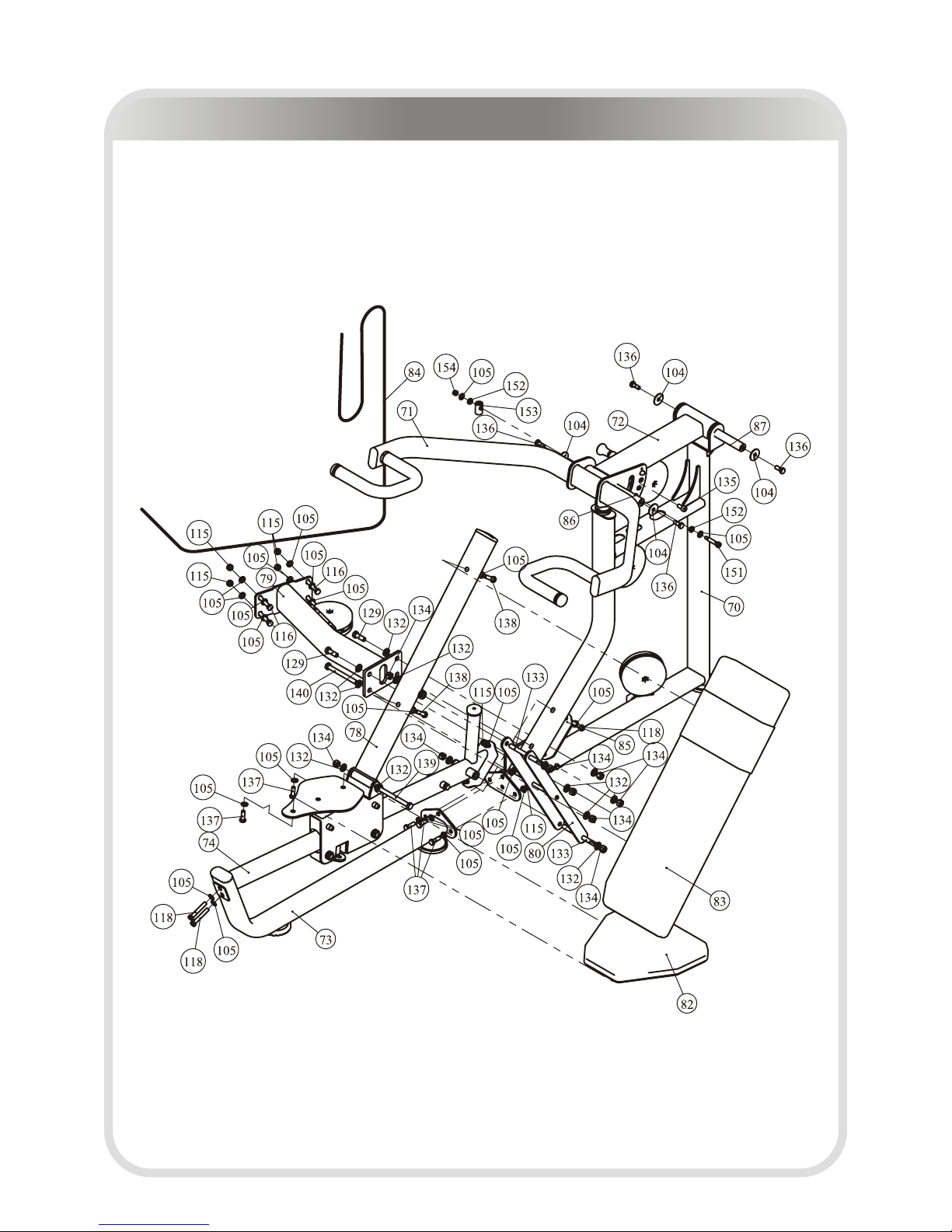
Multi Press Exploded View and Parts List
─ 37 ─
Overall

Multi Press Assembly
─ 38 ─
Attach the Bace, Main Frame ASSY (#73) to the Main Frame II ASSY (#70) using:
● three M10*30 Hex Head Bolt (#137)
● six Φ11*Φ20*2 Flat Washer (#105)
● three M10 Nylon Lock Nut (#115)
Note: Wrench Tighten Bolts and Nylon Lock Nuts.
STEP 1

Multi Press Assembly
─ 39 ─
Attach the Connector ASSY (#79) to the Main Frame II ASSY (#70) using:
● two M12*35 Hex Head Bolt (#129)
● two M12*120 Hex Head Bolt (#140)
● eight Φ13*Φ24*1.5 Flat Washer (#132)
● four M12 Nylon Lock Nut (#134)
Note: Wrench Tighten Bolts and Nylon Lock Nuts.
STEP 2

Multi Press Assembly
─ 40 ─
Attach the Guide Frame II ASSY (#74) to the Main Frame II ASSY (#70) and the Bace,
Main Frame ASSY (#73) using:
● four M10*65 Hex Head Bolt (#118)
● six Φ11*Φ20*2 Flat Washer (#105)
● two M10 Nylon Lock Nut (#115)
● one Oval Fixed Plate 130 (#85)
Note: Wrench Tighten Bolts and Nylon Lock Nuts.
STEP 3

Multi Press Assembly
─ 41 ─
Attach the Frame Back ASSY (#78) and the Back Pad Support (#80) to the Guide
Frame II ASSY (#74) using:
● two M12*140 Anchor Shaft ( #133)
● six Φ13*Φ24*1.5 Flat Washer (#132)
● one M12*125 Hex Head Bolt (#139)
● five M12 Nylon Lock Nut (#134)
Note: Wrench Tighten bolts and Nylon Lock Nuts.
STEP 4
Multi Press Assembly
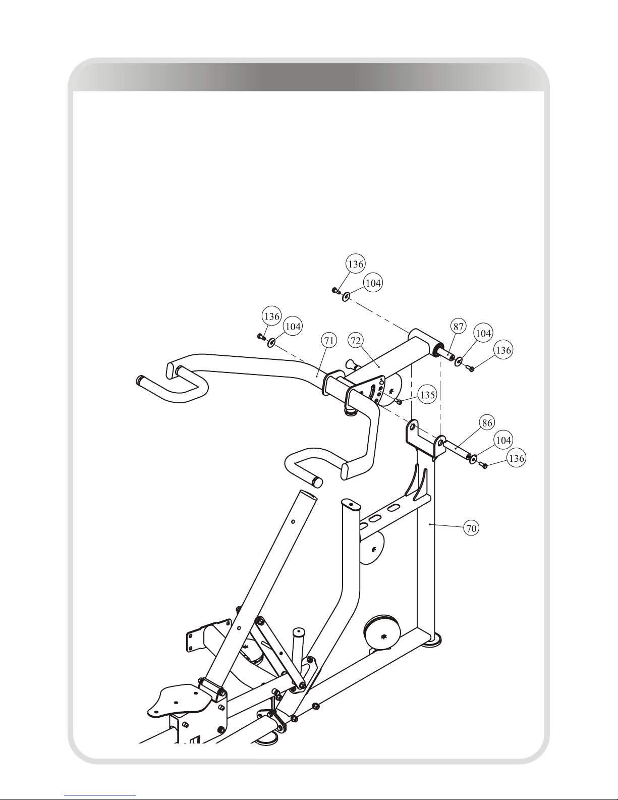
─ 42 ─
Attach the Frame Back ASSY (#71) and the Load Arm II ASSY (#72) to the Main
Frame II ASSY (#70) using:
● four M10*25 Hex Head Bolt (#136)
● four Φ11*Φ38*2 Washer (#104)
● one Φ25.4*130 Axle (#86)
● one Φ25.4*158 Axle (#87)
● one M10*20 Socket Head Cap Screw (#135)
Note: Wrench Tighten bolts and Nylon Lock Nuts.
STEP 5

Multi Press Assembly
─ 43 ─
1. Attach the Back Pad 3 (#83) to the Frame Back ASSY (#78) using:
● two M10*45 Hex Head Bolt (#138)
● two Φ11*Φ20*2 Flat Washer (#105)
2. Attach the Seat Pad 3 (#82) to the Guide Frame II ASSY (#74) using:
● two M10*30 Hex Head Bolt (#137)
● two Φ11*Φ20*2 Flat Washer (#105)
Note: Wrench Tighten bolts and Nylon Lock Nuts.
STEP 6

Multi Press Assembly
─ 44 ─
Attach the Cable (#84) to the Load Arm II ASSY (#72), and go through four 4.5"
Pulley. Using:
● one Φ10*40*M8 Shoulder Bolt (#151)
● two Φ10.2*Φ14*6 Spacer (#152)
● one Φ22*37 Cable End (#153)
● one M8 Nylon Lock Nut (#154)
● two Φ11*Φ20*2 Flat Washer (#105)
Note: Wrench Tighten Bolts and Nylon Lock Nuts.
STEP 7

─ 45 ─
Lat Pulldown / Vertical Row
Lat Pulldown / Vertical Row -------- P45-72
─ 46 ─
Bottom Frame II ASSY
Lat Pulldown / Vertical Row Exploded View and Parts List
ITEM NO.
Description QTY
1 Bottom Frame Ⅰ ASSY 1
2 Seat Frame ASSY 1
3 Plate ASSY 4
4 Foot Plate ASSY 1
5 Hex Head Bolt M10*20 8
6 Flat Washer Φ11*Φ38*2 8
7 Spring Washer Φ10 8
─ 47 ─
Bottom Frame I ASSY
Lat Pulldown / Vertical Row Exploded View and Parts List
ITEM NO.
Description QTY
1 Bottom Frame 1
2 Plug RT50*100 1
3 Plastic Tube Guide 1
4 Socket Head Cap Sc rew M8*20 1
5 Pin 1

─ 48 ─
Seat Frame ASSY
Lat Pulldown / Vertical Row Exploded View and Parts List
ITEM NO.
Description QTY
1 Seat Frame 1
2 Plug □25.4*76.2 2
3 Cushion 1
Plate ASSY
ITEM NO.
Description QTY
1 Plate 1
2 Bushing Φ38*Φ25.4*7.5 2

─ 49 ─
Foot Plate ASSY
Lat Pulldown / Vertical Row Exploded View and Parts List
ITEM NO.
Description QTY
1 Foot Plate 1
2 Foot Cover 1
Vertical Frame I ASSY
ITEM NO.
Description QTY
1 Vertical Frame 1
2 Hook Sheath 2

─ 50 ─
Vertical Frame II ASSY
Lat Pulldown / Vertical Row Exploded View and Parts List
ITEM NO.
Description QTY
1 Vertical Frame Ⅰ ASSY 1
2 2" Pulley 1
3 3.5" Pulley 2
4 Hex Head Bolt M10*50 2
5 Flat Washer Φ11*Φ20*2 4
6 Nylon Lock Nut M10 3
7 3.5" Pulley Cover 2
8 Socket Head Cap Screw M10*50 1

─ 51 ─
Top Frame II ASSY
Lat Pulldown / Vertical Row Exploded View and Parts List
ITEM NO.
Description QTY
ITEM NO.
Description QTY
1 Top Frame Ⅰ ASSY 1 10 Flat Washer Φ11*Φ20*2 24
2 Top Pulley Frame ASSY 2 11 3.5" Pulley 3
3 Small Plate 2 12 4.5" Pulley 5
4 Y Bracket 3 13 V-Type Puley 2
5 L Bracket 3 14 Hex Flanged Nut 1/2"-13 2
6 Hex Head Bolt M10*50 6 15 Screw Shaft 1
7 Hex Head Bolt M10*65 4 16 Welded plate 1
8 Hex Head Bolt M10*45 2 17 Retainning Stap Ring 2
9 Nylon Lock Nut M10 12

─ 52 ─
Top Frame I ASSY
Lat Pulldown / Vertical Row Exploded View and Parts List
ITEM NO.
Description QTY
1 Top Frame 1
2 Plug □40*80 2
3 Hole Clip 4
4 Bearing 6006-2Z 4
5 Nut M8 2

─ 53 ─
Top Pulley Frame ASSY
Lat Pulldown / Vertical Row Exploded View and Parts List
Back Frame ASSY
ITEM NO.
Description QTY
1 Top Pulley Frame 1
2 Hook Sheath 2
ITEM NO.
Description QTY
1 Back Frame 1
2 Foot Pad 1
3 Plug □50*100 1

─ 54 ─
Middle Frame II ASSY
Lat Pulldown / Vertical Row Exploded View and Parts List
ITEM NO.
Description QTY
1 Middle Frame Ⅰ ASSY 1
2 4.5" Pulley 2
3 3.5" Pulley 4
4 Nylon Lock Nut M10 5
5 Flat Washer Φ11*Φ20*2 11
6 Hex Head Bolt M10*50 6

─ 55 ─
Middle Frame I ASSY
Lat Pulldown / Vertical Row Exploded View and Parts List
ITEM NO.
Description QTY
1 Middle Frame 1
2 Plug □50.8 7
3 Nut M8 6
4 Foot Pad 6

─ 56 ─
Tube Frame ASSY
Lat Pulldown / Vertical Row Exploded View and Parts List
Small Top Frame ASSY
ITEM NO.
Description QTY
1 Tube Frame 1
2 Bronze Bushing Φ38 1
ITEM NO.
Description QTY
1 Small Top Frame 1
2 Plug □50.8 2
3 Nut M8 2

─ 57 ─
Double Pulley Assy
Lat Pulldown / Vertical Row Exploded View and Parts List
ITEM NO.
Description QTY
1 Double Pulley 1
2 3.5" Pulley 2
3 Hex Head Bolt M10*50 2
4 Flat Washer Φ11*Φ20*2 4
5 Nylon Lock Nut M10 2
Pulley Bracket ASSY
ITEM NO.
Description QTY
1 Pulley Bracket 1
2 3.5" Pulley 1
3 Hex Head Bolt M10*50 1
4 Flat Washer Φ11*Φ20*2 2
5 Nylon Lock Nut M10 1

─ 58 ─
FOAM Frame ASSY
Lat Pulldown / Vertical Row Exploded View and Parts List
ITEM NO.
Description QTY
1 FOAM Frame 1
2 Nut 2
Pulley Bracket W/Shaft ASSY
ITEM NO.
Description QTY
1 Pulley Bracket W/Shaft 1
2 3.5" Pulley 1
3 Hex Flanged Nut 1/2"-13 2
4 Hex Head Bolt M10*50 1
5 Flat Washer Φ11*Φ20*2 2
6 Nylon Lock Nut M10 1

─ 59 ─
Foot Tube ASSY
Lat Pulldown / Vertical Row Exploded View and Parts List
ITEM NO.
Description QTY
1 Foot Tube 1
2 Foot Sleeve 2

─ 60 ─
Lat Pulldown / Vertical Row Exploded View and Parts List
Overall
ITEM NO.
Description QTY
ITEM NO.
Description QTY
1 Bottom Frame Ⅱ ASSY 1 50 Back Pad 2 1
2 Vertical Frame Ⅱ ASSY 1 82 Seat Pad 3 1
3 Connection Frame 1 83 Back Pad 3 1
4 R24 Fixed Plate 1 101 Gear Hook 3
5 Top Frame Ⅱ ASSY 1 102 Selector Pin W/Coil 3
6 Back Frame ASSY 1 103 Weight Rubber Bumper 6
7 Middle Frame Ⅱ ASSY 1 104 Washer Φ11*Φ38*2 2
8 Fixed Plate 130 1 105 Flat Washer Φ11*Φ20*2 47
9 Long Lat Bar 1 106 Button Head Cap Screw M10*30 2
10 Row Handle 1 107 Washer Φ5.5*Φ10*1 8
11 Tube Frame ASSY 1 108 Screw M5*12 4
12 Small Top Frame ASSY 2 109 Nylon Lock Nut M5 4
13 Chain 1 110 Nylon Spacer 2
14 Cup Holder 2 111 Washer Φ9*Φ16*1.6 6
15 Guide Rod Φ25*2.5*1863 2 112 Spring Washer Φ8 12
16 FOAM 6 113 Hex Head Bolt M8*20 6
17 Guide Rod Φ25*2.5*1695 4 114 Socket Set Screw M8*8 12
18 Seat Pad 1 1 115 Nylon Lock Nut M10 19
20 L Plate 3 116 Hex Head Bolt M10*75 10
21 Shaft 6 117 Hex Head Bolt M10*80 4
24 Double Pulley ASSY 1 118 Hex Head Bolt M10*65 2
25 Pulley Bracket ASSY 1 119 Hex Head Bolt M10*50 2
28 FOAM Frame ASSY 1 120 Hex Head Bolt M10*20 4
30 Iron Shroud 3 121 Hex Head Bolt M10*60 2
31 Top Shroud Plate 2 122 Hex Head Bolt M10*105 2
32 Pulley Bracket W/Shaft ASSY 1 123 Mount Sleeve 6
37 Cable 1 1 124 Flat Washer Φ9*Φ22*1.6 16
38 Cable 2 1 125 Button Head Cap Screw M8*25 2
39 Foot Tube ASSY 1 126 Button Head Cap Screw M8*15 14
40 R20 Fixed Plate 1 127 Plastic Washer Φ60*Φ25.7*3 4
49 Seat Pad 2 1

─ 61 ─
Lat Pulldown / Vertical Row Exploded View and Parts List
Overall

Lat Pulldown / Vertical Row Assembly
─ 62 ─
1. Attach the Bottom Frame II ASSY (#1) to the Middle Frame II ASSY (#7) using:
● four M10*75 Hex Head Bolt (#116)
● eight Φ11*Φ20*2 Flat Washer (#105)
● four M10 Nylon Lock Nut (#115)
2. Attach the Back Frame ASSY (#6) to the Middle Frame II ASSY (#7) using:
● two M10*80 Hex Head Bolt (#117)
● three Φ11*Φ20*2 Flat Washer (#105)
● one M10 Nylon Lock Nut (#115)
Note: Wrench Tighten Bolts and Nylon Lock Nuts.
STEP 1
Lat Pulldown / Vertical Row Assembly
─ 63 ─
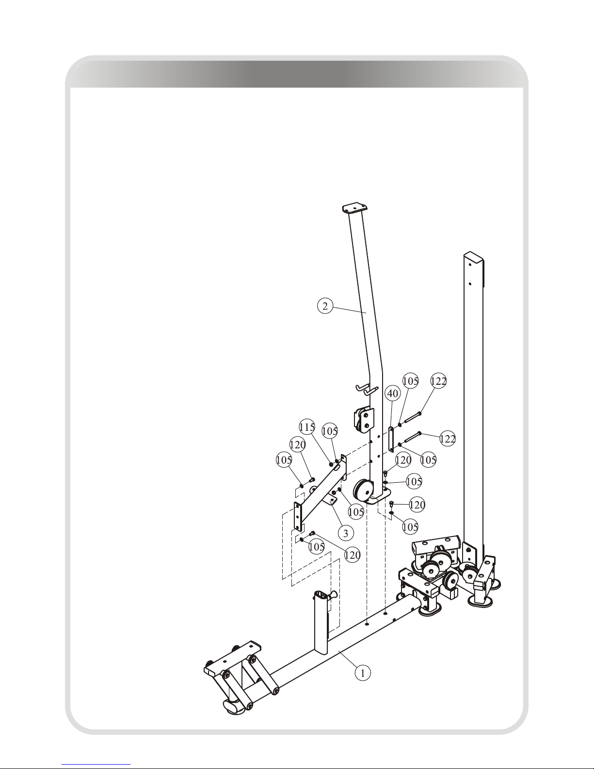
1. Attach the Vertical Frame II ASSY (#2) to the Bottom Frame II ASSY (#1) using:
● two M10*20 Hex Head Bolt (#120)
● two Φ11*Φ20*2 Flat Washer (#105)
2. Attach the Connection Frame (#3) to the Bottom Frame II ASSY (#1) & the Vertical
Frame II ASSY (#2) using:
● two M10*20 Hex Head Bolt (#120)
● two M10*105 Hex Head Bolt (#122)
● one R20 Fixed Plate (#40)
● six Φ11*Φ20*2 Flat Washer (#105)
● two M10 Nylon Lock Nut (#115)
Note: Hand tighten bolts and Nylon Lock nuts.
STEP 2

Lat Pulldown / Vertical Row Assembly
─ 64 ─
Attach the Top Frame II ASSY (#5) to the Vertical Frame II ASSY (#2) & Back Frame
ASSY (#6) using:
● two M10*65 Hex Head Bolt (#118)
● two M10*80 Hex Head Bolt (#117)
● one Fixed Plate 130 (#8)
● eight Φ11*Φ20*2 Flat Washer (#105)
● four M10 Nylon Lock Nut (#115)
Note: Wrench Tighten Bolts and Nylon Lock Nuts.
STEP 3

Lat Pulldown / Vertical Row Assembly
─ 65 ─
1. Attach two Small Top Frame ASSY (#12) to the Top Frame II ASSY (#5) using:
● four M10*75 Hex Head Bolt (#116)
● eight Φ11*Φ20*2 Flat Washer (#105)
● four M10 Nylon Lock Nut (#115)
2. Attach the Tube Frame ASSY (#11) to the Vertical Frame II ASSY (#2) using:
● two M10*60 Hex Head Bolt (#121)
● four Φ11*Φ20*2 Flat Washer (#105)
● two M10 Nylon Lock Nut (#115)
3. Attach the Foot Tube ASSY (#39) to the Connection Frame (#3) using:
● two M10*75 Hex Head Bolt (#116)
● one R24 Fixed Plate (#4)
● four Φ11*Φ20*2 Flat Washer (#105)
● two M10 Nylon Lock Nut (#115)
4. Attach the FOAM Frame ASSY (#28) to the Bottom Frame II ASSY (#1).
Note: Wrench Tighten bolts and Nylon Lock Nuts.
1. Attach:
● four Φ25*2.5*1695 Guide Rods (#17)
● two Φ25*2.5*1863 Guide Rods (#15)
● six Weight Rubber Bumper (#103)
● fifty seven Weight Plate 10LBS (#19)
● three Top Plate (#29)
to the Middle Frame II ASSY (#7) & the Top Frame II ASSY (#5) using:
● six Mount Sleeve (#123)
● twelve M8*8 Socket Set Screw (#114)
2. Attach the three Selector Pin W/Coil (#102) to the three Top Plate (#29).
Note: Wrench Tighten bolts and Nylon Lock nuts.
STEP 4
STEP 5

Lat Pulldown / Vertical Row Assembly
─ 66 ─
STEP 4

Lat Pulldown / Vertical Row Assembly
─ 67 ─
STEP 5

Lat Pulldown / Vertical Row Assembly
─ 68 ─
1. Attach the two Foam (#16) to the FOAM Frame ASSY (#28) using:
● four Φ60*Φ25.7*3 Plastic Washer (#127)
● two Φ11*Φ38*2 Washer (#104)
● two M10*30 Button Head Cap Screw (#106)
● two Φ11*Φ20*2 Flat Washer (#105)
2. Attach the Seat Pad 1(#18) to the Bottom Frame II ASSY (#1) using:
● two M10*50 Hex Head Bolt (#119)
● two Φ11*Φ20*2 Flat Washer (#105)
Note: Wrench Tighten bolts and Nylon Lock Nuts.
STEP 6
Lat Pulldown / Vertical Row Assembly
─ 69 ─
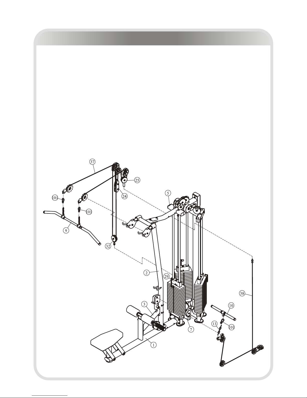
1. Attach the Cable 1 (#37) to the Top Frame II ASSY (#5) & the Top Plate (#29) using:
● one Double Pulley ASSY (#24)
● one Pulley Bracket ASSY (#25)
● one Pulley Bracket W/Shaft ASSY (#32)
2. Attach Long Lat Bar (#9) to the Cable 1 (#37) using:
● two Gear Hook (#101)
3. Attach the Cable 2 (#38) to Pulley Bracket ASSY (#25) & the Middle Frame II ASSY
(#7) & the Vertical Frame II ASSY (#2).
4. Attach Row Handle (#10) to the Cable 2 (#38) using:
● one Gear Hook (#101)
● one Chain (#13)
Note: Wrench Tighten bolts and Nylon Lock Nuts.
STEP 7

Assembly
─ 70 ─
1. Attach the LEG EXT/LEGCUR & MULTI PRESS to the Middle Frame II ASSY (#7)
using:
● eight M10*75 Hex Head Bolt (#116)
● sixteen Φ11*Φ20*2 Flat Washer (#105)
● eight M10 Nylon Lock Nut (#115)
2. Attach the Cable 3 (#51) & Cable 4 (#84) to the Top Frame II ASSY (#5) & the Top
Plate (#29).
Note: Wrench Tighten bolts and Nylon Lock Nuts.
STEP 8
1. Attach two Cup Holder (#14) to the two Iron shroud (#30) using:
● four M5*12 Screw (#108)
● eight Φ5.5*Φ10*1 Washer (#107)
● four M5 Nylon Lock Nut (#109)
2. Attach six Shaft (#21) to the Middle Frame II ASSY (#7) using:
● six Φ8 Spring Washer (#112)
3. Attach three L Plate (#20) to the Top Frame II ASSY (#5) & two Small Top Frame
ASSY (#12) using:
● six M8*20 Hex Head Bolt (#113)
● six Φ8 Spring Washer (#112)
● six Φ9*Φ16*1.6 Washer (#111)
4. Attach three Iron shroud (#30) to the Middle Frame II ASSY (#7) & three L Plate
(#20) using:
● twelve M8*15 Button Head Cap Screw (#126)
● twelve Φ9*Φ22*1.6 Flat Washer (#124)
5. Attach two Top Shroud Plate (#31) to the Top Frame II ASSY (#5) using:
● two M8*15 Button Head Cap Screw (#126)
● two M8*25 Button Head Cap Screw (#125)
● two Nylon Spacer (#110)
● four Φ9*Φ22*1.6 Flat Washer (#124)
Note: Wrench Tighten bolts and Nylon Lock Nuts.
STEP 9

Assembly
─ 71 ─
STEP 8

Assembly
─ 72 ─
STEP 9

─ 73 ─
Maintenance Schedule
Your equipment comes with a commercial maintenance decal. For personal,
in home use, please follow the home maintenance schedule listed above.
ROUTINE
COMMERCIAL
MAINTENANCE
HOME
MAINTENANCE
Inspect;
Links, Pull Pins, Snap Locks,
Swivels, Weight Stack Pins
DAILY WEEKLY
Clean;
Upholstery
DAILY WEEKLY
Inspect;
Cables or Belts and their tension
DAILY WEEKLY
Inspect;
Accessory Bars, and Handles
WEEKLY 3 MONTHS
Inspect;
All Decals
WEEKLY 3 MONTHS
Inspect;
All Nuts and Bolts, Tighten if
needed
WEEKLY 3 MONTHS
Inspect;
Anti-Skid Surface
WEEKLY 3 MONTHS
Clean & Lubricate;
Guide Rods with a Teflon (PTFE)
based lubricant (Superlube)
MONTHLY 3 MONTHS
Lubricate;
Seat Sleeves, Turcite Bushings,
Linear Bearing
MONTHLY 3 MONTHS
Clean and Wax;
All Glossy Finishes
6 MONTHS YEARLY
Repack with Grease;
Linear Bearings
6 MONTHS YEARLY
Replace;
Cables, Belts and Connecting
Parts
YEARLY 3 YEARS
LATEST DATE ENTRY

─ 74 ─
General Maintenance Information
PLEASE KEEP THIS FOR YOUR RECORDS
Links, Pull-Pins , Snap Hooks , Swiv els, W eigh t Stac k Pins :
* Check all pieces for signs of visible wear or damage.
* Check springs in snap hooks and pull-pins for proper tension and alignment.
* If the spring sticks or has lost its rigidity, replace it immediately.
Uphols tery :
* To ensure prolonged upholstery life and proper hygiene, all upholstered pads should be wiped
down with a damp cloth after every workout.
* Periodically take the time to use a mild soap or an approved vinyl upholster y cleaner to deter
the onset of cracking or drying. Avoid using any abrasive cleaners or cleaners not intended for
use on vinyl.
* Replace ripped or warn upholstery immediately.
* Keep sharp or pointed objects clear of all upholster y.
Decals:
* Inspect and familiarize yourself with any safety warnings or other user information posted on
each decal.
Nuts and Bolts :
* Inspect all nuts and bolts for any loosening and tighten if needed.
* Go through a re-tightening sequence periodically to ensure that all hardware is tensioned
proper.
Anti-Skid Su rfac es:
* These surfaces are designed to supply secure footing and need to be replaced if they appear
worn or become slippery.
Belts an d Cabl es:
* We uses only high quality belt, and mil-spec cables.
* Visually inspect the belts and cables for fraying, cracking, peeling or discoloration.
* While the machine is not in use, carefully run your fingers along the belt or cable to feel for
thinning or bulging areas.
* Replace belts and cables immediately at the first signs of damage or wear. Do not use
equipment until belts or cables have been replaced.
Belt and C able T ensi on:
* Referring to the Owners Manual, when belts or cables are used check all bolts attachments to
be sure they are properly attached.
* Check slack in cables and re-adjust cable tension if needed.
Se at Sle eves , Guid e Rods :
* Wipe down adjusting tubes with a dust free rag before applying lubricant.
* Lubricate seat sleeves and Guide Rods with a Silicon or Teflon based lubricant spray.
Linear Beari ngs:
* Referring to the Owners Manual carefully disassemble the bearing from its housing and place
a finger full of light grease (lithium, super lube, etc.) into the inside of the bearing. Using your
finger, press the grease into the ball-bearings and their tracks. repeat until the ball-bearing
tracks are full of grease. Inser t the shaft back into the bearing and wipe off excess grease.

─ 75 ─
Weight Training Tips
Use thi s manual to guide you through the basic exercise s yo u can perfo rm on
yo ur equipment. To gain maximum results and avoid poss ible injur y, co nsult a
fit ness professional to develop your complete exercise program.
Always consult your physician before starting any exercise program.
To be successful in your exercise program, it is important to develop an
understanding of the basic principles of strength training. Now that you have
your equipment, it is only natural that you want to get started immediately.
First, determine a set of realistic goals and objectives for yourself. By deciding on
an exercise plan that is right for you prior to starting, you will contribute
significantly to your success.
Warm up p roperly before engag i n g i n we ight resistance trainin g. Stretching,
yoga , jo g ging, calis t h enics or other cardio vascular exe rcise can help prepar e
your b o dy for the heavie r work load of lifting weights.
Learn how to per form the exercise correctly before using heavy weight. Correct
form is important to avoid injury and to ensure that you work the proper muscle
groups.
Know your limitations. If you are new to weight training or are embarking on an
exercise regimen after a long layoff, start slowly and build foundational strength
over a longer period of time.
Pay attention to your breathing. Exhale when you exert is a general rule of thumb.
Never hold your breath.
Specifications
Class: S
Maximum Wt. Capacity: 3*91Kg/ 3*200lbs.
Maximum User Weight: 135Kg/ 300lbs.

 Loading...