

Page 1
DSCA45
Frequency Input Signal Conditioners
Description
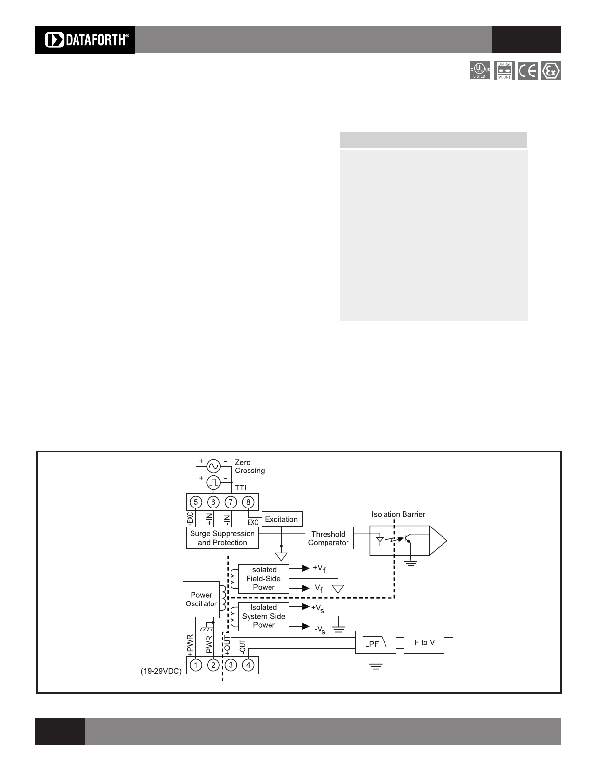
Each DSCA45 frequency input module provides a single channel of frequency
input which is isolated and converted to a standard analog voltage or current
output (Figure 1).
The frequency input signal can be a TTL level or zero-crossing signal. Terminal
7 (-IN) on the field-side terminal block is the common or ground connection
for input signals. A TTL signal is connected from terminal 6 (+IN) to terminal 7
(-IN), while a zero-crossing signal is connected from terminal 5 (+EXC) to
terminal 7 (-IN). Input circuitry for each of the signal types has hysteresis built
in. An input signal must cross entirely through the hysteresis region in order to
trigger the threshold comparator.
A +5.1V excitation is available for use with magnetic pick-up or contact-closure
type sensors. The excitation is available on terminal 8 (-EXC) with return at
terminal 7 (-IN).
Module output is either voltage or current. For current output models a dedicated
loop supply is provided at terminal 3 (+OUT) with loop return located at terminal
4 (-OUT). The system-side load may be either floating or grounded.
High Performance Signal Conditioners
▲
Features
Accepts Frequency Inputs of 0 to 100kHz
Industry Standard Output of Either 0-10V,
0-20mA, or 4-20mA
±0.05% Factory Calibrated Accuracy
Adjustable Zero (±5%) and Span (±5%)
1500Vrms Transformer Isolation
Input Overload Protected to 240VAC
Continuous
ANSI/IEEE C37.90.1 Transient Protection
Mounts on Standard DIN Rail
C-UL-US Listed
CE and ATEX Compliant
DSCA
Special input circuits provide protection against accidental connection of power-
line voltages up to 480VAC and against transient events as defined by ANSI/
IEEE C37.90.1. Protection circuits are also present on the signal output and
power input terminals to guard against transient events and power reversal.
Signal and power lines are secured to the module using screw terminals which
are pluggable terminal blocks for ease of system assembly and reconfiguration.
DSCA45 modules have excellent stability over time and do not require
recalibration, however, both zero and span settings are adjustable to accom-
modate situations where fine tuning is desired. The adjustments are made using
potentiometers located under the front panel label and are non-interactive for
ease of use.
Figure 1: DSCA45 Block Diagram
152
For information call 800-444-7644
Page 2

High Performance Signal Conditioners
DSCA
Specifications
Module
Input
Range 0 to 100kHz max
Threshold Zero Crossing
Minimum Input 60mVp-p
Maximum Input 350Vp-p
Minimum Pulse Width 4µs
TTL Input Low 0.8V max
TTL Input High 2.4V min
Hysteresis
Zero Crossing 40mV
TTL 1.5V
Resistance 100kΩ
Protection
Continuous 240Vrms max
Transient ANSI/IEEE C37.90.1
Output Range See Ordering Information
Adjustability ±5% Zero & Span
Load Resistance (I
Current Limit 8mA (V
Output Protection
Short to Ground Continuous
Transient ANSI/IEEE C37.90.1
Ripple <0.20% Span at input >2% Span
Accuracy
vs. Temperature ±40ppm/°C (Zero & Span)
Nonlinearity ±0.02% Span
Isolation (Common Mode)
Input to Output, Input to Power
Continuous 1500Vrms max
Transient ANSI/IEEE C37.90.1
Output to Power
Continuous 50VDC max
Rejection (50-60Hz Common Mode) 120dB
Response Time (0 to 90%)
DSCA45-01, -02, -03 310ms, 175ms, 50ms
DSCA45-04, -05, -06 30ms, 30ms, 15ms
DSCA45-07, -08 15ms, 1.5ms
Field Excitation +5.1V ±5% at 8mA max
Power Supply
Voltage 19 to 29VDC
Current 60mA (V
Sensitivity ±0.0002%/%
Protection
Reverse Polarity Continuous
Transient ANSI/IEEE C37.90.1
Environmental
Operating & Storage Temp. Range -40°C to +80°C
Emissions EN61000-6-4 ISM, Group 1
Immunity EN61000-6-2 ISM, Group 1
Mechanical Dimensions 2.95" x 0.89" x 4.13"
Mounting DIN EN50022-35x7.5
NOTES:
(1) Includes nonlinearity, hysteresis and repeatability.
(1)
ATEX Group II, Category 3 -20°C to +40°C
Relative Humidity 0 to 95% noncondensing
Radiated, Conducted Class A
R F Performance A ±0.05% Span Error
ESD, EFT, Surge, Voltage Dips Performance B
(h)(w)(d) (75mm x 22.5mm x 105mm)
Typical at TA=+25°C and +24V supply voltage
DSCA45
) 600Ω max.
OUT
OUT
±0.05% Span
OUT
or -35x15 rail
), 30mA (I
), 80mA (I
OUT
OUT
Ordering Information
Model Input Range Output Range
DSCA45-01 0-500Hz 2, 3, 4
DSCA45-02 0-1kHz 2, 3, 4
DSCA45-03 0-2.5kHz 2, 3, 4
DSCA45-04 0-5kHz 2, 3, 4
DSCA45-05 0-10kHz 2, 3, 4
DSCA45-06 0-25kHz 2, 3, 4
DSCA45-07 0-50kHz 2, 3, 4
DSCA45-08 0-100kHz 2, 3, 4
Output Ranges Available
Output Range Part No. Suffix Example
1. -10V to +10V NONE N/A
)
2. 0V to +10V NONE DSCA45-01
3. 4 to 20mA C DSCA45-01C
4. 0 to 20mA E DSCA45-01E
DSCA
)
Installation Notes:
1.) This Equipment is Suitable for Use in Class I, Division 2, Groups A, B, C, D, or Non-Hazardous Locations Only.
2.) Warning - Explosion Hazard - Substitution of Components May Impair Suitability for Class I, Division 2.
3.) Warning - Explosion Hazard - Do Not Disconnect Equipment Unless Power Has Been Switched Off or The
Area is Known to be Non-Hazardous.
Visit our website www.dataforth.com
153
 Loading...