

Page 1
READ AND SAVE THESE INSTRUCTIONS
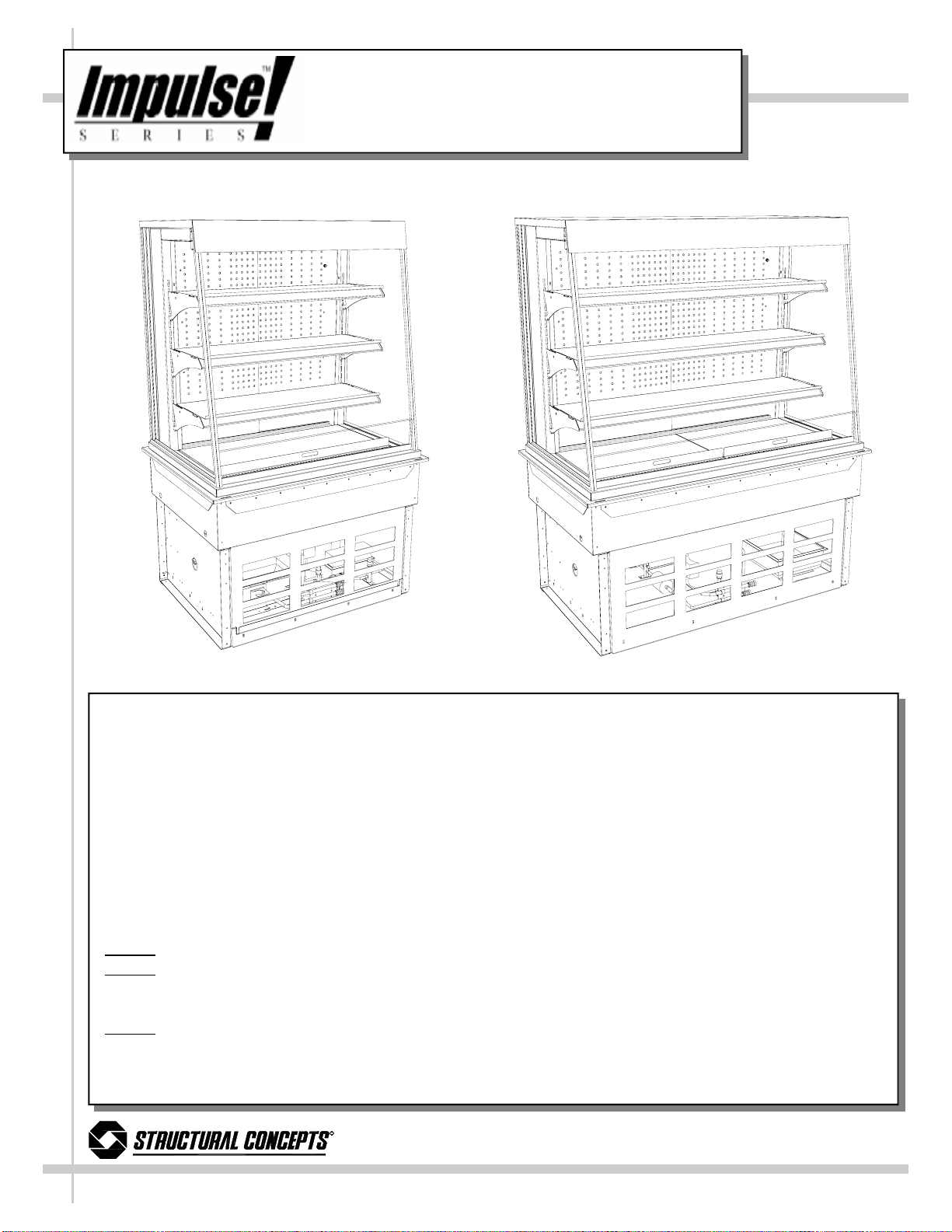
INSTALLATION &
OPEN REFRIGERATED SELF-SERVICE MERCHANDISER
SERVICE DROP-IN REFRIGERATED MERCHANDISER
OPERATING MANUAL
PN 99574
Model DO3637R
Model DO3637R 38 1/8”L x 28 5/8”D x 37 1/4”H (Upper Display Case Only)
Model DO4837R
38 1/8”L x 28 5/8”D x 61 1/8”H (Upper Display Case + Drop-In Refrigeration Unit)
Model DO4837R 50 1/8”L x 28 5/8”D x 37 1/4”H (
Model DO3623R 38 1/8”L x 28 5/8”D x 23 1/4”H (Upper Display Case Only)
50 1/8”L x 28 5/8”D x 61 1/8”H (Upper Display Case + Drop-In Refrigeration Unit)
Upper Display Case Only)
38 1/8”L x 28 5/8”D x 47 1/8”H (Upper Display Case + Drop-In Refrigeration Unit)
Model DO4823R 50 1/8”L x 28 5/8”D x 23 1/4”H (Upper Display Case Only)
50 1/8”L x 28 5/8”D x 47 1/8”H (Upper Display Case + Drop-In Refrigeration Unit)
Note 1. Internal counter height must be at least 28” for refrigeration and proper air flow space.
Note 2
(with a minimum 1.42” perimeter) for proper clearance and fit of Drop-In Refrigerated Merchandiser.
These combined dimensions require a 30” minimum counter top space for cutout.
Note 3
Long (with a minimum 1.42” perimeter) for proper clearance and fit of Drop-In Refrigerated
Merchandiser. These combined dimensions require a 30” minimum counter top space for cutout.
. Model DO3637R & 3623R: Service Top Cutout dimensions must be 27.15” Wide x 36.65” Long
. Model DO4837R & DO23R: Service Top Cutout dimensions must be 27.15” Wide x 48.65”
R
888 Porter Rd. Muskegon, MI 49441 Phone: 231.798.8888 Fax: 231.798.4960 www.structuralconcepts.com
L:\Inst & Oper Man\Oasis\DO(L)37R, DO(L)23R Operr Man 99574.pub
Rev F Date: 11.2.2006
Page 2
TABLE OF CONTENTS
OVERVIEW AND WARNINGS ...………………………..…………………..…….………….....…..
CUSTOMER CABINET PROVISIONS…………………..…………………..…….………….....…..
CLEARANCE AND AIR FLOW ...………………………..…………………..…….………….....…..
VENTING INSTRUCTIONS FOR AIR INTAKE / EXHAUST - DO3637R ……………………..
VENTING INSTRUCTIONS FOR AIR INTAKE / EXHAUST - DO4837R ……………………..
VENTING INSTRUCTIONS FOR AIR INTAKE / EXHAUST - DO3623R ……………………..
INSTALLATION …………………………………………………………… …………………………..
START-UP AND OPERATION ..…………………………………………………………………….
MAINTENANCE FUNDAMENTALS ..……………………………………………………………….
REFRIGERATION FUNDAMENTALS ……………….………………………………………..…...
REFRIGERATION SLIDE-OUT EXPLODED PICTORIAL ……………………………………….
TECHNICAL INFORMATION SHEET - MODEL DO3637R ..……………………………..….…
TECHNICAL INFORMATION SHEET - MODEL DO4837R ..……………………………..….…
TECHNICAL INFORMATION SHEET - MODEL DO3623R ..……………………………..….…
TECHNICAL INFORMATION SHEET - MODEL DO4823R ..……………………………..….…
TROUBLESHOOTING ..………………….……………………………………………….………….
CLEANING SCHEDULE ....…………………………………………………...………………….….
CPC® ESC3 CONTROLLER OVERVIEW …………………………………………………………
CPC® ESC3 CONTROLLER OPERATION ……………………………………………………….
CPC® ESC3 SET POINT CHANGING INSTRUCTIONS ….………………………………… …
WARRANTY ……………...…………………...………………………………..……… ……………..
TECHNICAL SERVICE ..……………………………...……………………………………….…..…
3
4
5
6
7
8
9
10
11-13
14
15
16
17
18
19
20-21
22
23
24
25
26
27
R
888 Porter Rd. Muskegon, MI 49441 Phone: 231.798.8888 Fax: 231.798.4960 www.structuralconcepts.com
2
Page 3
OVERVIEW AND WARNINGS
OVERVIEW
• The Structural Concepts® Oasis® refrigerated self-service cases are designed to
merchandise packaged products at 5° Celsius / 41° Fahrenheit or less product temperatures.
• These cases should be installed and operated according to the following instructions to insure
proper performance.
• This unit is designed for the display of products in ambient store conditions where
temperatures and humidity are maintained at a maximum of 24°C / 75°F and 55% relative
humidity.
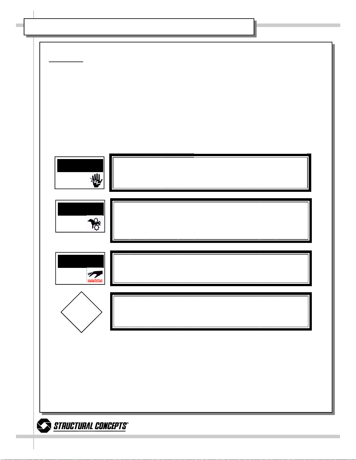
WARNING
ELECTRICAL
HAZARD
WARNING
KEEP HANDS
CLEAR
WARNING
HOT
SURFACE
CAUTION
WARNING
Risk of Electric Shock.
Disconnect Power Before Servicing Unit
WARNING
Hazardous Moving Parts.
Do Not Operate unit with covers removed.
Fan blades may be exposed when deck panel is removed. Disconnect
power before removing deck panel.
WARNING
Evaporator Tray is Hot
CAUTION
Lamps have been treated to resist breakage and must be replaced with a
similarly treated lamp.
R
888 Porter Rd. Muskegon, MI 49441 Phone: 231.798.8888 Fax: 231.798.4960 www.structuralconcepts.com
3
Page 4
CUSTOMER CABINET PROVISIONS
Customer Cabinet Provisions
• Customer provided cabinet must adhere to the minimum requirements in ANSI/UL Std. 471 and
ANSI/NSF Std. 7.
• Among the factors that are to be taken into consideration when judging the acceptability of a
cabinet or similar enclosure are mechanical strength, resistance to impact, moisture-absorptive
properties, flame resistance, resistance to distortion at temperatures to which the material may
be subjected under conditions of use, and resistance to corrosion.
• Customer provided cabinet or similar enclosure shall have the strength and rigidity necessary to
resist conditions of intended use without increasing the risk of fire or injury to persons due to total
or partial collapse. Cabinet or similar enclosure must be strong enough to hold weight of cabinet
and intended product load. Dry weight (no product in case) exceeds 500 pounds.
• A nonmetallic cabinet or similar enclosure (or part of an enclosure) shall have a flame spread
index of not more than 200 when tested in accordance with the Standard for Tests for Surface
Burning Characteristics of Building Materials, UL 723.
• The cabinet or similar enclosure shall be constructed and assembled to reduce the risk of fire
due to the emission of molten metal, burning insulation, flaming particles, or the like, through
openings onto flammable material, including the surface over which the refrigeration is mounted.
• A sheet metal cabinet or similar enclosure is to be judged for acceptability with respect to its
size, shape, metal thickness. Sheet metal such as galvanized or stainless shall be 0.30 inch (22
gage) or greater.
• Steel enclosures shall be protected against corrosion by metallic or nonmetallic coatings, such
as plating or painting.
• The refrigeration access panel/door shall be arranged so that main power switch, refrigeration
controller and refrigeration package are accessible without removing parts other than access
panel/door.
• A hinged or pivoted panel shall be positioned or arranged so that when it is in an open position
falling or swinging due to gravity or vibration will not cause injury to persons.
• For electrical protection when installed in its intended manner, louvers and other openings in the
enclosure shall be constructed and located to reduce the risk of unintentional contact with moving, live or hot parts such as fan blades and condensate trays. The minor dimension of such
openings shall not exceed 3 inches—See Table 6.1 for Clearance from Openings. Tools are required to remove covers, panels or grilles unless interlock is provided.
• Ventilation openings/louvers shall be free of sharp edges and burrs and have spaces large
enough to allow for easy cleaning. Louvers that may be subject to splashes, spills, and overhead
drips shall be of a drip-deflecting design.
R
888 Porter Rd. Muskegon, MI 49441 Phone: 231.798.8888 Fax: 231.798.4960 www.structuralconcepts.com
4
Page 5

CLEARANCE AND AIR FLOW
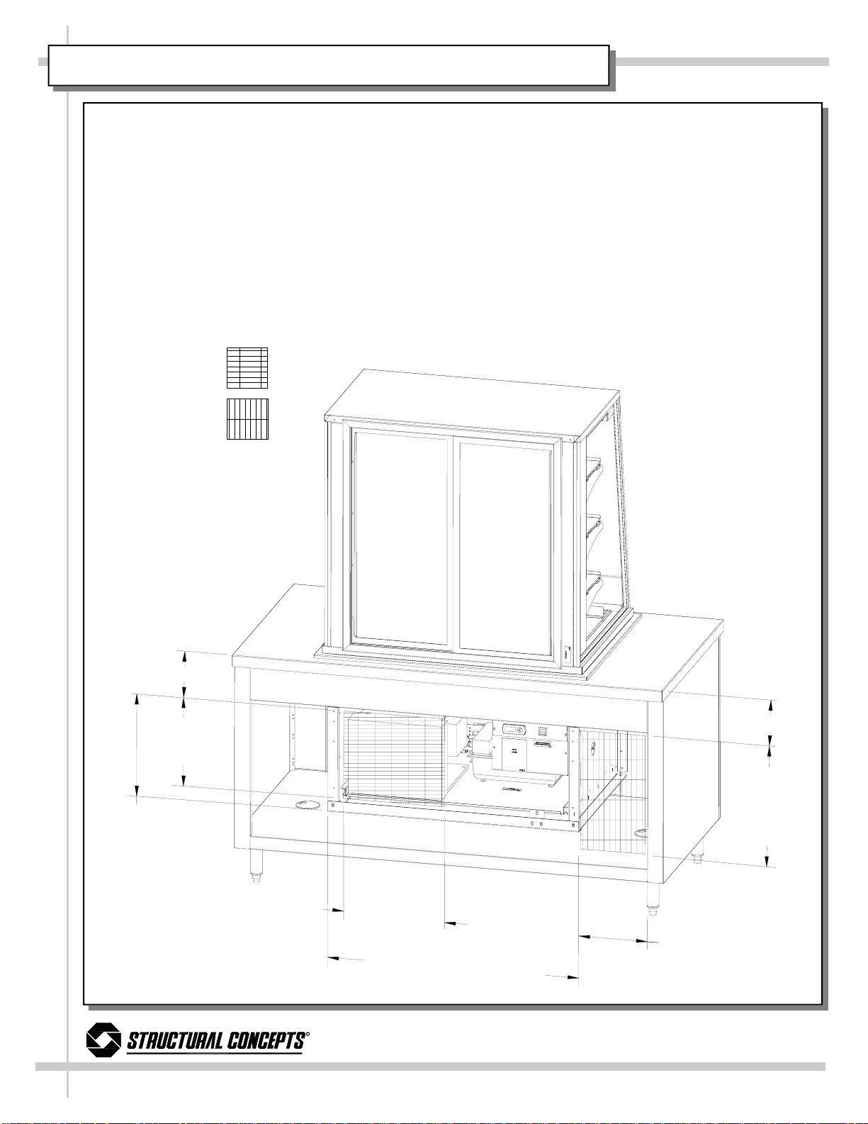
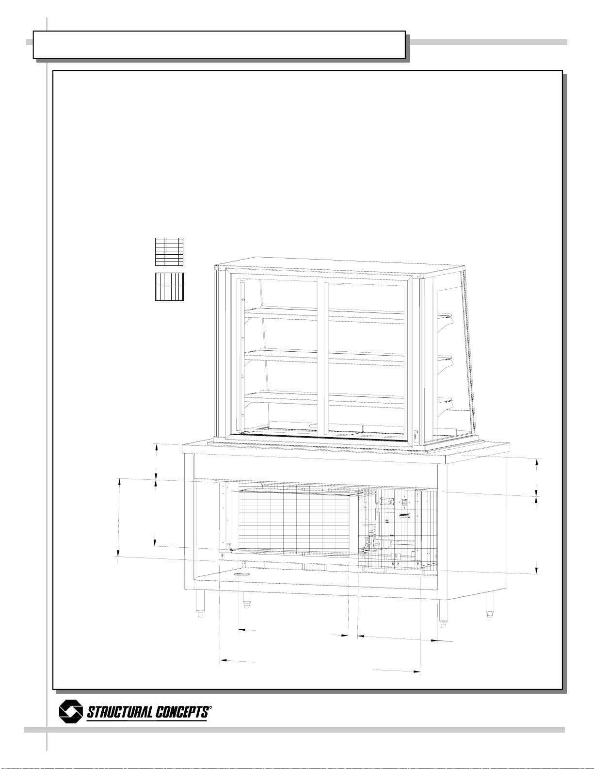
Service Top Cutout Dimensions
Note: See Manual Cover for DO3637R, DO4837R,
DO3623R & 4823R Service Top Cutout Dimensions.
Clearance Dimensions
The Refrigerated section must maintain airflow clearance. Dimensions are as follow.
1. 4" Minimum Spacing from bottom of refrigeration
frame to bottom of cabinet or floor required for adequate air flow.
2. 9 1/2" Countertop / Facia enclosure space on cabinets or counter to allow for pullout system slide-out.
3. 15" Minimum opening in back of cabinet or counter
(to pull out refrigeration system).
4. Back of counter / cabinet must be vented at specific
sizes to allow for proper air intake and air exhaust.
See Venting Instructions sections for specifics.
5. Obstruction or restriction of air can void warranty.
Note: See Venting Instructions sections (next two
pages) for more specific Air Intake and Air Exhaust
clearance dimensions for Models DO3637R &
DO4837R.
9 1/2” (SEE
NOTE 2)
15”
(SEE NOTES
3 & 4)
4” (SEE NOTE 1)
ABOVE ILLUSTRATION APPLIES TO BOTH
MODELS DO3637R AND DO4837R
R
888 Porter Rd. Muskegon, MI 49441 Phone: 231.798.8888 Fax: 231.798.4960 www.structuralconcepts.com
5
Page 6
VENTING INSTRUCTIONS FOR AIR INTAKE / EXHAUST - DO3637R
BACK VIEW OF CABINET
AFTER POSITIONED ON
CUSTOMER-SUPPLIED COUNTER/BASE
Warning: The minimum intake and exhaust areas must be allowed (as illustrated
below) or case temperatures may fluctuate beyond safe parameters.
NOTES:
1. BACK OF CABINET MUST BE VENTED A MINIMUM OF 13” x 13” FOR AIR INTAKE.
2. BACK OF CABINET MUST BE VENTED A MINIMUM OF 10 1/2” x 19” FOR AIR EXHAUST.
3. BACK OF CABINET MUST PROVIDE A MINIMUM OF 15” x 32” FOR MAINTENANCE ACCESS. THIS AREA (AS
DIMENSIONED BELOW) WILL ALLOW SERVICE TO SLIDE OUT CONDENSING UNIT.
4. SEE REFRIGERATION FUNDAMENTALS FOR VIEW OF CONDENSING UNIT AFTER SLIDE-OUT.
5. AIR INTAKE
(ILLUSTRATED
BELOW).
6. AIR EXHAUST
(ILLUSTRATED
BELOW).
9
1
/
2
”
F
AC
I
A
E
N
C
L
O
S
U
R
E
9
1
/
2
”
1
3
”
M
I
N
I
M
U
M
A
I
R
I
S
P
1
5
”
M
I
N
I
M
U
M
M
A
I
N
T
A
C
S
P
E
N
A
N
C
E
C
A
E
S
S
C
E
N
T
A
K
E
A
C
E
M
E
1
3
”
M
IN
I
M
U
M
A
I
N
T
A
K
E
3
2
R
888 Porter Rd. Muskegon, MI 49441 Phone: 231.798.8888 Fax: 231.798.4960 www.structuralconcepts.com
I
R
S
P
A
C
E
”
M
I
N
I
M
U
M
M
A
I
N
T
E
N
A
N
C
E
A
C
C
E
S
S
S
P
A
C
E
1
0
1
/
2
”
M
IN
.
A
I
R
S
P
A
E
X
H
A
U
S
T
C
E
1
9
”
I
N
I
M
U
M
A
I
R
X
H
A
U
S
T
S
P
A
C
E
6
Page 7
VENTING INSTRUCTIONS FOR AIR INTAKE / EXHAUST - DO4837R
BACK VIEW OF CABINET
AFTER POSITIONED ON
CUSTOMER-SUPPLIED COUNTER/BASE
Warning: The minimum intake and exhaust areas must be allowed (as illustrated
below) or case temperatures may fluctuate beyond safe parameters.
NOTES:
1. BACK OF CABINET MUST BE VENTED A MINIMUM OF 13” x 25” FOR AIR INTAKE.
2. BACK OF CABINET MUST BE VENTED A MINIMUM OF 19” x 21” FOR AIR EXHAUST.
3. BACK OF CABINET MUST PROVIDE A MINIMUM OF 15” x 45” FOR MAINTE NANCE ACCESS. THIS AREA
(AS DIMENSIONED BELOW) WILL ALLOW SERVICE TO SLIDE OUT CONDENSING UNIT.
4. SEE REFRIGERATION FUNDAMENTALS FOR VIEW OF CONDENSING UNIT AFTER SLIDE-OUT.
5. AIR INTAKE
(ILLUSTRATED
BELOW).
6. AIR EXHAUST
(ILLUSTRATED
BELOW).
MA
A
9
1
/
2
”
1
3
”
M
I
N
I
M
U
M
A
I
R
S
1
5
”
MI
N
I
MU
M
I
N
T
C
C
E
S
E
N
A
N
C
E
S
S
P
A
C
E
I
N
T
A
K
E
P
A
C
E
R
888 Porter Rd. Muskegon, MI 49441 Phone: 231.798.8888 Fax: 231.798.4960 www.structuralconcepts.com
F
A
C
I
A
E
N
C
L
O
S
U
R
E
2
5
”
M
I
N
I
M
U
M
A
IR
I
N
T
A
K
E
S
4
5
”
M
I
N
I
M
A
C
C
2
”
P
A
C
E
U
M
M
A
I
N
E
S
S
S
P
A
T
E
N
A
N
C
E
C
E
1
9
”
M
I
N
I
M
U
A
I
R
S
P
A
M
E
X
H
A
U
S
C
E
9
1
/
2
”
1
5
”
M
I
N
I
M
U
M
A
I
R
E
X
H
A
U
S
T
S
T
P
A
C
E
7
Page 8
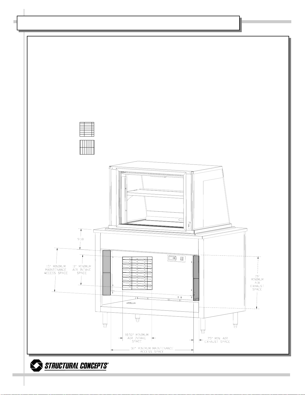
VENTING INSTRUCTIONS FOR AIR INTAKE / EXHAUST - DO3623R & DO4823R
BACK VIEW OF CABINET
AFTER POSITIONED ON
CUSTOMER-SUPPLIED COUNTER/BASE
Warning: The minimum intake and exhaust areas must be allowed (as illustrated
below) or case temperatures may fluctuate beyond safe parameters.
NOTES:
1. BACK OF CABINET MUST BE VENTED A MINI MUM OF 10 1/2” x 11” FOR AIR INTAKE.
2. BACK OF CABINET MUST BE VENTED A MINIMUM OF 3/4” x 15” FOR AIR EXHAUST.
3. BACK OF CABINET MUST PROVIDE A MINIMUM OF 15” x 32” FOR MAINTE NANCE ACCESS. THIS AREA
(AS DIMENSIONED BELOW) WILL ALLOW SERVICE TO SLIDE OUT CONDENSING UNIT.
4. SEE REFRIGERATION FUNDAMENTALS FOR VIEW OF CONDENSING UNIT AFTER SLIDE-OUT.
5. AIR INTAKE
(ILLUSTRATED
BELOW).
6. AIR EXHAUST
(ILLUSTRATED
BELOW).
R
888 Porter Rd. Muskegon, MI 49441 Phone: 231.798.8888 Fax: 231.798.4960 www.structuralconcepts.com
8
Page 9
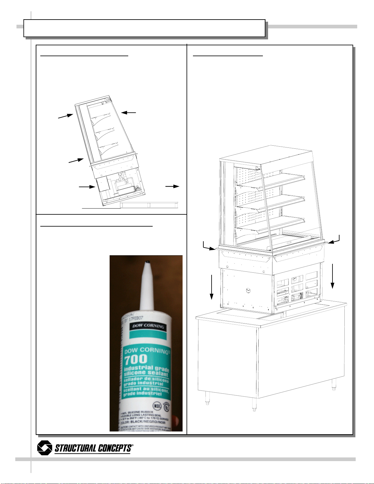
INSTALLATION
1. Remove Case From Skid
Caution: Case must always remain supported
or center of gravity may allow case to fall. Slide
to rear of skid and tip backward off skid while
maintaining support. See illustration below.
Upper
Display
d
l
o
H
y
l
m
r
i
F
C
Refrigerated
a
e
R
W
e
s
a
S
a
C
o
r
F
Drop-In
Section
o
r
i
h
i
d
i
l
e
s
S
m
f
e
l
g
n
f
f
O
d
i
k
Case
Slide
Skid
Out
3. Seal Upper Display Case to Base
• NSF® Listed Industrial Grade Silicone Seal-
ant is recommended.
• Clip tip to allow approximately 1/8” to 3/16”
diameter hole.
• Beginning at case
rear, run a consistent, solid bead of
silicone around
entire perimeter.
2. Display Case Setup
• SCC® Service Drop-In Refrigerated Merchan-
diser Case consists of two sections: The Upper
Display Case and Drop-In Refrigerated Section.
• As both sections make up one conjoined unit, it
is both large and heavy. A team effort is required for lowering Case into the Customer Supplied Base.
• After lowering into Base, adjust into position al-
lowing Case to gingerly rest on Counter Top
without marring.
Seal
Seal
Along
Along
Here
Here
r
e
m
o
t
s
u
C
p
u
S
B
R
888 Porter Rd. Muskegon, MI 49441 Phone: 231.798.8888 Fax: 231.798.4960 www.structuralconcepts.com
d
e
i
l
p
e
s
a
9
Page 10

START-UP AND OPERATION
Case Start-Up
• Plug cord into a certified electrical outlet with
ground.
• Turn on the Main Power Switch. Switch is in
the Drop-In Refrigerated Section on the rear
right hand side of base.
• The Temperature Control Module (LED) will
illuminate. Evaporator coil fans and the
compressor motor should turn on.
• From the front of the case, raise the deck to
confirm that the coil fans are functioning
properly.
• Turn on the lights. Light Switch is in the Up-
per Display interior of the case at rear right
side (see illustration at right).
• First time lighting may require a short warm
up period for the bulbs. Slightly dim or a
flickering of new bulbs is normal.
Temperature Settings
• This case has been tested to maintain a
temperature at or below 5° Celsius / 41°
Fahrenheit.
• When the merchandiser is in a start up
mode or has been idle for a long period of
time, the unit will require 30 minutes in order
to pull-down to temperature.
• Spirit-Filled Thermometer located in refriger-
ated compartment is for monitoring warmest
air temperature in accordance with NSF®
Std. 7 (see illustration at right).
• The temperature is controlled by a Tempera-
ture Control Module. It is located at the
lower-right area (from the case rear) of the
Drop-In Refrigerated Section. See top-right
illustration for general location.
• If a temperature setting change is
required,refer to the instructions for the
CPC® (ESC3) Temperature Control
Programming operating section of this manual
• Note: See Technical Data section of this
manual for proper settings to maintain product temperature per model.
Upper
Display
Case
Shelves
Deck
Drop-In
Refrigerated
Section
— Upper Display Case & Drop-In Refrigeration Section —
ON
OFF
—– Main Power “Rocker” Switch —–
Condensate
Pan
Light
Switch
Spirit-Filled
Thermometer
(see illustration below)
Main
Power
“Rocker”
Switch
Temperature
Control Module
—– Spirit-Filled Thermometer —–
R
888 Porter Rd. Muskegon, MI 49441 Phone: 231.798.8888 Fax: 231.798.4960 www.structuralconcepts.com
10
Page 11

MAINTENANCE FUNDAMENTALS
Adjustable Shelf
• Adjustment of the angle of the shelves can be
made by pivoting the lower portion of the shelf
bracket in the upright.
• The shelves can be adjusted to an angle of: 0,
5, and 10 degrees.
• See illustration at right.
Shelf Assembly Removal
• Shelves can be removed for cleaning or ad-
justments
• For lighted shelving, turn off power, unplug the
light cord.
• Lift shelf straight up to separate from brackets.
• Remove brackets. Note it may be necessary
to remove the nylon shipping bracket retainer.
Pliers will be required to accomplish this task.
Light Fixtures
Light fixtures are located at the top inside of case
(from the front) and may be provided on the underside of each shelf assembly
Removal of lamp:
• Rotate lamp (1/4 turn) so that pins are aligned
in slots and remove bulb.
Installation of lamp:
• Align pins with slot.
• Insert pins into socket and rotate 1/4 turn to
secure pin contacts in socket.
See illustration at lower right.
Bracket Retainers
Light Fixtures
Light Socket
Shelf Assembly
Shelf Bracket
Adjustment
Notches
Light Fixture
Lamp Pins
R
888 Porter Rd. Muskegon, MI 49441 Phone: 231.798.8888 Fax: 231.798.4960 www.structuralconcepts.com
11
Page 12

MAINTENANCE FUNDAMENTALS, CONTINUED
Warning, disconnect power before providing maintenance and service to unit. Assembly or disassembly and servicing to be
accomplished by licensed electrical contractor.
Evaporator Coil Fans Access and Removal
• Fans may be accessed by removing Deck
(covering Fan Shroud, Fan Housing and
Coil). See illustrations at right.
Light Ballast Access
Light ballast is located inside the Electrical JBox. Electrical J-Box is located at lower-right
side (from the rear) of the Drop-In Refrigerated
Section. See below right illustration for general
location.
Electrical J-Box is assembled with Phillips
screws. To disassemble, simply use Phillips
screwdriver to remove screws.
Removing Rear Doors and Perforated
Acrylic Plenum.
• Note: Doors are not interchangeable.
• There is an Outer and Inner Door. The
Outer door is the right hand door (from
case rear). It can be identified by a stop
located at the lower right hand corner to the
inside of the case.
• The Inner Door is the left hand door (from
case rear).
• See next page for specifics on access to
and removal of thumbscrews, doors and
perforated acrylic plenum.
Fan
Shroud
Fan
Housing
Inner Door
Coil
Fan Shroud
Fan & Housing
Coil
Drain
Outer
Door
Thumbscrews
holding
Sliding
Doors to
Acrylic
Plenum
R
888 Porter Rd. Muskegon, MI 49441 Phone: 231.798.8888 Fax: 231.798.4960 www.structuralconcepts.com
12
Page 13

MAINTENANCE FUNDAMENTALS, CONTINUED
Removing the Rear Doors
• Remove Thumbscrews (4 each side).
Thumbscrew removal will allow Rear
Doors to be removed.
• See illustration on this page for locations
of Thumbscrews, Nuts, Perforated
Acrylic Plenum, etc.
• Move the doors toward the center of the
case.
• Starting with the Outer Door (right hand
door from rear of the case), individually
lift each door up toward top of the case
and pivot the bottom of door out.
• Rear Doors (both Outer and Inner) must
be replaced in the same manner in which
they are removed.
Removing Perforated Acrylic Plenum
• After Outer and Inner Doors are re-
moved, the Perforated Acrylic Plenum
pieces can now be removed.
• Slide the Plenum toward the center of
the case.
• Starting with the right hand Plenum, lift
up toward the top of the case and pivot
the bottom Plenum out.
• Perforated Acrylic Plenum pieces must
be replaced in the same manner in which
they are removed.
Shelving
Lamp
View of thumbscrew
(4 each side) to be removed.
Thumbscrew
Upright
View of Thumbscrew
and Nut from Case
Rear. Note: Thumbscrews are only accessible from front of case.
Thumbscrew and Nut
Shelving
Bracket
Additional view of
from Case Rear.
View of Perforated
Acrylic Plenum
View of Rear
Outer Door
R
888 Porter Rd. Muskegon, MI 49441 Phone: 231.798.8888 Fax: 231.798.4960 www.structuralconcepts.com
13
Page 14

REFRIGERATION FUNDAMENTALS
Refrigeration Access, Connections &
Servicing
Assembly or disassembly and servicing to
be accomplished by licensed refrigeration
contractor.
• Refrigeration Unit slides directly out from
lower section to allow for servicing.
• Service connections are located in the
Refrigeration Slide-Out (shown at right).
• Refrigeration Unit is equipped with
evaporator pan for case condensation.
Insure evaporator pan is plugged in 110V
receptacle inside base, and positioned
under PVC drain and on base frame.
• When pulling or pushing unit in or out under
the case, use caution to avoid damage to
copper refrigeration lines, hoses and cable.
• Insure that the flexible drain hose is fully
inserted into the slot of hose support for
proper drainage. See illustration on next
page for general location and specifics.
Temperature Control Module
• Temperature Control Module is located in
the Electrical J-Box.
• The temperature is controlled by the
Temperature Control Module. It is located
at lower-right area (from the rear) of the
Drop-In Refrigerated Section. See top-right
illustration for general location.
• If a temperature setting change is required,
refer to the instructions for the CPC®
(ESC3) Temperature Control Programming
operating section of this manual
• Note: See Technical Data section of this
manual for proper settings to maintain
product temperature per model.
Temperature
Control
Module
Temperature
Control
Module
Sl
i
d
Se
e
r
r
o
t f
u
O
g
n
i
c
i
v
Light Ballast
Electrical
J-Box
Main Power
Switch
R
888 Porter Rd. Muskegon, MI 49441 Phone: 231.798.8888 Fax: 231.798.4960 www.structuralconcepts.com
14
Page 15

REFRIGERATION SLIDE-OUT EXPLODED PICTORIAL
The following images show the various parts pertaining to the Refrigeration
Unit (that is slid directly out from lower section) to be serviced.
Sight Glass
Condensate
Pan
Copper
Tubing
Electrical
Junction Box
Refrigeration
Service Valve
Flexible Hose
Connections
Condensing Coil
(and internal fan)
Capacitor
Receiver
Condensing
Unit
Dryer Filter
R
888 Porter Rd. Muskegon, MI 49441 Phone: 231.798.8888 Fax: 231.798.4960 www.structuralconcepts.com
Copper
Tubing
15
Page 16

TECHNICAL INFORMATION SHEET - MODEL DO3637R
R
888 Porter Rd. Muskegon, MI 49441 Phone: 231.798.8888 Fax: 231.798.4960 www.structuralconcepts.com
16
Page 17

TECHNICAL INFORMATION SHEET - MODEL DO4837R
R
888 Porter Rd. Muskegon, MI 49441 Phone: 231.798.8888 Fax: 231.798.4960 www.structuralconcepts.com
17
Page 18

TECHNICAL INFORMATION SHEET - MODEL DO3623R
R
888 Porter Rd. Muskegon, MI 49441 Phone: 231.798.8888 Fax: 231.798.4960 www.structuralconcepts.com
18
Page 19

TECHNICAL INFORMATION SHEET - MODEL DO4823R
R
888 Porter Rd. Muskegon, MI 49441 Phone: 231.798.8888 Fax: 231.798.4960 www.structuralconcepts.com
19
Page 20

TROUBLESHOOTING
Product is Drying Out
Water on the Floor
Excessive Fan Noise
System is not Operating
Fans Not Working
Check the relative humidity in the store.
Check that all of the hoses are connected.
Check that the drain trap is free of debris.
Check that the case is aligned properly.
Check that nothing is obstructing the blade rotation.
Check that the fan shroud is properly secured.
Confirm the utility power is on.
Check that the MAIN power switch is on.
Check that the unit is properly plugged in.
Check the circuit breaker box for tripped circuits.
Check that the MAIN power switch is on.
Case Lights Not Working
Condensing Unit Not
Operating.
Determine if there is ice build up blocking the fan.
Check bulbs for proper installation and connection.
Check for burned out bulbs.
Clean dirt and dust from the bulbs to prevent flickering.
LED dF flashing, Controller is in defrost mode (not an alarm).
Compressor is running in a normal condition.
Check that the power is turned on.
Review factory time settings on the CPC controller.
R
888 Porter Rd. Muskegon, MI 49441 Phone: 231.798.8888 Fax: 231.798.4960 www.structuralconcepts.com
20
Page 21

TROUBLESHOOTING, CONTINUED
Alarm Going Off, CPC ESC3
Not Holding Temperature.
E0 flashing, Air probe has failed.
E1 flashing, Defrost termination or product probe has failed.
L0 flashing, Low temperature alarm.
H1 flashing, High temperature alarm.
Ed flashing, Defrost timeout has occurred (did not terminate
correctly).
dF flashing, Controller is in defrost mode (not and alarm).
Compressor is running is a normal condition.
If a large amount of warm product was added to the case, it will
take time for the temperature to adjust.
The temperature will change during defrost mode but will return
to normal.
Check that the discharge air is not disrupted or blocked by
product (Product is above load limit level).
Check that the case is not in the sun or near a heat or airconditioning vent.
Is case located near front doors.
Check the evaporator coil for ice build up (can be viewed from
fan shroud inspection cover).
R
888 Porter Rd. Muskegon, MI 49441 Phone: 231.798.8888 Fax: 231.798.4960 www.structuralconcepts.com
21
Page 22

CLEANING SCHEDULE
Cleaning
Daily Weekly Monthly
Clean Case Exterior X
X
X
Clean Case Interior X
X
X
X
Task
Clean outside surface of front curved glass
with a household or commercial glass
cleaner.
Clean wood, laminate and painted surfaces
with a mild soap and water solution and a
soft cloth .
Remove rear panel. Clean under case with
vacuum.
Shelves may be cleaned with a household
or commercial glass cleaner.
Remove the decks and clean with soap and
water.
Remove rear doors and clean with a household or commercial cleaner
Vacuum tub under deck if necessary. To
flush out the tub, disconnect power to the
case. Remove the deck and the fan
shroud. Direct drain to floor drain or a
bucket. Run hose into the drain to flush out
debris. Hose out the tub.
X
X
X
R
888 Porter Rd. Muskegon, MI 49441 Phone: 231.798.8888 Fax: 231.798.4960 www.structuralconcepts.com
Keep drains clean and free of debris which
could clog the drain and rob the case of
needed refrigeration.
Using air pressure if available, or an industrial strength vacuum, clean the dust and
dirt that collects on the condenser coil. (Be
careful not to damage the fins on the coil.)
Slide out Refrigeration Unit and use a vacuum with a hose attachment to clean area.
22
Page 23

CPC® CONTROLLER - OVERVIEW
Controller Overview
The CPC® ESC3 series is an electronic refrigeration controller that provides control of compressor,
fan and defrost management. The ESC3 provides control of a compressor (or solenoid) valve in response to temperature variations.
Temperature Control
Temperature control in the ESC3 is accomplished by comparing the temperature reading of the case
temperature probe against the temperature set point. The compressor output is used to control the
temperature. If the temperature is above the temperature set point (LI) + the hysteresis set point (rd),
the compressor output is turned on. If the temperature is below the temperature set point - the hysteresis set point, the compressor output is turned off.
Compressor Control
Several setpoints are available that allow the operation of the compressor output to be tailored to
match individual needs.
Min ON/Off Times and Minimum Cycle Time
Minimum ON/OFF compressor times can be specified, as well as a minimum time delay between
compressor cycles. These parameters help prevent short cycling.
Compressor Power On Delay
Compressor power on delay setpoint (c0) allows the user to specify a delay after the power-up of the
controller. The compressor output will not come on regardless of the temperature reading until this
amount of time has expired.
Compressor Safety Cycle
The Compressor Safety Cycle setpoint (c4) specifies a cycle time that the compressor is to be cycled
if the temperature sensor used for control fails. If this setpoint is 0, the compressor will be off. If this
setpoint is 100, the compressor will be on. Any value between 1 and 99 will result in the compressor
being on for that period of time. At the end of this time, the compressor will be shut off for approximately 15 minutes.
R
888 Porter Rd. Muskegon, MI 49441 Phone: 231.798.8888 Fax: 231.798.4960 www.structuralconcepts.com
23
Page 24

CPC® - ESC3 CONTROLLER OPERATION
Interface - The ESC3 features a 3 digit LED display that shows the case
temperature. Alternately, the display can be configured to display the product
-15
temperature if a product temperature probe is connected. The temperature
0
can be displayed in either
C or 0F.
Alarm Key - The Alarm key illuminates when the controller has detected an alarm condition.
This key is also used to reset an alarm condition and to enter the setup mode (allowing set
points to be changed).
Compressor Key - The Compressor key illuminates when the compressor output is on.
When the ESC3 is in setup mode, this key is used to select a set point to be modified and to
change the value of the set point.
Defrost Key - The Defrost key illuminates when the ESC3 is in defrost mode. Press the defrost key for 5 seconds to go into manual defrost mode. The key is also used in setup mode
to select a setpoint to be modified and to change the value of the set point.
Alarm Operation - The ESC3 has several alarm functions. In addition to alarms based on air temperatures, it will alarm if a probe failure is detected.
Indications on the Display
If the defrost, or compressor key blinks. It means that the corresponding function is delayed by a timing routine or inhibited.
Code Meaning
E0 Air probe has failed.
E1 Defrost termination or product probe has failed.
L0 Low temperature alarm.
HI High temperature alarm.
Ed Defrost timeout has occurred (did not terminate correctly).
dF
Controller is in defrost mode (not and alarm).
R
888 Porter Rd. Muskegon, MI 49441 Phone: 231.798.8888 Fax: 231.798.4960 www.structuralconcepts.com
24
Page 25
CPC® ESC3 SET POINT CHANGING INSTRUCTIONS
Viewing and Changing the Temperature Set Point
The temperature set point is the comparison point for the control temperature input.
To change the set point value:
1. Press the Alarm key for 3 seconds, until the set point is displayed and blinking.
2. Press the compressor key or defrost key to raise/lower the value.
3. Press the Alarm key again to accept the new value.
Changing Other Set Points
There are two levels of set points in the ESC3. The first level does not require a password to change
(unless the buttons are locked out). The set points that can be changed in this manner are identified
in table 1 as a USER set point All other set points do require a password to change and are identified in table 2 as an OEM set point.
Note: Table 2 can be obtained from OEM upon request.
To change USER set points:
1. Press the alarm key and hold it until the letters PS are displayed.
2. Use the compressor and defrost keys to scroll through the codes for the different set points (see
Table 1).
3. When the code is displayed for the set point you wish to change, press the alarm key. The value
for that set point will be displayed.
4. Press the compressor or defrost key to change the value.
5. Press the alarm key to go back to the code.
At this point you must press the alarm key to accept the change or press the compressor or defrost
key to scroll to the next USER set point. To accept the changes, press and hold the alarm key until
the display stops flashing.
R
888 Porter Rd. Muskegon, MI 49441 Phone: 231.798.8888 Fax: 231.798.4960 www.structuralconcepts.com
25
Page 26

WARRANTY
All sales by Structural Concepts Corporation (SCC) are subject to the following limited warranty. “Goods” refers to the product or products being sold by SCC.
Warranty; Remedies; Limitations. SCC warrants that if any Goods are found by an authorized representative of SCC not to be of good material or workmanship
within one year of the date of shipments SCC will, at its option after inspection by an authorized representative, replace any defective Good or pay the reasonable
cost of replacement for any such defective Goods, provided that written notice of the defect is given to SCC within 30 days of the appearance of such defect. If
notice is not given within such period, any claim for breach of warranty shall be conclusively deemed to have been waived and SCC shall not be liable under this
warranty. If SCC is unable to repair or replace the defective Goods, SCC shall issue a credit to the Purchaser for all or part of the purchase price, as SCC shall
determine. The replacement or payment in the manner described above shall be the sole and exclusive remedy of Purchaser for a breach of this warranty. If any
Goods are defective or fail to conform to this warranty, SCC will furnish instructions for their disposition. No Goods shall be returned to SCC without its prior consent.
SCC’s liability for any defect in the Goods shall not exceed the purchase price of the Goods. SCC SHALL HAVE NO LIABILITY TO PURCHASE FOR CONSEQUENTIAL DAMAGES OF ANY KIND WHATSOEVER, INCLUDING, BUT NOT LIMITED TO, PERSONAL INJURY, PROPERTY DAMAGE, LOST PROFITS, OR
OTHER ECONOMIC INJURY DUE TO ANY DEFECT IN THE GOODS OR ANY BREACH OF SCC, SCC SHALL NOT BE LIABLE TO THE PURCHASER IN
TORT FOR ANY NEGLIGENT DESIGN OR MANUFACTURE OF THE GOODS, OR FOR THE OMISSION OF ANY WARNING THEREFROM.
SCC shall have no obligation or liability under this warranty for claims arising from any other party’s (including Purchaser’s) negligence or misuse of the Goods or
environmental conditions. This warranty does not apply to any claim or damage arising for or cause by improper storage, handling, installation, maintenance, or
from fire, flood, accidents, structural defects, building settlement or movement, acts of God, or other causes beyond SCC’s control.
Except as expressly stated herein, SCC makes no warranty, express, implied, statutory or otherwise as to any parts or goods not manufactured by SCC. SCC
shall warrant such parts or Goods only (I) against such defects, (II) for such periods of time, and (III) with such remedies, as are expressly warranted by the manufacturer of such parts of Goods. Notwithstanding the foregoing, any warranty with respect to such parts of Goods and any remedies available as a result of a
breach thereof shall be subject to all of the procedures, limitations, and exclusions set forth herein.
THE WARRANTIES HEREIN ARE IN LIEU OF ALL WARRANTIES, EXPRESS, IMPLIED, STATUTORY, OR OTHERWISE. IN PARTICULAR, SCC MAKES NO
WARRANTY OF MERCHANTABILITY OR FITNESS FOR A PARTICULAR PURPOSE.
No representative, agent or dealer of SCC has authority to modify, expand, or extend this Warranty, to waive any of the limitations or exclusions, or to make any
different or additional warranties with respect to Goods.
Period of Limitations. No claim, suit or other proceeding may be brought by Purchaser for any breach of the foregoing warranty or this Agreement by SCC or in
any way arising out of this Agreement or relating to the Goods after one year from the date of the breach. In the interpretation of this limitation on action for a
breach by SCC, it is expressly agreed that there are no warranties of future performance of the goods that would extend that period of limitation herein contained
for bringing an action.
Indemnifications. Purchaser agrees to indemnify, hold harmless, and defend SCC if so requested, from any and all liabilities, as defined herein, suffered, or
incurred by SCC as a result of, or in connection with, any act, omission, or use of the Goods by Purchaser, its employees or customers, or any breach of this
Agreement by Purchaser. Liabilities shall include all costs, claims, damages, judgments, and expenses (including reasonable attorney fees and costs).
Remedies of SCC. SCC’s rights and remedies shall be cumulative and may be exercised from time to time. In a proceeding or action relating to the breach of this
Agreement by Purchaser, Purchaser shall reimburse SCC for reasonable costs and attorney’s fees incurred by SCC. No waiver by SCC of any breach of Purchaser shall be effective unless in writing nor operate as a waiver of any other breach of the same term thereafter. SCC shall not lose any right because it has not
exercised it in the past.
Applicable Law. This Agreement is made in Michigan and shall be governed by and interpreted according to Michigan law. Any lawsuit arising out of this Agreement or the Goods may be handled by a federal or state court whose district includes Muskegon County, Michigan, and Purchaser consents that such court shall
have personal jurisdiction over Purchaser.
Miscellaneous. If any provision of this Agreement is found to be invalid or unenforceable under any law, the provision shall be ineffective to that extent and for the
duration of the illegality, but the remaining provisions shall be unaffected. Purchaser shall not assign any of its rights nor delegate any of this obligations under this
Agreement without prior written of SCC. This Agreement shall be binding upon and inure to the benefit of SCC and Purchaser and each of their legal representatives, successors and assigns.
SCC warrants its products to be free of defects in materials and workmanship under normal use and service for a period of one (1) year from the date of delivery.
This warranty is extended only to the original purchaser for use of the Goods. It does not cover normal wear parts such as plastic tongs, tong holders, tong cables,
bag holders, or acrylic dividers.
General Conditions. All service labor and/or parts charges are subject to approval by SCC. Contact the Customer Service Department in writing or call 231-798-
8888.
All claims must contain the following information: (1) the model and serial code number of the equipment; (2) the date and place of installation; (3) the name and
address of the agency which performed the installation; (4) the date of the equipment failure; and (5) a complete description of the equipment failure and all circumstances relating to that failure.
Once the claim has been determined to be a true warranty claim by SCC’s Customer Service Department, the following procedure will be taken: (1) replacement
parts will be sent at no charge from SCC on a freight prepaid basis; (2) reimbursement for service labor will be paid if the following conditions have been met— (a)
prior approval of service agency was awarded from the Customer Service Department; and (b) an itemized statement of all labor charges incurred is received by
the Customer Service Department. The cost of the service labor reimbursement will be based on straight time rates and reasonable time for the repair of the defect.
If problems occur with any compressor, notify SCC’s Customer Service Department immediately. Any attempt to repair or alter the unit without prior consent from
the Customer Service Department will render any warranty claim null and void. This warranty and protection plan does not apply to any condensing unit or any part
thereof which has been subject to accident, negligence, misuse, or abuse, or which has not been operated in accordance with the manufacturer’s recommendations or if the serial number of the unit has been altered, defaced, or removed.
Limit of Liability. The limit of liability of SCC toward the exchange cost of the original condensing unit, F.O.B. SCC, Norton Shores, MI, of each motor-compressor
assembly replaced during the warranty shall not exceed manufacturer's current established wholesaler’s exchange price and in no case shall the labor of removing
or replacing the motor-compressor or parts thereof be the responsibility of SCC.
R
888 Porter Rd. Muskegon, MI 49441 Phone: 231.798.8888 Fax: 231.798.4960 www.structuralconcepts.com
26
Page 27

TECHNICAL SERVICE
TECHNICAL SERVICE DEPARTMENT
1.800.433.9489
R
888 Porter Rd. Muskegon, MI 49441 Phone: 231.798.8888 Fax: 231.798.4960 www.structuralconcepts.com
27
 Loading...