

Page 1
DIO-32.PCIe User Manual
Part Number 8004e
www.sealevel.com PO Box 830 Liberty, SC 29657 864.843.4343
Page 2

Table of Contents
©
INTRODUCTION......................................................................................................................... 1
BEFORE YOU GET STARTED ................................................................................................. 2
WHAT’S INCLUDED ...................................................................................................................... 2
OPTIONAL ITEMS.......................................................................................................................... 2
SOFTWARE INSTALLATION .................................................................................................. 3
LINUX INSTALLATION .................................................................................................................. 6
HARDWARE INSTALLATION ................................................................................................. 9
VERIFYING INSTALLATION ......................................................................................................... 11
PROGRAMMING THE DIO-32.PCI ....................................................................................... 12
PROGRAMMING FOR WINDOWS .................................................................................................. 12
PROGRAMMING FOR LINUX ........................................................................................................ 12
DIGITAL I/O INTERFACE ............................................................................................................ 12
INPUT PORTS .............................................................................................................................. 13
INPUT PORTS PIN ASSIGNMENTS (DB-37 FEMALE) .................................................................... 14
OUTPUT PORTS (REED RELAY) .................................................................................................. 14
OUTPUT PORTS (REED RELAY) PIN ASSIGNMENTS (DB-37 MALE) ........................................... 14
DB-78 FEMALE PIN ASSIGNMENTS (CARD EDGE CONNECTOR) ................................................. 15
DIRECT HARDWARE CONTROL .................................................................................................. 15
READING THE INPUTS ................................................................................................................. 15
READING THE OUTPUTS ............................................................................................................. 15
WRITING THE OUTPUTS ............................................................................................................. 15
REGISTER DESCRIPTION ............................................................................................................. 16
OPTIONAL 3093 MIGRATION CABLE (CA378) ........................................................................... 17
ELECTRICAL CHARACTERISTICS .................................................................................... 18
FEATURES .................................................................................................................................. 18
SPECIFICATIONS ......................................................................................................................... 18
EXAMPLE CIRCUITS .............................................................................................................. 19
APPENDIX A - TROUBLESHOOTING ................................................................................. 20
APPENDIX B - HOW TO GET ASSISTANCE ...................................................................... 23
APPENDIX C – SILK SCREEN – 8004E PCB........................................................................ 24
APPENDIX D - COMPLIANCE NOTICES ............................................................................ 25
FEDERAL COMMUNICATIONS COMMISSION STATEMENT ........................................................... 25
WARRANTY............................................................................................................................... 26
Sealevel Systems, Inc.
SL9207 Revision 3/2009
DIO-32.PCIe User Manual
Page 3
©
Introduction
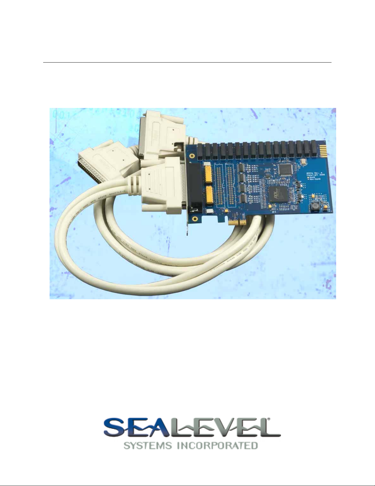
The DIO-32.PCIe digital I/O interface provides 16 optically isolated inputs and 16
reed relay outputs. The inputs protect the PC and other sensitive equipment from
spikes and ground loop current that can be generated in industrial environments,
while the outputs provide high quality, long life, low current (10 Watt maximum),
dry contact switch closures. Reed relays are well suited for low current applications.
The relays are normally open, and close when energized.
The SeaI/O Classic software drivers and utilities are included on the CD and make
installation and operation easy using Windows 2000, XP, Vista and Linux operating
systems. The SeaI/O API (Application Programmer Interface) provides a variety of
useful high-level function calls implemented as a Windows dynamic link library
(DLL) and as a Linux kernel module and library. SeaI/O also includes sample code
and utilities to simplify software development.
The inputs on the 8004e are rated for 3-13V. The inputs on the 8004He are rated for
10-30V.
Features
PCI Express X1 compliant
16 optically isolated inputs
Socketed dip resistor allows user configurable input range up to +30V
16 Reed relay outputs (SPST)
Highly reliable 10VA DIP Reed relays
Power (+5V and +12V) and ground provided on DB78 board connector
Includes 72” cable with DB78 Male connector to DB37 Male and DB37 Female
SeaI/O Classic software supports Windows 2000, XP and Vista operating
Software support for Linux available
connectors (Item# CA165)
systems
Sealevel Systems, Inc.
- 1 -
DIO-32.PCIe User Manual
Page 4
©
Before You Get Started
What’s Included
The DIO-32.PCIe is shipped with the following items. If any of these items is
missing or damaged please contact Sealevel for replacement.
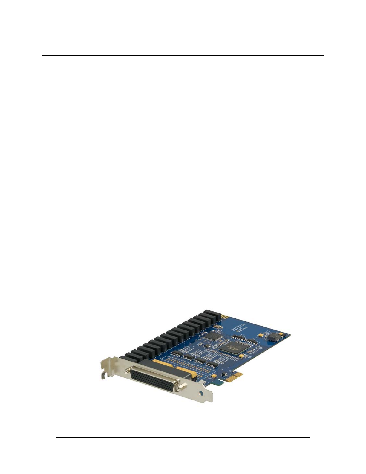
Item# 8004e – DIO-32.PCIe Digital I/O Adapter
• 8004e – Board with 3-13V inputs
• 8004He – Board with 10-30V inputs
Item# CA165 – DB78 Male to DB37 Male and DB37 Female V-cable
Sealevel Software CD – SeaI/O Classic software and user manual
Optional Items
Depending upon your application, you are likely to find one or more of the following
items useful for interfacing the DIO-32.PCIe to real-world signals. All items can be
purchased from our website (http://www.sealevel.com
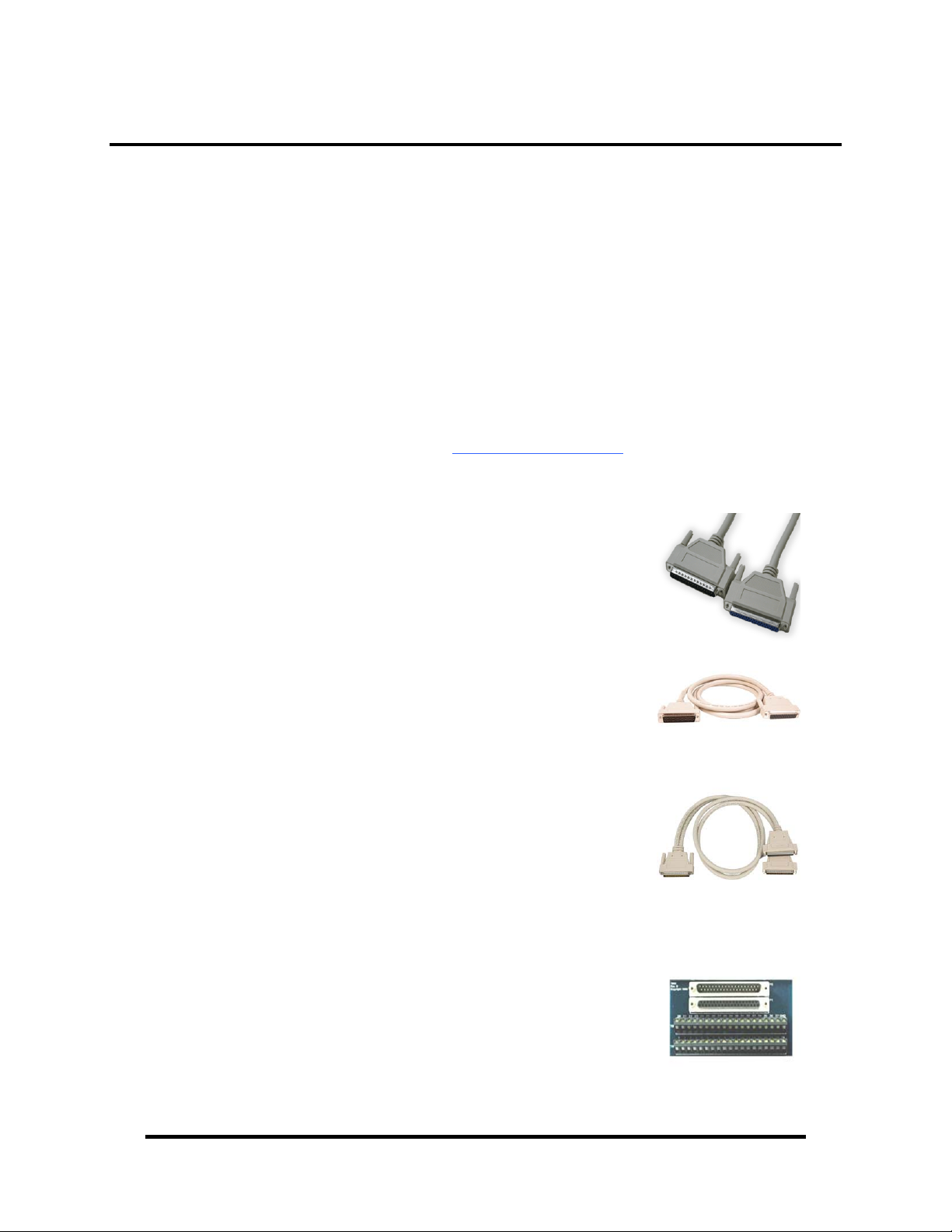
Cables
DB37 Male to DB37 Female Extension Cable
(Item# CA112)
) or by calling (864) 843-4343.
This cable provides a 6’ extension to the CA165. It has
one DB37 Male connector and one DB37 Female
connector.
DB78 Male to DB78 Female Extension Cable
(CA233)
This cable provides a 6’ extension to the DB78 board
connector on the 8004e. It has one DB78 Male
connector and one DB78 Female connector.
DB78M to DB37 Female and DB37 Male, for 3093
(Item# CA378)
The CA378 is designed specifically for customers using
the 3093 ISA digital I/O board that need to upgrade to
the 8004e PCIe board while preserving existing
infrastructure wiring. The CA378 connects to the 8004e
and provides an identical pin out to the 3093.
Terminal Blocks
DB37 Terminal Block (Item# TB02)
Break out serial and digital connectors to screw
terminals for easy field connection. The TB02 terminal
block is designed with both DB37 male and female
connectors for interfacing the inputs or outputs.
Sealevel Systems, Inc.
- 2 -
DIO-32.PCIe User Manual
Page 5
©
Software Installation
Windows 2000/XP/Vista™ Installation
Do not install the PCI Express board until the software
has been successfully installed.
1. Start Windows.
2. Insert the Sealevel Software CD in to your CD drive.
3. If ‘Auto-Start’ is enabled, the installation window will automatically appear.
Otherwise, navigate to the root directory of your CD drive and double-click
the ‘autorun.exe’ application to launch the installation window.
4. Select ‘Install’ to locate the software and manual for your device.
5. Type in the part number for your device (Item# 8004e) or select it from the
list in the drop box.
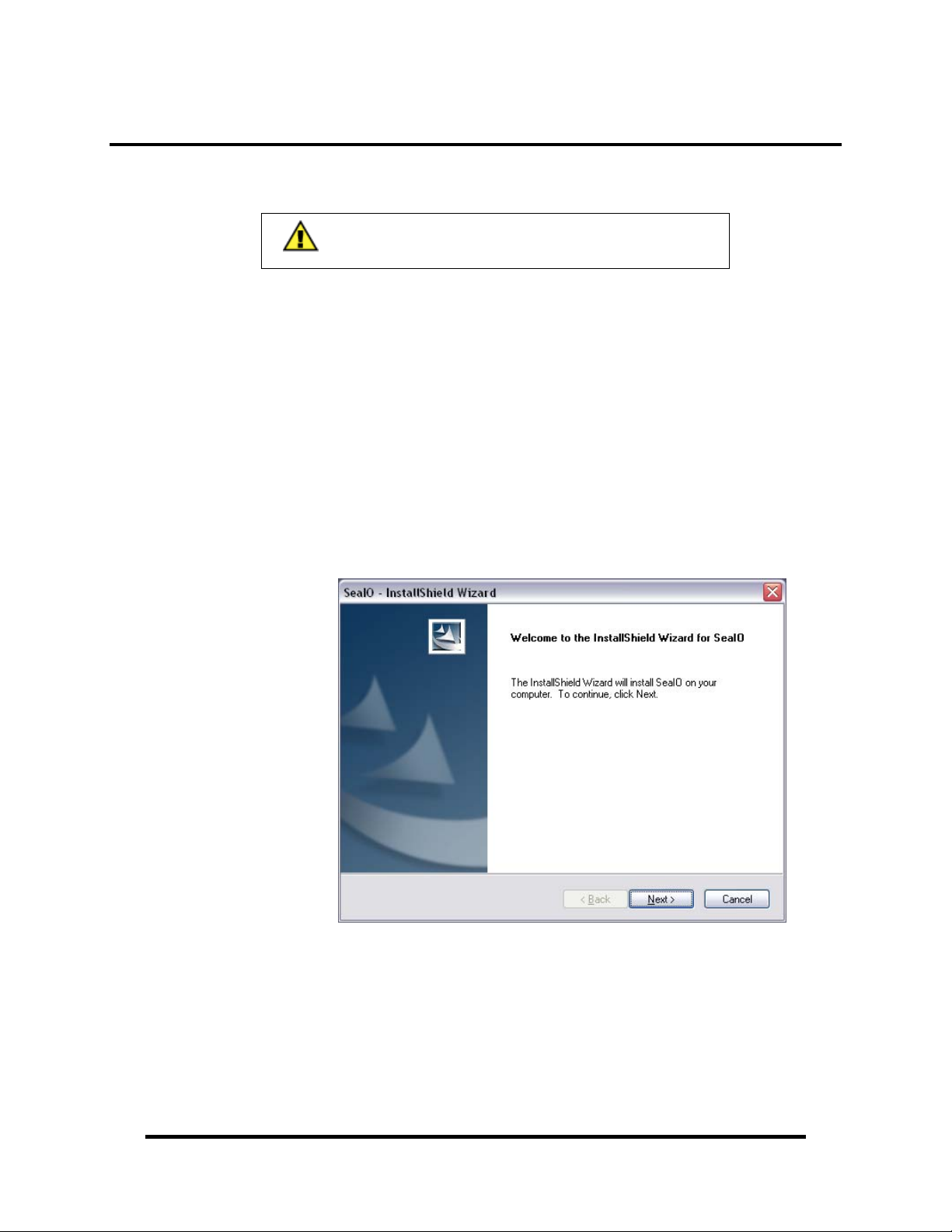
6. Click the ‘Install Drivers’ button to launch the Installation Wizard.
7. When the ‘SeaI/O - InstallShield Wizard’ window appears, click the ‘Next’
button to initiate the software installation.
Sealevel Systems, Inc.
- 3 -
DIO-32.PCIe User Manual
Page 6
©
Software Installation, continued
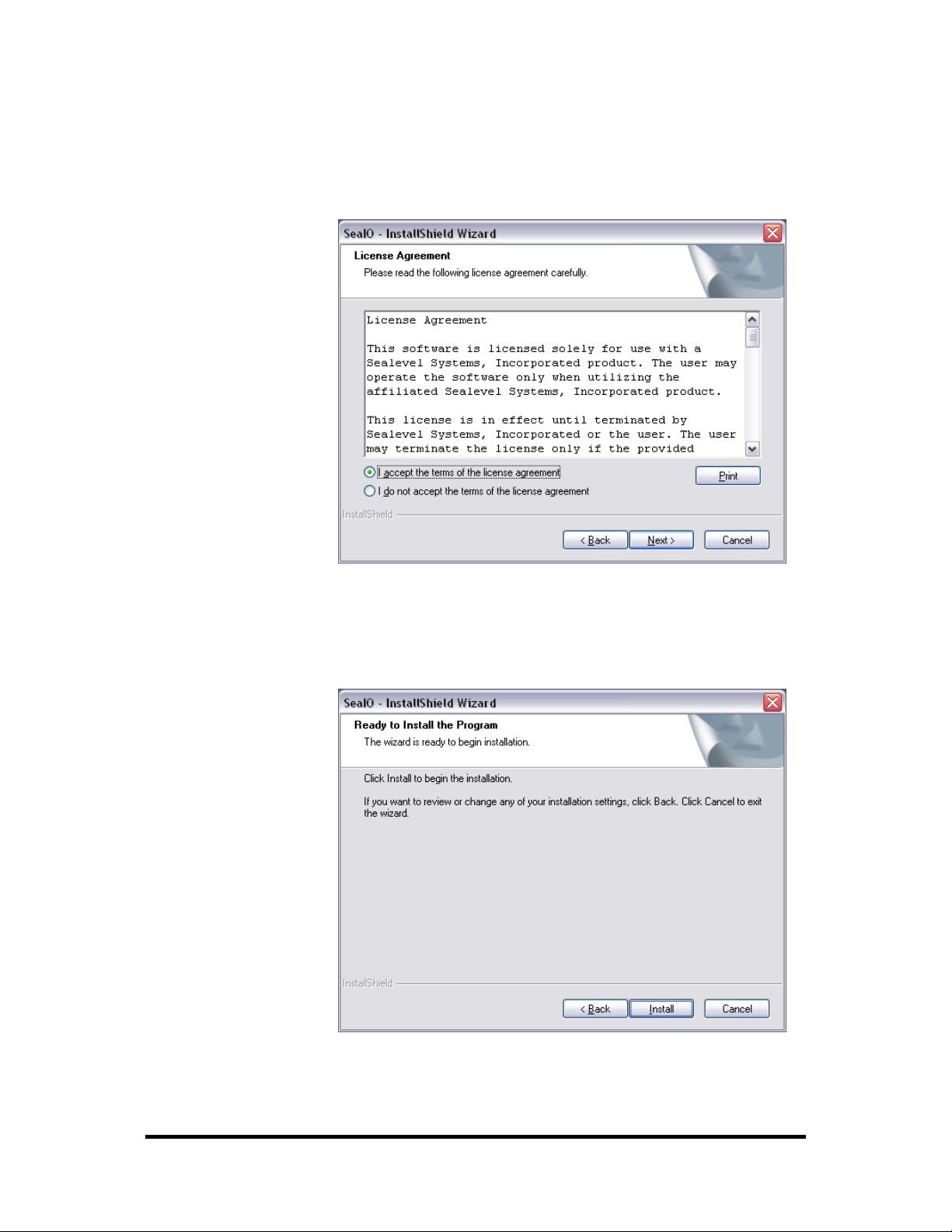
8. When the ‘License Agreement’ window appears, accept the terms and click
‘Next’ to continue. You can click the ‘Print’ button to print out a copy of the
agreement for your records. If you do not accept the terms of the agreement,
the installation will stop.
9. When the ‘Ready to Install the Program’ window appears, click the ‘Install’
button to install the software onto the hard drive of your computer. The files
will be automatically installed into the ‘C:\Program Files’ folder on your
computer.
Sealevel Systems, Inc.
- 4 -
DIO-32.PCIe User Manual
Page 7
©
Software Installation, continued
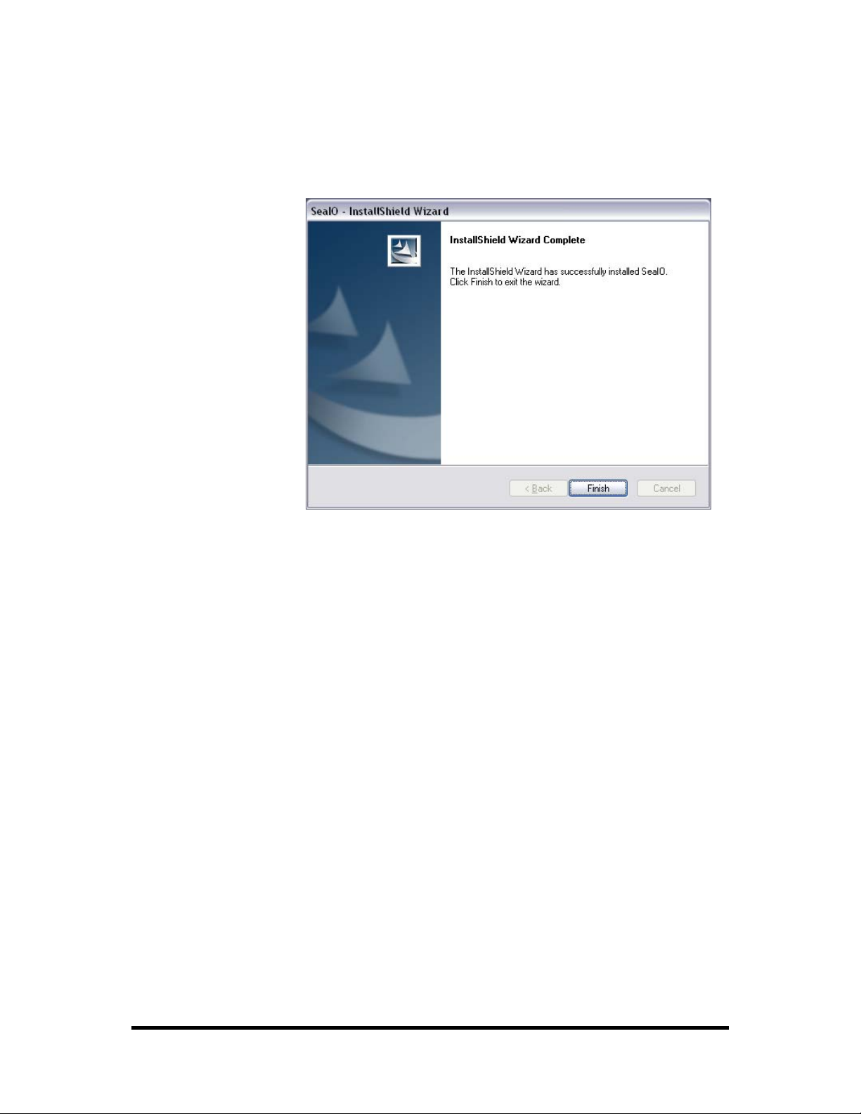
10. The setup file will automatically detect the operating environment and
install the proper components. When the ‘InstallShield Wizard Complete’
window appears, click ‘Finish’ to close the window and complete the
software installation.
11. Click the ‘X’ in the top-right corner of the ‘Product Finder’ screen to close
the CD installation window.
12. Proceed with the hardware installation of your PCI Express digital I/O
adapter.
Sealevel Systems, Inc.
- 5 -
DIO-32.PCIe User Manual
Page 8

©
Linux Installation
Licensing Information
How to Install
This package contains two components - a Linux kernel-mode device driver
and an Application Programmer's Interface. To provide the most flexible
licensing scheme, the driver is released under the GNU General Public
License version 3 while the API is released under the GNU Lesser General
Public License, also version 3. Copies of each license are located in the dox/
directory.
Modification of the configuration scripts, makefiles, or installation tools
contained in this package to support a specific platform does not constitute
creating a modified copy or a derived work.
This suite of software has been tested on Debian GNU/Linux; if you intend
to compile it on other platforms, please check the Makefile parameters
described below to ensure our software is installed to the correct locations on
your system.
In order to install the SeaIO suite, you need GNU Make (available with most
distributions) "http://www.gnu.org/software/make/". You will also need the
GCC and G++ compilers. The version is dependent on your kernel version.
The README included with your kernel source should recommend a
version known to compile properly. The SeaIO suite was developed with
GCC-2.95 on the 2.4.X kernel series and GCC-3.33 on the 2.6.X kernel
series.
You need to have compiled kernel source in /usr/src/linux, or point the KDIR
variable in the Makefile to the location of your kernel source, for the module
to compile properly. The process varies from one distribution to another and,
you should consult your distribution's particular documentation. All kernel
source obtained from http://kernel.org contains a README file detailing the
compilation process.
To install everything: simply "make install" as root from the directory where
you untarred seaio.tar.gz.
Once the kernel module is installed, running "seaioload" will create the
appropriate nodes in /dev (dio0, dio1, etc ...) Note that you will have to rerun
the "seaioload" script each time you reboot or you may add the appropriate
commands to your startup scripts.
Sealevel Systems, Inc.
- 6 -
DIO-32.PCIe User Manual
Page 9

©
Optional make commands:
Optional make parameters:
"make" or "make subdirs": this option will build all binaries, but will not
copy them to the locations described below.
"make objs": this option is similar to "make subdirs", but instead of building
executables, only objects will be created.
"make clean": this option removes all the build/executable files in the
working SeaIo directory. Installed files remain on your system.
"make uninstall": this option removes files that were previously installed to
the locations described below.
"make cleaninstall": removes any previous build files then performs a fresh
install. Everything is built from source again.
"make purge": removes installed files and build files in one command.
(exactly like performing "make uninstall" then "make clean")
(you may either manually edit them in the Makefile or pass them at run time
like so: "make install KDIR=/<PATH_TO_SOURCE>/")
KDIR= /usr/src/linux
This is the path to configured kernel source.
MODDIR= /lib/modules/<KERNEL_VERSION>/kernel/drivers/mi
sc
This is the path that the kernel module is installed to. If you modify this, you
must also modify the "seaioload" script's MODDIR variable.
SUTILDIR= /usr/local/sbin
This is the location where the "seaioload" and "seaiounload" scripts are
installed by default. You must also modify the "seaioload" script's
SUTILDIR.
UTILDIR= /usr/local/bin
This is where any standard utilities are installed.
LIBDIR= /usr/local/lib
This is where the SeaIO API library is installed. (libseaio.a)
INCLUDDIR= /usr/local/include
This is where the seaio header files will be installed.
CONFIGDIR= /etc
seaio.conf will live here. This file is consulted by "seaioload", so if you
change this, modify the CONFIGDIR variable in "seaioload".
Sealevel Systems, Inc.
- 7 -
DIO-32.PCIe User Manual
Page 10

©
Installation Steps
Note: You MUST have "root" privileges to install the software and drivers.
1. Login as "root".
2. Mount the CDROM by typing:
mount -t iso4860 /dev/hdc /cdrom
Note Your cdrom may not be /dev/hdc it could be /dev/hda, /dev/hdb, /dev/hdd, or if
you have a SCSI drive /dev/sda, /dev/sdb, /dev/sdc, etc. You may mount the
CDROM to any location, the /cdrom is just a common example.
3. Next change to the directory where you mounted the CDROM:
Ex. cd /cdrom/software/SeaIO/Other/linux
Note: The syntax is case sensitive.
4. Copy SeaIO_*.*.*.tar.gz to your home directory by typing:
cp SeaIO_*.*.*.tar.gz ~
5. Change to your home directory by typing:
cd ~
6. Unmount the drive and then Unzip and Untar the drivers and software by
typing:
umount /cdrom
tar -xvzf SeaIO_*.*.*.tar.gz
7. Change to the seaio directory by typing:
cd seaio
8. Now compile and prepare the drivers for use (this also installs binaries to
default directories):
make install
9. With the system off and unplugged, install your SeaIO PCI Express card.
10. Plug system back in and boot Linux.
Login as "root".
11. Load the driver by typing:
seaioload
The driver has enabled the card and is ready to use, and you now have the option to
run a test utility on it. Skip to section "Using the test software" if you wish to do so
at this time.
To set up Linux to automatically load the driver, refer to a Linux manual concerning
your specific distribution for help. The seaioload and seaiounload scripts are
provided as examples in the ‘scripts’ directory and are a good place to begin when
creating startup scripts.
Sealevel Systems, Inc.
- 8 -
DIO-32.PCIe User Manual
Page 11

©
Hardware Installation
Do not install the PCI Express board until the software
has been successfully installed.
The DIO-32.PCIe does not need to be configured prior to installation.
Once you have installed the SeaI/O Classic software, install the board into an
available PCI Express slot and boot the computer. The Found New Hardware wizard
will appear. The drivers that were installed during the software installation process
will automatically be used to configure the adapter.
The following instructions are applicable to the Windows XP operating system and
may vary depending on your version of Windows.
1. After the software installation is complete, install the DIO-32.PCIe into an
available PCI Express slot and boot the computer.
2. A ‘Found New Hardware’ alert will appear above the system tray.
3. When the ‘Found New Hardware Wizard’ appears, choose ‘Install the
software automatically’ and click ‘Next’ (as shown in the image below).
Sealevel Systems, Inc.
- 9 -
DIO-32.PCIe User Manual
Page 12

©
Hardware Installation, continued
4. The appropriate drivers for your digital I/O device and version of Windows
will be installed as shown.
5. Click ‘Finish’ to complete the installation of your hardware.
6. When the ‘Found New Hardware’ alert informs you that your hardware is
installed and ready to use, you can proceed with verifying the installation to
check functionality if necessary.
Sealevel Systems, Inc.
- 10 -
DIO-32.PCIe User Manual
Page 13
©
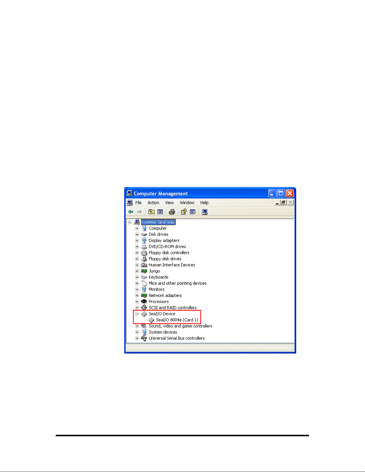
Verifying Installation
To confirm that the digital I/O card has been successfully installed and recognized
by your operating system, look in the Windows Device Manager.
To access Device Manager, follow the steps below:
1. Right click on ‘My Computer’ icon on your desktop or in the Start menu.
2. Click ‘Manage’ in the fly out menu to launch the ‘Computer Management’
3. In the left pane under ‘System Tools’, click ‘Device Manager’.
4. In right pane near the bottom, expand the ‘SeaI/O Device’ section by
5. You should see the card assignment listed as ‘SeaI/O 8004e’ with the card
console window.
clicking the ‘+’ symbol. This shows the parent device is installed correctly.
number in parentheses. The card number will increment for each additional
SeaI/O device installed.
The DIO-32.PCIe is now ready for use.
Sealevel Systems, Inc.
- 11 -
DIO-32.PCIe User Manual
Page 14

©
Programming the DIO-32.PCI
Sealevel’s SeaI/O Classic software is provided to assist in the development of
reliable applications for the Sealevel Systems family of PCI and PCI Express digital
I/O adapters. The SeaI/O Classic software is included on the CD that shipped with
the board. The software contains driver functions for use in accessing the I/O as well
as helpful samples and utilities.
Programming for Windows
The SeaI/O Classic API (Application Programmer Interface) provides a variety of
useful high-level function calls implemented in a Windows dynamic link library
(DLL). The API is defined in the help file (Start/Programs/SeaIO/SeaIO Help)
under “Application Programmers Interface”. This help file also includes detailed
information dealing with installation / removal of the software and information
about latency, logic states, and device configuration.
For C language programmers we recommend using the API to access the DIO-
32.PCI. If you are programming in Visual Basic, using the ActiveX control
included with SeaI/O is advised.
Samples and Utilities
A variety of sample programs and utilities (both executable and source code) are
included with SeaI/O. Further documentation on these samples can be found by
selecting “Start/Programs/SeaIO/Sample Application Description”. Information
about where the files are physically stored on your disk is also included in this same
file.
Programming for Linux
SeaI/O for Linux consists of two major parts: a kernel module and a library. The
kernel module is a simple IO pass-through device, allowing the library to handle the
more sophisticated functions provided to SeaI/O users. It is provided in a ‘tarball’
format and can easily be compiled and included in the kernel build.
Digital I/O Interface
The DIO-32.PCIe provides four parallel input/output (I/O) ports. The ports are
organized as ports A, B, C, and D. Port A and B are input ports interfaced to
optically-isolated inputs, while ports C and D are reed relay output ports. Assuming
an I/O address of 300 Hex the following table shows the Port Addresses.
Base Address Hex Decimal Mode
Port A Address 300 768
Port B Address 301 769
Port C Address 302 770
Port D Address 303 771
Optically Isolated Input Port
Reed Relay Output Port
Sealevel Systems, Inc.
- 12 -
DIO-32.PCIe User Manual
Page 15

©
Input Ports
Ports A and B are 8 bit input ports connected to optically isolated input sensors.
Each sensor can be used to interface a voltage input and then sense whether the
voltage is on or off. Each sensor is isolated (with respect to a common ground) from
every other sensor, and also isolated with respect to the host PC ground. This means
that signals such as low-level AC line voltage, motor servo voltage, and control
relay signals can be ‘sensed’, or read by the PC, without the risk of damage due to
ground loops or ground faults.
Each sensor input pair has a current limiting resistor that is used to limit the input
current to the opto-isolator. The opto-isolator has two ‘back-to-back’ diodes
internally. This allows AC or DC signals to be sensed, regardless of polarity. When
the applied voltage is high enough to cause the led in the opto-isolator to turn-on, the
output of the opto-isolator goes low (0 volts) and the signal is read as a low logic
level (binary 0) by the PC. When the input signal is too low to turn on the optoisolator, the output goes high and the port bit is read by the PC as a high logic level
(binary 1).
The input impedance of each isolated input is approximately 560 ohms
(factory default). The opto-isolator requires approximately 3mA to turn on. The
maximum input current is 50mA. There are two things to consider when selecting
the input resistor. The first is turn on voltage for the circuit to sense, and second is
the maximum input voltage. Maximum input voltage must not provide too much
power to the input resistor, and must also not overdrive the opto-isolator input
current specification. The following formulas apply:
Turn on Voltage = diode drop + (turn on current) x (resistance)
[Ex: 1.1 + (.003) x R]
Input Current = ((input voltage)-1.1V) / (resistor value)
Maximum voltage = 1.1 + square root of (.25(resistor value))
The following table shows common input resistors and the ranges associated with
each.
Input Resistor Turn-On Input Range Max Input Max Current
220Ω
560Ω
1KΩ
2.2KΩ
3.3KΩ
4.7KΩ
1.8V 1.8 – 7.0V 8.5V 27mA
2.8V 2.8 – 10.6V 12.9V 20mA
4.1V 4.1 – 13.8V 16.9V 15mA
7.7V 7.7 – 20.0V 24.5V 10mA
10.0V 10.0 – 24.0V 30.0V 9mA
15.2V 15.2 – 28.0V 35.0V 7mA
Note: The turn-off voltage for all resistors is less than 1V.
Increasing the input resistor accordingly can increase the maximum input voltage.
Because socketed DIP resistors are utilized, they can easily be replaced with a
different value. Sealevel, if necessary can do this.
Important: The input circuits are not intended for monitoring 120-volt AC circuits.
In addition to being too high a voltage for the circuits, it is dangerous to have that
high a voltage on the card.
Sealevel Systems, Inc.
- 13 -
DIO-32.PCIe User Manual
Page 16

©
Input Ports Pin Assignments (DB-37 Female)
Inputs are interfaced via the DB-37 female connector on the supplied CA165 cable.
Port A Bit Port A Pins Port B Bit Port B Pins
0 18,37 0 10,29
1 17,36 1 9, 28
2 16,35 2 8,27
3 15,34 3 7,26
4 14,33 4 6,25
5 13,32 5 5,24
6 12,31 6 4,23
7 11,30 7 3,22
Ground 2,20,21
+12 Volts 1
+5 Volts 19
NOTE:
The CA165 cable input pin out is not compatible with the 3093 ISA
digital I/O board. If you are upgrading from the 3093 and wish to
preserve existing infrastructure wiring, order the CA378 cable.
Output Ports (Reed Relay)
Reed relays provide very high quality, long life, low current (10 Watt maximum),
dry contact switch closures. Reed relays are not suited for high current applications,
and can be destroyed by inductive load switching, where a spark occurs across the
contacts internally. The relays are normally open, and close when energized.
Output Ports (Reed Relay) Pin Assignments (DB-37 Male)
Outputs are interfaced via the DB-37 male connector on the supplied CA165 cable.
Port C Bit Relay Port C Pins Port D Bit Relay Port D Pins
0 K16 2,20 0 K8 10,28
1 K15 3,21 1 K7 11,29
2 K14 4,22 2 K6 12,30
3 K13 5,23 3 K5 13,31
4 K12 6,24 4 K4 14,32
5 K11 7,25 5 K3 15,33
6 K10 8,26 6 K2 16,34
7 K9 9,27 7 K1 17,35
Ground 18,36,37
+ 5 Volts 19
+ 12 Volts 1
Sealevel Systems, Inc.
- 14 -
DIO-32.PCIe User Manual
Page 17

©
DB-78 Female Pin Assignments (Card Edge Connector)
Bit Port A Pins Port B Pins Port C Pins Port D Pins
0 55,74 47,66 2,20 10,28
1 54,73 46,65 3,21 11,29
2 53,72 45,64 4,22 12,30
3 52,71 44,63 5,23 13,31
4 51,70 43,62 6,24 14,32
5 50,69 42,61 7,25 15,33
6 49,68 41,60 8,26 16,34
7 48,67 40,59 9,27 17,35
GND 39,57,58 18,36,37
+12V 38 1
+5V 56 19
Direct Hardware Control
In systems where the users program has direct access to the hardware (DOS) the
tables that follow give the mapping and functions that the DIO-32.PCIe provides.
Function Available Port Address Hex Port Type
RD = Read, RD/WR = Read or Write
Reading the Inputs
The inputs are active Low. If no voltage is applied across one of the differential
inputs it returns a one on that bit. If an AC or DC voltage is applied it returns a zero
on that bit.
Reading the Outputs
The relay ports return the ones complement of the value that is currently being used
to drive the relays.
Writing the Outputs
The output ports are the only ports that can be written. The relays on a standard
DIO-32.PCIe are normally open. To close a relay a one must be written to the
appropriate bit.
RD A Base + 0
RD B Base + 1
RD/WR C Base + 2
RD/WR D Base + 3
Optically Isolated Input Port
Reed Relay Output Port
Sealevel Systems, Inc.
- 15 -
DIO-32.PCIe User Manual
Page 18

©
Register Description
All ports are set to input after reset or power up.
Address Mode D7 D6 D5 D4 D3 D2 D1 D0
Base+0
Base+1
Base+2
Base+3
Base+4
Input Port A RD PAD7 PAD6 PAD5 PAD4 PAD3 PAD2 PAD1 PAD0
Input Port B RD PBD7 PBD6 PBD5 PBD4 PBD3 PBD2 PBD1 PBD0
Output Port C RD/WR PCD7 PCD6 PCD5 PCD4 PCD3 PCD2 PCD1 PCD0
Output Port D RD/WR PDD7 PDD6 PDD5 PDD4 PDD3 PDD2 PDD1 PDD0
RD 0 0 0 0 0 0 0 0
Sealevel Systems, Inc.
- 16 -
DIO-32.PCIe User Manual
Page 19

©
Optional 3093 Migration Cable (CA378)
On the 3093 ISA digital I/O board, the input pins #1 and #19 are reversed from the
standard CA165 cable that ships standard with the 8004. If you are upgrading from a
3093 ISA board to an 8004 PCI board and wish to preserve existing infrastructure
wiring, order the CA378 cable and use it in place of the standard CA165 cable.
CA378 Input Pin Assignments (DB-37 Female)
Inputs are interfaced via the DB-37 female connector on the optional CA378 cable.
Port A Bit Port A Pins Port B Bit Port B Pins
0 18,37 0 10,29
1 17,36 1 9, 28
2 16,35 2 8,27
3 15,34 3 7,26
4 14,33 4 6,25
5 13,32 5 5,24
6 12,31 6 4,23
7 11,30 7 3,22
Ground 2,20,21
+12 Volts 19
+5 Volts 1
NOTE:
The CA378 cable is designed specifically for customers upgrading
from a 3093 ISA board to the 8004 PCI board. If you are not
upgrading from the 3093 board, use the standard CA165 cable that
ships with the 8004 PCI digital I/O board.
CA378 Output Pin Assignments (DB-37 Male)
Outputs are interfaced via the DB-37 male connector on the optional CA378 cable.
Port C Bit Relay Port C Pins Port D Bit Relay Port D Pins
0 K16 2,20 0 K8 10,28
1 K15 3,21 1 K7 11,29
2 K14 4,22 2 K6 12,30
3 K13 5,23 3 K5 13,31
4 K12 6,24 4 K4 14,32
5 K11 7,25 5 K3 15,33
6 K10 8,26 6 K2 16,34
7 K9 9,27 7 K1 17,35
Ground 18,36,37
+ 5 Volts 19
+ 12 Volts 1
Sealevel Systems, Inc.
- 17 -
DIO-32.PCIe User Manual
Page 20

©
Electrical Characteristics
Features
2 sets SPST relays with each having 8 relays
2 eight bit input ports
DB-37 Male connector for relay outputs
DB-37 Female connector for optically isolated inputs
Highly reliable 10 VA DIP reed relays
Multiple adapters can reside in same computer
Specifications
Input Ports
Turn On Current: 3mA
Isolator Diode Drop: 1.1 VDC
Resistor Power Max: .25 W
Maximum Input Range: 3 – 13 VDC/VAC
Maximum Input Current: 50mA
Output Relays
Contact Max Power Rating: 10 W
Contact Voltage Maximum: 100 VDC/VAC
Contact Current Maximum: .5A AC/DC RMS
Contact Resistance, Initial: .15 Ω
Rated Life:
• Low Load: 200 Million Closures
• Maximum Load: 100 Million Closures
Contact Speed:
• Operate: .5 mS
• Release: .5 mS
• Bounce: .5 mS
Maximum Operating Speed: 600 Hz
Temperature Range
Operating: 0°C – 70°C
Storage: -50°C – 105°C
Physical Dimensions
PCB Length: 6.5” (16.5 cm)
PCB Height: 4.2” (10.7 cm)
Manufacturing
All Sealevel Systems Printed Circuit boards are built to UL 94V0 rating and are
100% electrically tested. These printed circuit boards are solder mask over bare
copper or solder mask over tin nickel.
Sealevel Systems, Inc.
- 18 -
DIO-32.PCIe User Manual
Page 21

©
Example Circuits
Input Circuit
Output Circuit
Sealevel Systems, Inc.
- 19 -
DIO-32.PCIe User Manual
Page 22

©
Appendix A - Troubleshooting
Following these simple steps can eliminate most common problems.
1. Install software first. After installing the software then proceed to adding the
hardware. This places the required installation files in the correct locations.
2. Read this manual thoroughly before attempting to install the adapter in your
system.
3. Use Device Manager under Windows to verify proper installation. Refer to the
Verifying Hardware section of this manual for instructions.
4. Several utilities with source code are included to verify the functionality of the
inputs and outputs and to aid in application development. To test the inputs, you
need to supply the turn-on voltage with a minimum of 3mA (maximum input
current is 50mA) to trigger an input. Consult the pin out diagrams to test at the
card edge connector or at the end of the cable.
5. Use the VCTest to verify the basic I/O functionality of your digital I/O board.
The source code is included to simplify application development in the
programming language C.
Sealevel Systems, Inc.
- 20 -
DIO-32.PCIe User Manual
Page 23

©
6. VBTest is another utility included with SeaI/O Classic software. The source
code is included to aid with Visual Basic application development.
Sealevel Systems, Inc.
- 21 -
DIO-32.PCIe User Manual
Page 24

©
7. SeaIOTST is a command line utility that allows you to test the function calls
from the SeaI/O Classic API.
Notes:
The source code for all utilities is located in the following folder:
C:\Program Files\SeaIO\Samples
The API is documented in the SeaIO help file. Start Æ All Programs Æ SeaIO Æ
SeaIO Help. Launch the help file and expand the Programmers Interface section.
If these steps do not solve your problem, please call Sealevel Systems’ Technical
Support, (864) 843-4343. Our technical support is free and available from 8:00AM5:00PM Eastern Time Monday through Friday. For email support contact
support@sealevel.com
.
Sealevel Systems, Inc.
- 22 -
DIO-32.PCIe User Manual
Page 25

©
Appendix B - How To Get Assistance
Begin by reading through the Trouble Shooting Guide in Appendix A. If assistance
is still needed please see below.
When calling for technical assistance, please have your user manual and current
adapter settings. If possible, please have the adapter installed in a computer ready to
run diagnostics.
Sealevel Systems provides an FAQ section on its web site. Please refer to this to
answer many common questions. This section can be found at
http://www.sealevel.com/faq.asp
Sealevel Systems maintains a Home page on the Internet. Our home page address is
http://www.sealevel.com
. The latest software updates, and newest manuals are
available via our FTP site that can be accessed from our home page.
Technical support is available Monday to Friday from 8:00 a.m. to 5:00 p.m. eastern
time. Technical support can be reached at (864) 843-4343.
RETURN AUTHORIZATION MUST BE OBTAINED FROM SEALEVEL
SYSTEMS BEFORE RETURNED MERCHANDISE WILL BE ACCEPTED.
AUTHORIZATION CAN BE OBTAINED BY CALLING SEALEVEL
SYSTEMS AND REQUESTING A RETURN MERCHANDISE
AUTHORIZATION (RMA) NUMBER.
Sealevel Systems, Inc.
- 23 -
DIO-32.PCIe User Manual
Page 26

©
Appendix C – Silk Screen – 8004e PCB
Sealevel Systems, Inc.
- 24 -
DIO-32.PCIe User Manual
Page 27

©
Appendix D - Compliance Notices
Federal Communications Commission Statement
FCC - This equipment has been tested and found to comply with the limits for Class
A digital device, pursuant to Part 15 of the FCC Rules. These limits are designed to
provide reasonable protection against harmful interference when the equipment is
operated in a commercial environment. This equipment generates, uses, and can
radiate radio frequency energy and, if not installed and used in accordance with the
instruction manual, may cause harmful interference to radio communications.
Operation of this equipment in a residential area is likely to cause harmful
interference in such case the user will be required to correct the interference at the
users expense.
EMC Directive Statement
Products bearing the CE Label fulfill the requirements of the EMC directive
(89/336/EEC) and of the low-voltage directive (73/23/EEC) issued by the European
Commission.
To obey these directives, the following European standards must be met:
EN55022 Class A - “Limits and methods of measurement of radio interference
characteristics of information technology equipment”
EN55024 – “Information technology equipment Immunity characteristics Limits and
methods of measurement”.
EN60950 (IEC950) - “Safety of information technology equipment, including
electrical business equipment”
Warning
This is a Class A Product. In a domestic environment, this product may cause
radio interference in which case the user may be required to take adequate
measures to prevent or correct the interference.
Always use cabling provided with this product if possible. If no cable is provided or
if an alternate cable is required, use high quality shielded cabling to maintain
compliance with FCC/EMC directives.
Sealevel Systems, Inc.
- 25 -
DIO-32.PCIe User Manual
Page 28

©
Warranty
Sealevel's commitment to providing the best I/O solutions is reflected in the Lifetime
Warranty that is standard on all Sealevel manufactured products. We are able to
offer this warranty due to our control of manufacturing quality and the historically
high reliability of our products in the field. Sealevel products are designed and
manufactured at its Liberty, South Carolina facility, allowing direct control over
product development, production, burn-in and testing.
Sealevel Systems, Inc. (hereafter "Sealevel") warrants that the Product shall conform
to and perform in accordance with published technical specifications and shall be
free of defects in materials and workmanship for life. In the event of failure,
Sealevel will repair or replace the product at Sealevel's sole discretion. Failures
resulting from misapplication or misuse of the Product, failure to adhere to any
specifications or instructions, or failure resulting from neglect or abuse are not
covered under this warranty.
Warranty service is obtained by delivering the Product to Sealevel and providing
proof of purchase. Return authorization must be obtained from Sealevel Systems
before returned merchandise will be accepted. Authorization is obtained by
calling Sealevel Systems and requesting a Return Merchandise Authorization
(RMA) number. The Customer agrees to insure the Product or assume the risk of
loss or damage in transit, to prepay shipping charges to Sealevel, and to use the
original shipping container or equivalent. Warranty is valid only for original
purchaser and is not transferable.
Trademarks
Sealevel Systems assumes no liability for any damages, lost profits, lost savings or
any other incidental or consequential damage resulting from the use, misuse of, or
inability to use this product. Sealevel Systems will not be liable for any claim made
by any other related party.
This warranty applies to Sealevel manufactured Product. Product purchased through
Sealevel but manufactured by a third party will retain the original manufacturer's
warranty.
Sealevel Systems, Incorporated
2779 Greenville Highway
P.O. Box 830
Liberty, SC 24857 USA
(864) 843-4343 FAX: (864) 843-3067
www.sealevel.com
email: support@sealevel.com
Technical Support is available Monday - Friday from 8 a.m. to 5 p.m. Eastern time
Sealevel Systems, Incorporated acknowledges that all trademarks referenced in this
manual are the service mark, trademark, or registered trademark of the respective
company.
Sealevel Systems, Inc.
- 26 -
DIO-32.PCIe User Manual
 Loading...