

Page 1
Sealevel Systems, Inc.
Sealevel.com
Phone 864.843.4343
Page 2

©Sealevel Systems, Inc.
SL9219 - 06/2011
7804e Manual
2
INTRODUCTION ............................................................................................... 3
BEFORE YOU GET STARTED ................................................................................ 4
CARD SETUP .................................................................................................. 6
SOFTWARE INSTALLATION .................................................................................. 9
Option 1: Using the setserial command line utility. ................................................. 15
Option 2: Modify 8250 driver to include Sealevel Product/Vendor IDs. ................. 16
TECHNICAL DESCRIPTION ................................................................................ 18
SPECIFICATIONS ............................................................................................ 21
APPENDIX A - TROUBLESHOOTING ...................................................................... 22
APPENDIX B - HANDLING INSTRUCTIONS .............................................................. 23
Electrostatic Discharges (ESD) ..................................................................................... 23
APPENDIX C - ELECTRICAL INTERFACE ................................................................. 24
APPENDIX D - ASYNCHRONOUS COMMUNICATIONS ................................................. 26
APPENDIX E – MECHANICAL DRAWING ................................................................. 27
WARRANTY .................................................................................................. 28
Page 3

©Sealevel Systems, Inc.
SL9219 - 06/2011
7804e Manual
3
The Sealevel Ultra COMM+8.PCIe is an eight channel RS-232/485/422 PCI express Bus serial I/O
adapter supporting data rates up to 921.6Kbps.
The RS-232 compatibility allows for connection to devices utilizing the RS-232 electrical
interface, such as modems, data-entry terminals, and plotters.
RS-422 provides excellent communications for long distance device connections up to 4000ft.,
where noise immunity and high data integrity are essential.
RS-485 is optimized for „Multi-Drop‟ or „Party-line‟ operations selecting data from multiple
peripherals (as many as 31 devices can be connected on an RS-485 bus).
In both RS-485 and RS-422 modes, the card works seamlessly with the standard operating
system serial driver. In RS-485 mode, our special auto-enable feature allows the RS-485 ports to
be viewed by the operating system as a COM: port. This allows the standard COM: driver to be
utilized for RS-485 communications. Our on-board hardware automatically handles the RS-485
driver enable.
The Ultra COMM+8.PCIe will operate on x1, x4, x8 or x16 PCIe bus slots.
Each port individually configurable for RS-232, RS-422, or RS-485
16C954 buffered UARTs with 128-byte FIFOs
Oscillator and clock prescalar support wide range of baud rates
Supports 9-bit protocol framing
Each port supports data rates to 921.6K bps
RS-485 line termination, pull-up and pull-down resistors for each port are selectable via
dipswitch
RS-485 ECHO can be enabled/disabled via
dipswitch
PCI Express X1 compliant
Compatible with all standard size PCI Express
slots
All modem control signals implemented in RS-
232 mode
Automatic RS-485 enable/disable in hardware
Included 36" cable terminates to eight DB9M connectors (Item# CA145)
Page 4
©Sealevel Systems, Inc.
SL9219 - 06/2011
7804e Manual
4
The Ultra COMM=8.PCIe is shipped with the following items. If any of these items are missing or
damaged, please contact Sealevel for replacement.
Ultra COMM+8.PCIe Serial I/O Adapter
CA145
Sealevel Software CD
Warning - The highest level of importance used to stress a condition where damage
could result to the product or the user could suffer serious injury.
Important – The middle level of importance used to highlight information that might
not seem obvious or a situation that could cause the product to fail.
Note – The lowest level of importance used to provide background information,
additional tips, or other non-critical facts that will not affect the use of the product.
Page 5
©Sealevel Systems, Inc.
SL9219 - 06/2011
7804e Manual
5
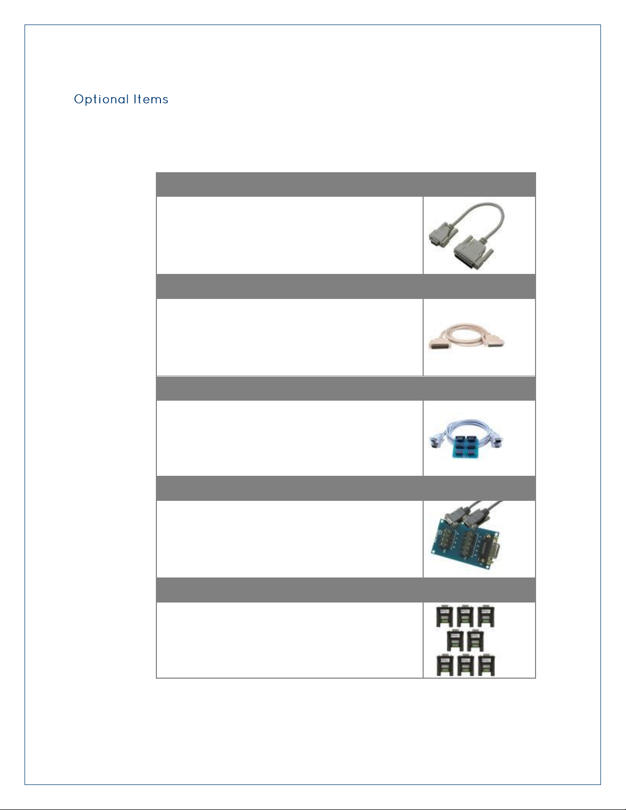
DB9 to DB25 Serial Cable (Item# CA176)
DB9 Female (RS-422) to DB25 Male (RS-530) Cable, 10 in
Length
DB78 Extension Cable (Item# CA233)
DB78 Male to DB78 Female, 72 in Length - Extension
Cable
Terminal Block Kit (Item# KT106)
Terminal Block Kit - TB06 + (2) CA127 Cables
Terminal Block Kit (Item# KT105)
Terminal Block Kit - TB05 + CA127 Cable
Terminal Block Kit (Item# TB34-8)
Terminal Block Kit (8 Pack) - DB9 Female to 5 Screw
Terminals (RS-422/485)
Depending upon your application, you are likely to find one or more of the following items
useful with the Ultra COMM+8.PCIe. All items can be purchased from our website
(www.sealevel.com) by calling our sales team at (864) 843-4343.
Page 6
©Sealevel Systems, Inc.
SL9219 - 06/2011
7804e Manual
6
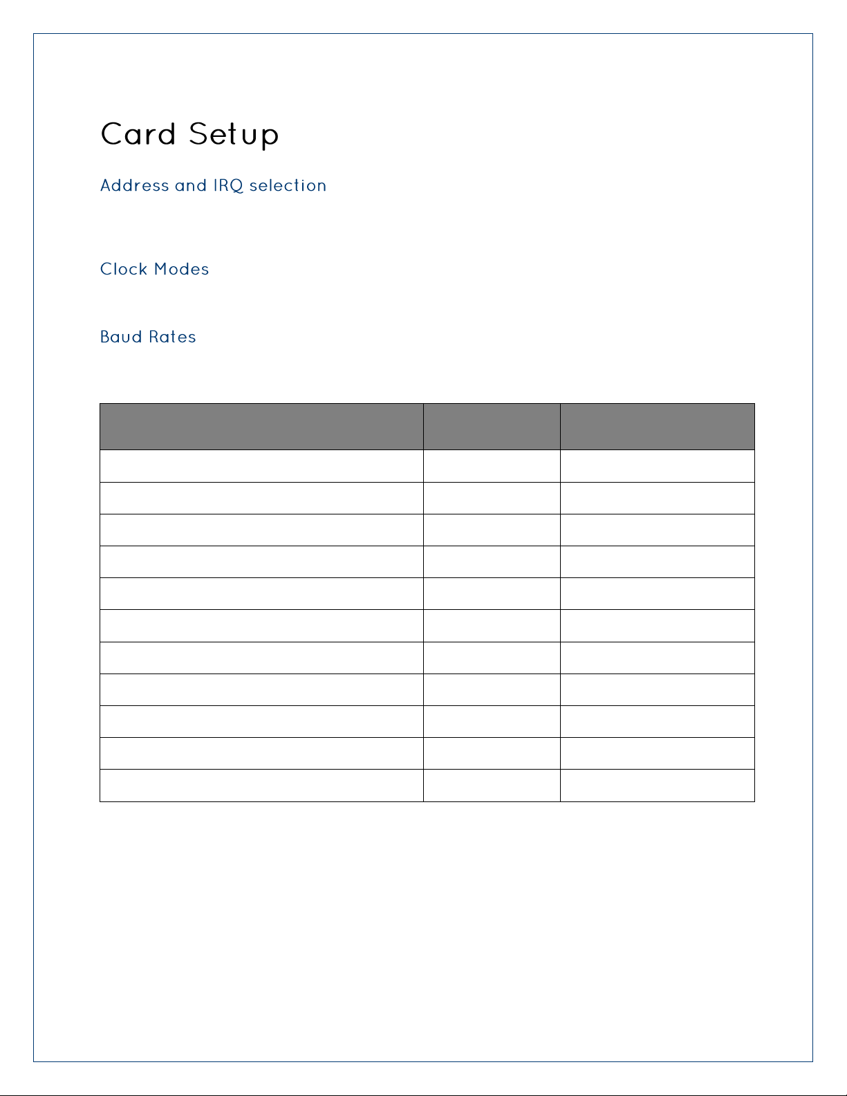
For This Data Rate
CPR
Choose This Divisor
DLM:DLL
1200 bps
32
3254
2400 bps
32
1627
4800 bps
32
813
9600 bps
32
406
19.2K bps
32
203
38.4K bps
32
102
57.6K bps
32
68
115.2K bps
32
34
230.4K bps
32
17
460.8K bps
8
34
921.6K bps
8
17
The Ultra COMM+8.PCIe is automatically assigned I/O addresses and IRQs by your motherboard
BIOS or by a „Plug-n-Play‟ Operating System. Adding or removing other hardware or moving the
adapter to another slot may change the assignment of I/O addresses and IRQs.
The Ultra COMM+8.PCIe derives a 62.5MHz clock from the PCI express link which is divided by
a 8 bit clock prescaler and a 16 bit clock divisor to provide a wide range of possible baud rates.
The following table shows some common data rates and the rates you should choose to achieve
them when using the ULTRA COMM+8.PCI
Page 7
©Sealevel Systems, Inc.
SL9219 - 06/2011
7804e Manual
7
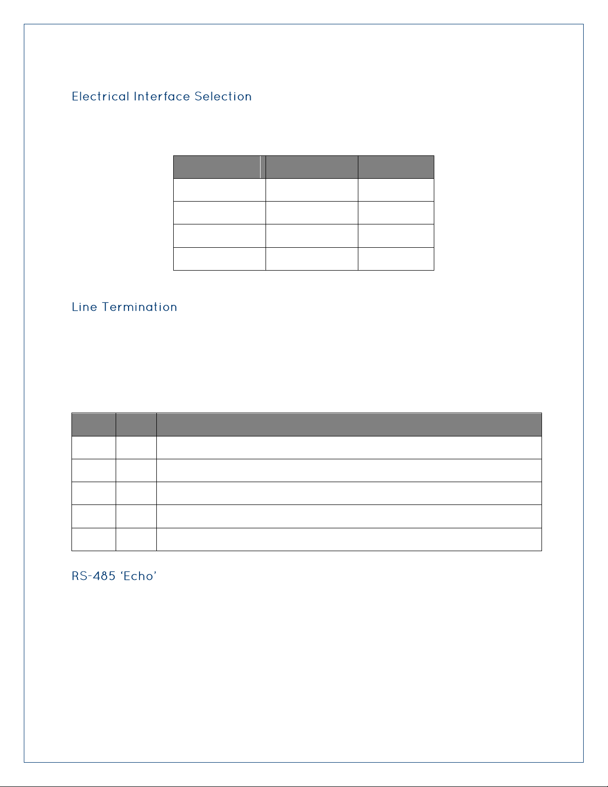
Switch 1 (Silk M1)
Switch 2 (Silk M0)
Mode Select
OFF
OFF
232
OFF
ON
422
ON
OFF
485 With Echo
ON
ON
485 No Echo
Switch
Name
Function
3
T
Adds or removes the 120 ohm termination.
4
PU
Adds or removes the 1K ohm pull-up resistor in the RS-422/RS-485 receiver circuit
5
PD
Adds or removes the 1K ohm pull-down resistor in the RS-422/RS-485 receiver circuit
6
L
Connects the TX- to RX- for RS-485 two-wire operation.
7
L
Connects the TX+ to RX+ for RS-485 two-wire operation.
Each of the eight ports on the ULTRACOMM+8.PCI can be individually configured as an RS-232,
RS-422, or RS-485 interface. This is selectable via the port DIP-switch, each is labeled with its
port number.
Typically, each end of the RS-485 bus must have line-terminating resistors (RS-422 terminates
at the receive end only). A 120-ohm resistor is across each RS-422/485 input in addition to a
1K-ohm pull-up/pull-down combination that biases the receiver inputs. Each switch allows
customization of this interface to specific requirements. Each switch position corresponds to a
specific portion of the interface. If multiple Ultra COMM+8.PCIe adapters are configured in an
RS-485 network, only the boards on each end should have switches T, P & P ON. Refer to the
following table for each position‟s operation:
The RS-485 „Echo‟ is the result of connecting the receiver inputs to the transmitter outputs.
Every time a character is transmitted; it is also received. This can be beneficial if the software
can handle echoing (i.e. using received characters to throttle the transmitter) or it can confuse
the system if the software does not. An RS-485 „No Echo‟ option is selected by placing both
Mode switches (M0, M1) in the „On‟ position.
Page 8
©Sealevel Systems, Inc.
SL9219 - 06/2011
7804e Manual
8
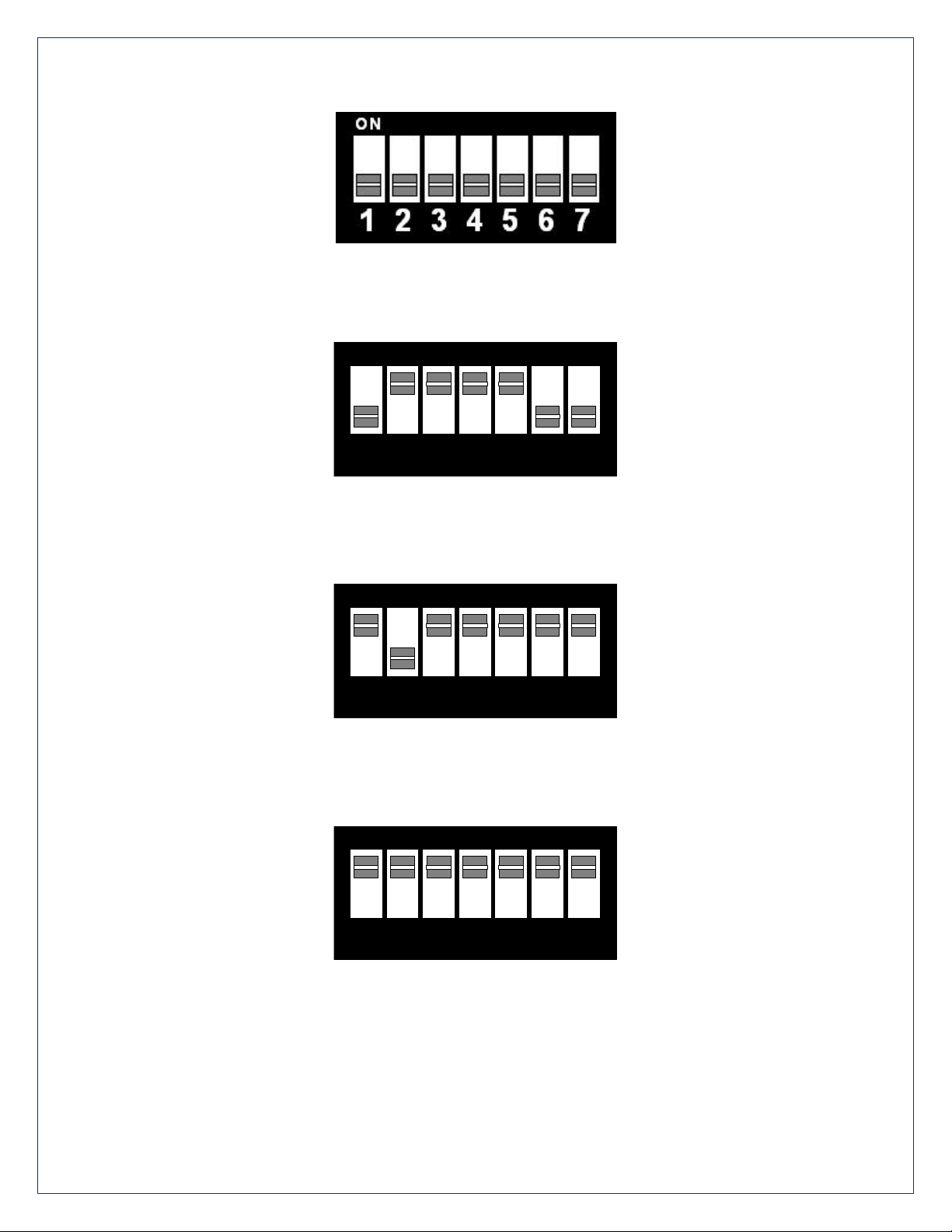
1 2 3 4 5 6 7
ON
1 2 3 4 5 6 7
ON
1 2 3 4 5 6 7
ON
Figure 1 - RS-232 Mode
Figure 2 - RS-422 Mode
Figure 3 - RS-485 with 'Echo'
Figure 4 - RS-485 No 'Echo'
Page 9
©Sealevel Systems, Inc.
SL9219 - 06/2011
7804e Manual
9
This section contains helpful information pertaining to the installation of supported Sealevel
Systems, Inc. software packages. First, the process of acquiring the software is discussed.
Next, the installation is detailed in a step-by-step guide for Windows and Linux operating
systems.
All Sealevel products are shipped with media containing the installers for each software
package available. If the media is otherwise unavailable or if desired, the current versions of
Sealevel software packages can be obtained from the Sealevel website (see following
instructions). If you already have the Sealevel software, proceed to the Windows or Linux
installation section.
Sealevel software for Windows and Linux operating systems is available at these links:
o Software for Windows
o Software for Linux
Choose the link for the desired software package and click on the „Download File‟ link to
download the current driver.
Proceed to the Manual Software Installation guide for your operating system.
Do not connect the hardware until the software has been successfully installed.
To install Sealevel software, you must log in as an administrator or have administrator
privileges in Windows.
Page 10

©Sealevel Systems, Inc.
SL9219 - 06/2011
7804e Manual
10
1. Insert the Sealevel media into your PC.
2. If the „AutoRun‟ feature is enabled for this media the software will automatically
launch.
3. Otherwise, navigate to the root directory of the media and double-click the
„autorun.exe‟ application to launch the installation window.
4. Select „Install‟ as demonstrated in the image below.
Page 11

©Sealevel Systems, Inc.
SL9219 - 06/2011
7804e Manual
11
5. Type the part number for your adapter in the text box and press the „Enter‟ key,
or click on the drop box to scroll from the listing to select your product.
If you installed your hardware prior to loading/installing the software, please click on
the „Click here if you installed hardware before software‟ link and follow the listed
instructions.
6. Click the „Install Drivers‟ button to launch the Installation Wizard.
7. When the InstallShield Wizard‟ window appears, click the „Next‟ button to initiate
the software installation.
8. When the „License Agreement‟ window appears, accept the terms and click „Next‟
to continue. You can click the „Print‟ button to print out a copy of the agreement
for your records. If you do not accept the terms of the agreement, the
installation will stop.
9. When the „Ready to Install the Program‟ window appears, click the „Install‟ button
to install the software onto the hard drive of your computer. The files will be
automatically installed into the „C:\Program Files‟ folder on your computer.
Some versions of Windows will halt the installation and provide you with a dialog
box which will ask you for permission for the installer to make changes to your
computer. Click on the „Allow‟ button to continue installation of your Sealevel
Page 12

©Sealevel Systems, Inc.
SL9219 - 06/2011
7804e Manual
12
software.
10. The following dialog box may appear, as shown below. Click the „OK‟ button to
continue.
All Sealevel Systems software drivers have been fully tested by Sealevel. Clicking „OK‟
will not harm your system.
11. The following dialog box may appear, as shown below. Click the „OK‟ button to
continue.
This is a notification that if you are upgrading from a previous driver version, you
should remove the associated Device Manager hardware entries and reinstall the adapter
after the installing the SeaCOM software.
12. The setup file will automatically detect the operating environment and install the
proper components. Next follow the information presented on the screens that
follow. Once the installation is complete, close the disk installation window.
13. Refer to the Physical Installation section to connect and install your adapter.
Page 13

©Sealevel Systems, Inc.
SL9219 - 06/2011
7804e Manual
13
1. To install a software package from the Sealevel media, browse the Sealevel Systems
media ‟Software‟ directory. For example: Software\SeaIO\Windows\SeaIO
Installer.exe
2. If you are using Windows Vista or newer operating systems, right click on the
installer executable and choose ‟Run as Administrator‟. If you are using an operating
system prior to Windows Vista, double click on the executable to launch the
InstallShield and initiate the driver installation.
3. Please refer to step six above in the Guided Software Installation section and follow
the remaining installation steps.
1. Download the current driver using the Instructions from the Where to Get Software
section above. Please take note of the destination directory it will save to.
2. Uninstall the currently loaded driver SeaCOM driver found in the Control Panel. Prior
to Windows Vista SeaCOM will be populated in „Add/Remove Programs‟ list. In Vista
and newer OSs it will be found in the „Programs and Features‟ list.
3. Navigate to the Device Manager and remove the Sealevel adapter by right clicking on
the line item choosing „Uninstall‟. Depending on your product, it can be found under
either „Multiport Serial adapters‟ or „Universal Serial Bus controllers‟.
4. Single port ISA cards and PCMCIA cards will need to be uninstalled under „Ports
(COM & LPT)‟.
5. In the Device Manager under „Action‟, choose „Scan for Hardware changes‟. This will
prompt the installation of the adapter and associate it with the newly installed
SeaCOM driver.
Page 14

©Sealevel Systems, Inc.
SL9219 - 06/2011
7804e Manual
14
Most Sealevel Linux software is distributed as source code. To use the software, it must
be compiled. Refer to the README file in each package for system prerequisites.
You must have administrative privileges to install the software. It is not necessary to
have administrative privileges to build or use the software.
All command syntax is case sensitive.
1. Insert the Sealevel media into your PC.
2. If your desktop environment does not auto-mount the media, you will need to do so
manually using the mount command. You may need administrative privileges for
the mount command to succeed.
3. Next change to the Sealevel media directory. For example, if the mount point of
your optical drive is /cdrom:
$ cd /cdrom/Software/SeaCOM/Linux
4. Copy [package name].tar.gz to your home directory by typing:
$ cp seacom_X.Y.Z.tar.gz ~
5. Change to your home directory by typing:
$ cd
6. Extract the software from the compressed archive by using:
$ tar -zxvf seacom_X.Y.Z.tar.gz
7. Change to the package directory by typing:
$ cd seacom
8. Compile the software from source by typing:
$ make
9. Elevate permission level by changing to root:
$ su
Or use the „super user do‟ command:
$ sudo –s
10. Install the software by typing:
$ make install
Page 15

©Sealevel Systems, Inc.
SL9219 - 06/2011
7804e Manual
15
Linux already supports the direct use of 16CXXX UART based devices with drivers included in
the kernel sources. Some of Sealevel's async serial devices do not currently have their
vendor/product IDs included in this driver. It is necessary to either manually identify the UARTs
to the driver or to modify the driver by adding the vendor/product IDs.
This procedure is the ONLY method of accessing a PC/104 or ISA device by using
standard device drivers.
Since the <IO_ADDRESS> and <IRQ_NUMBER> are static in the case of PC/104 and ISA, a
distribution's start-up scripts can easily be modified to enable driver attachment (this
assumes that no new plug-and-play serial devices will be added later on, as they will be
overwritten until the start-up scripts are modified).
A recent change in the way the serial driver attaches to <MINOR> numbers may prevent
more than 4 to 32 serial ports to be attached to the driver at any time. If the total
number of required ports in the system is more than 4 and less than 32, setting the
kernel boot parameter 8250.nr_uarts=n increases the number of ports appropriately,
and this Option 1 is still viable. If the number of required ports is greater than 32, the
compiled kernel configuration parameter CONFIG_SERIAL_8250_NR_UARTS can be
changed so that it is updated when the kernel is recompiled. This means if this is a PCI
device, it may be prudent to go ahead and enable Plug-and-Play capability.
The setserial program is an open source utility to aide in the configuration of the 8250
async serial port driver. It is included with most Linux distributions or available through
that distributions package management system (check distribution documentation).
Alternatively the source code can be found at the project's website.
Once the setserial utility is available, it is necessary to determine the IO addresses and IRQ
line for each of the devices UARTs. If this is an ISA or PC/104 device, these options are
configured manually with jumpers on the board. If this is a PCI, PCI Express, or PC/104+
device, these are assigned through a combination of BIOS and OS. To determine what IO
address and IRQ line has been assigned, use the lspci command as demonstrated. The d
switch filters results to any devices with IDs VENDOR:PRODUCT. By leaving the PRODUCT ID
blank, ALL Sealevel devices attached to the PCI bus will be displayed. The vvv option tells
the command to be as verbose as possible giving us all the information we will need.
$ lspci -d 135e: -vvv
00:0f.0 Serial controller: Sealevel Systems Inc Unknown device 7203
(rev 01) (prog-if 02 16550])
Subsystem: Sealevel Systems Inc Unknown device 7203
Flags: medium devsel, IRQ 11
Memory at ee000000 (32-bit, non-prefetchable) [size=128]
I/O ports at b000 [size=128]
I/O ports at a800 [size=8]
I/O ports at a400 [size=8]
00:11.0 Serial controller: Sealevel Systems Inc Unknown device
7803 (rev 01) (prog-if 02 16550])
Subsystem: Sealevel Systems Inc Unknown device 7803
Flags: medium devsel, IRQ 10
Page 16

©Sealevel Systems, Inc.
SL9219 - 06/2011
7804e Manual
16
Memory at ed800000 (32-bit, non-prefetchable) [size=128]
I/O ports at a000 [size=128]
I/O ports at 9800 [size=64]
The <IRQ_NUMBER> can easily be extracted from the output of the lspci command. Next to
each device is listed the assigned IRQ. This is one of the two pieces of information we need!
The next piece of information can be extracted from the PCI Regions listed in the lspci
output. Each PCI device is a little different and a certain amount of thinking must be done
to determine which region(s) are mapped to the devices UARTs.
Most Sealevel devices with 4 or less ports use individual PCI regions to map each UART's
8 IO registers. So look for IO regions that have sizes of 8. There should be X number of
size 8 regions (where X is the number of UARTS on the device).
Many newer devices and 16 port devices use one large PCI region to map all of a devices
UARTs IO registers. So look for IO regions that have sizes of the product of the number
of UARTs and 8.
This information is usually contained within the device manual, but sometimes it is not.
If you are unable to determine the correct IO space, please contact Sealevel's Technical
Support for aid.
Once you know which region(s) correspond to which UARTs, you are interested in the
<IO_ADDRESS>. This is a 4-digit hexadecimal number.
Now that all the necessary information has been gathered, it is time to use the setserial
utility to attach a device to the 8250 driver. Each UART must be assigned, one at a time,
using setserial.
# setserial /dev/ttyS# port <IO_ADDRESS> irq <IRQ_NUMBER> baud_base
X
The baud_base parameter is very, very important. Without a value > 0, the setserial
command will fail. The proper baud_base is dependent on the particular piece of
hardware being used. The product manual should be consulted to identifiy the proper
baud_base.
The /dev/ttyS# (where # is an integer) must correspond to an existing device file. If there
aren't enough device files, they can be created with the following command. The <MAJOR>
is determined by the 8250 driver, and the <MINOR> is the next incremental integer. ($ ls -al
/dev/ttyS#-1 to see what they should be)
# mknod /dev/ttyS# c <MAJOR> <MINOR>
This method requires kernel sources (NOT HEADERS). These can usually be obtained
through the distribution's package management system. Alternatively the vanilla kernel
sources can be downloaded from kernel.org. Recompiling the Linux kernel goes beyond
the scope of this document, and may be different depending on the distribution used.
Consult the distribution's documentation concerning module building.
Page 17

©Sealevel Systems, Inc.
SL9219 - 06/2011
7804e Manual
17
This method could also be necessary if more than 4 8250 serial ports must be used at
the same time. This requires modifying the kernel's configuration to support more
ports.
Navigate to the directory containing kernel sources (usually /usr/src/linux).
First verify that the desired device is not already supported by the 8250 driver. Open the
header file pci_ids.h located in the include/linux subdirectory. Find the keyword
"SEALEVEL". There will be a list of definitions assigning macro names like
"PCI_DEVICE_ID_SEALEVEL_*" to hexadecimal Sealevel product IDs. Scan through the list
looking for your device's product number. If it is listed, then that device is already
supported by the 8250 driver. If it is not listed, make a new entry with a unique macro
name and the corresponding product ID.
.../include/linux/pci_ids.h
#define PCI_DEVICE_ID_SEALEVEL_COMM8 0x7801 //existing entry
#define PCI_DEVICE_ID_SEALEVEL_UCOMM8 0x7804 //new entry
Next add the device to the 8250's device detection code. Edit the 8250_pci.c file located in
the drivers/serial/ subdirectory. Again, find the keyword "SEALEVEL". There will be an array
of pci_device structs. Scroll to the last entry with a SEALEVEL vendor macro. Make a new
entry using the product ID that was created in the previous step. The last element of this
entry will be a descriptor to a specific board configuration which is hardware dependent.
Contact engineering for exact instructions to add a specific product's configuration.
.../drivers/serial/8250_pci.c
{PCI_VENDOR_ID_SEALEVEL, PCI_DEVICE_ID_SEALEVEL_COMM8, PCI_ANY_ID,
PCI_ANY_ID, 0, 0, pbn_b2_8_115200 },
{PCI_VENDOR_ID_SEALEVEL, PCI_DEVICE_ID_SEALEVEL_UCOMM8,
PCI_ANY_ID, PCI_ANY_ID, 0, 0, pbn_b2_8_115200 },
Next verify that a reasonable number of 8250 serial ports can be allocated by the device
driver. Edit the .config file located in the root of the kernel source directory. Search for the
keyword "CONFIG_SERIAL_8250". And verify that appropriate values are used for each
variable.
.../.config
CONFIG_SERIAL_8250_NR_UARTS=48
CONFIG_SERIAL_8250_RUNTIME_UARTS=48
Now recompile the driver module, remove the old module, and insert the new one.
Page 18

©Sealevel Systems, Inc.
SL9219 - 06/2011
7804e Manual
18
The Ultra COMM+8.PCIe provides eight RS-232/422/485 ports from a single PCIe slot.
Signal
Name
Pin #
Mode
GND
Ground 5
TX +
Transmit Data Positive
4
Output
TX-
Transmit Data Negative
3
Output
RTS+
Request To Send Positive
6
Output
RTS-
Request To Send Negative
7
Output
RX+
Receive Data Positive
1
Input
RX-
Receive Data Negative
2
Input
CTS+
Clear To Send Positive
9
Input
CTS-
Clear To Send Negative
8
Input
The Ultra COMM+8.PCIe utilizes the 16C950 UART. This chip features programmable baud
rates, data format, interrupt control and industry leading 128-byte transmit and receive FIFOs.
The UARTs are register compatible with 16C450, 16C550, 16C654 and 16C750 UARTs. The
FIFO depth can be changed to match the depth of these UARTs.
Page 19

©Sealevel Systems, Inc.
SL9219 - 06/2011
7804e Manual
19
Signal
Name
Pin #
Mode
GND
Ground 5
TD
Transmit Data
3
Output
RTS
Request To Send
7
Output
DTR
Data Terminal Ready
4
Output
RD
Receive Data
2
Input
CTS
Clear To Send
8
Input
DSR
Data Set Ready
6
Input
DCD
Data Carrier Detect
1
Input
RI
Ring Indicator
9
Input
Please terminate any control signals that are not going to be used. The most common
way to do this is connect RTS to CTS and RI. Also, connect DCD to DTR and DSR.
Terminating these pins, if not used, will help ensure you get the best performance from
your adapter.
Page 20

©Sealevel Systems, Inc.
SL9219 - 06/2011
7804e Manual
20
Port #
1 2 3 4 5 6 7
8
RS-422/485
RS-232
TX-
TD
36
12
27 3 75
51
66
42
RX-
RD
37
11
28 2 76
50
67
41
RTS-
RTS
17
31 8 22
56
70
47
61
CTS-
CTS
16
32 7 23
55
71
46
62
TX+
DTR
35
13
26 4 74
52
65
43
RTS+
DSR
18
30 9 21
57
69
48
60
RX+
DCD
38
10
29 1 77
49
68
40
CTS+
RI
15
33 6 24
54
72
45
63
GND
GND
34
14
25 5 73
53
64
44
The RTS output is only available in RS-232 and RS-422 modes. The RTS output is tristated in RS-485 mode and therefore unusable. The CTS input is available in all modes
Page 21

©Sealevel Systems, Inc.
SL9219 - 06/2011
7804e Manual
21
Specification
Operating
Storage
Temperature Range
0º to 70º C
(32º to 158º F)
-50º to 105º C
(-58º to 221º F)
Humidity Range
10 to 90% R.H.
Non-Condensing
10 to 90% R.H.
Non-Condensing
Supply line
+3.3VDC
+12VDC
Rating
100 mA
25 mA
Board length
5.22 inches (13.26 cm.)
Board Height including Goldfingers
4.38 inches (11.13 cm.)
Board Height excluding Goldfingers
3.875 inches (9.84 cm.)
All Sealevel Systems Printed Circuit boards are built to UL 94V0 rating and are 100% electrically
tested. These printed circuit boards are solder mask over bare copper.
Page 22

©Sealevel Systems, Inc.
SL9219 - 06/2011
7804e Manual
22
1. Identify all I/O adapters currently installed in your system. This includes your on-
board serial ports, controller cards, sound cards etc. The I/O addresses used by
these adapters, as well as the IRQ (if any) should be identified.
2. Configure your Sealevel Systems adapter so that there is no conflict with currently
installed adapters. No two adapters can occupy the same I/O address.
3. Make sure the Sealevel Systems adapter is using a unique IRQ. While the Sealevel
Systems adapter does allow the sharing of IRQs, many other adapters (i.e. SCSI
adapters & on-board serial ports) do not. The IRQ is typically selected by the BIOS or
operating system. Some BIOS setup software will allow changing the IRQ, but others
do not. Another method of changing assigned resources is to try changing PCIe
slots. This will typically cause the BIOS or OS to reassign the resources.
4. Make sure the Sealevel Systems adapter is securely installed in a motherboard slot.
5. When running DOS** or Windows 3.x** refer to the supplied Sealevel Software and
this User Manual to verify that the Sealevel Systems adapter is configured correctly.
This software contains a diagnostic program „SSD‟
(D:\software\seacom\Other\DOS\DIAG, where D: = the driver letter of your CDROM
drive) will verify if an adapter is configured properly. This diagnostic program is
written with the user in mind and is easy to use. You can use
D:\software\seacom\Other\DOS\PCI\FindPCI.exe to determine resources that have
been assigned to your adapter. Make sure that if available, the „Use Plug-n-Play”
option is turned „OFF‟ in your BIOS. Having this option set to „ON‟ in DOS or
Windows 3.x will cause erratic operations.
6. For Windows95/98/ME/NT/2000/XP/Vista/7, the diagnostic tool „WinSSD‟ is
installed in the SeaCOM folder on the Start Menu during the setup process. First find
the ports using the Device Manager, then use „WinSSD‟ to verify that the ports are
functional.
7. Always use the Sealevel Systems diagnostic software when troubleshooting a
problem. This will eliminate any software issues from the equation.
Page 23

©Sealevel Systems, Inc.
SL9219 - 06/2011
7804e Manual
23
A sudden electrostatic discharge can destroy sensitive components. Proper packaging
and grounding rules must therefore be observed. Always take the following precautions:
Transport boards and cards in electrostatically secure containers or bags.
Keep electrostatically sensitive components in their containers, until they arrive at an
electrostatically protected workplace.
Only touch electrostatically sensitive components when you are properly grounded.
Store electrostatically sensitive components in protective packaging or on anti-static
mats.
The following measures help to avoid electrostatic damages to the device:
Cover workstations with approved antistatic material. Always wear a wrist strap
connected to a properly grounded workplace.
Use antistatic mats, heel straps, and/or air ionizers for more protection.
Always handle electrostatically sensitive components by their edge or by their casing.
Avoid contact with pins, leads, or circuitry.
Turn off power and input signals before inserting and removing connectors or
connecting test equipment.
Keep work area free of non-conductive materials such as ordinary plastic assembly aids
and Styrofoam.
Use field service tools such as cutters, screwdrivers, and vacuum cleaners that are
conductive.
Page 24

©Sealevel Systems, Inc.
SL9219 - 06/2011
7804e Manual
24
Quite possibly the most widely used communication standard is RS-232. This implementation
has been defined and revised several times and is often referred to as RS-232-C/D/E or
EIA/TIA-232-C/D/E. It is defined as “Interface between Data Terminal Equipment and Data
Circuit- Terminating Equipment Employing Serial Binary Data Interchange”. The mechanical
implementation of RS-232 is on a 25-pin D sub connector. The IBM PC computer defined the
RS-232 port on a 9 pin D sub connector and subsequently the EIA/TIA approved this
implementation as the EIA/TIA-574 standard. This standard has defined as the “9-Position NonSynchronous Interface between Data Terminal Equipment and Data Circuit-Terminating
Equipment Employing Serial Binary Data Interchange”. Both implementations are in wide spread
use and will be referred to as RS-232 in this document. RS-232 is capable of operating at data
rates up to 20K bps / 50 ft. The absolute maximum data rate may vary due to line conditions
and cable lengths. RS-232 often operates at 38.4K bps over very short distances. The voltage
levels defined by RS-232 range from -12 to +12 volts. RS-232 is a single ended or unbalanced
interface, meaning that a single electrical signal is compared to a common signal (ground) to
determine binary logic states. A voltage of +12 volts (usually +3 to +10 volts) represents a
binary 0 (space) and -12 volts (-3 to -10 volts) denote a binary 1 (mark). The RS-232 and the
EIA/TIA-574 specification define two types of interface circuits Data Terminal Equipment (DTE)
and Data Circuit-Terminating Equipment (DCE). The Sealevel Systems Adapter is a DTE interface.
The RS-422 specification defines the electrical characteristics of balanced voltage digital
interface circuits. RS-422 is a differential interface that defines voltage levels and driver/receiver
electrical specifications. On a differential interface, logic levels are defined by the difference in
voltage between a pair of outputs or inputs. In contrast, a single ended interface, for example
RS-232, defines the logic levels as the difference in voltage between a single signal and a
common ground connection. Differential interfaces are typically more immune to noise or
voltage spikes that may occur on the communication lines. Differential interfaces also have
greater drive capabilities that allow for longer cable lengths. RS-422 is rated up to 10 Megabits
per second and can have cabling 4000 feet long. RS-422 also defines driver and receiver
electrical characteristics that will allow 1 driver and up to 32 receivers on the line at once.
RS-422 signal levels range from 0 to +5 volts. RS-422 does not define a physical connector.
RS-485 is backwardly compatible with RS-422; however, it is optimized for party line or
multi-drop applications. The output of the RS-422/485 driver is capable of being Active
(enabled) or Tri-State (disabled). This capability allows multiple ports to be connected in a
multi-drop bus and selectively polled. RS-485 allows cable lengths up to 4000 feet and data
rates up to 10 Megabits per second. The signal levels for RS-485 are the same as those defined
by RS-422. RS-485 has electrical characteristics that allow for 32 drivers and 32 receivers to be
connected to one line. This interface is ideal for multi-drop or network environments. RS-485
tri-state driver (not dual-state) will allow the electrical presence of the driver to be removed
from the line. Only one driver may be active at a time and the other driver(s) must be tri-stated.
RS-485 can be cabled in two ways, two wire and four wire mode. Two-wire mode does not allow
for full duplex communication, and requires that data be transferred in only one direction at a
Page 25

©Sealevel Systems, Inc.
SL9219 - 06/2011
7804e Manual
25
time. For half-duplex operation, the two transmit pins should be connected to the two receive
pins (Tx+ to Rx+ and Tx- to Rx-). Four wire mode allows full duplex data transfers. RS-485 does
not define a connector pin-out or a set of modem control signals. RS-485 does not define a
physical connector.
Page 26

©Sealevel Systems, Inc.
SL9219 - 06/2011
7804e Manual
26
Remain Idle or
next start bit
Odd, Ev en
or
Unused
STOP
P
BIT
5 to 8 Data Bits
Idle state of
line
1
0
1
1.5
2
Serial data communications implies that individual bits of a character are transmitted
consecutively to a receiver that assembles the bits back into a character. Data rate, error
checking, handshaking, and character framing (start/stop bits) are pre-defined and must
correspond at both the transmitting and receiving ends.
Asynchronous communications is the standard means of serial data communication for PC
compatibles and PS/2 computers. The original PC was equipped with a communication or COM:
port that was designed around an 8250 Universal Asynchronous Receiver Transmitter (UART).
This device allows asynchronous serial data to be transferred through a simple and
straightforward programming interface. A starting bit followed by a pre-defined number of data
bits (5, 6, 7, or 8) defines character boundaries for asynchronous communications. The end of
the character is defined by the transmission of a pre-defined number of stop bits (usually 1, 1.5
or 2). An extra bit used for error detection is often appended before the stop bits.
Figure 5 - Asynchronous Communications Bit Diagram
This special bit is called the parity bit. Parity is a simple method of determining if a data bit has
been lost or corrupted during transmission. There are several methods for implementing a
parity check to guard against data corruption. Common methods are called (E)ven Parity or
(O)dd Parity. Sometimes parity is not used to detect errors on the data stream. This is refereed
to as (N)o parity. Because each bit in asynchronous communications is sent consecutively, it is
easy to generalize asynchronous communications by stating that each character is wrapped
(framed) by pre-defined bits to mark the beginning and end of the serial transmission of the
character. The data rate and communication parameters for asynchronous communications
have to be the same at both the transmitting and receiving ends. The communication
parameters are baud rate, parity, number of data bits per character, and stop bits (i.e.
9600,N,8,1).
Page 27

©Sealevel Systems, Inc.
SL9219 - 06/2011
7804e Manual
27
Page 28

©Sealevel Systems, Inc.
SL9219 - 06/2011
7804e Manual
28
Sealevel's commitment to providing the best I/O solutions is reflected in the Lifetime Warranty
that is standard on all Sealevel manufactured I/O products. Relio™ industrial computers are
warranted for a period of two years and the R9 family is warranted for a five year period from
date of purchase. We are able to offer this warranty due to our control of manufacturing quality
and the historically high reliability of our products in the field. Sealevel products are designed
and manufactured at its Liberty, South Carolina facility, allowing direct control over product
development, production, burn-in and testing. Sealevel achieved ISO-9001:2000 certification in
2002.
Sealevel Systems, Inc. (hereafter "Sealevel") warrants that the Product shall conform to and
perform in accordance with published technical specifications and shall be free of defects in
materials and workmanship for the warranty period. In the event of failure, Sealevel will repair
or replace the product at Sealevel's sole discretion. Failures resulting from misapplication or
misuse of the Product, failure to adhere to any specifications or instructions, or failure resulting
from neglect, abuse, accidents, or acts of nature are not covered under this warranty.
Warranty service may be obtained by delivering the Product to Sealevel and providing proof of
purchase. Customer agrees to insure the Product or assume the risk of loss or damage in
transit, to prepay shipping charges to Sealevel, and to use the original shipping container or
equivalent. Warranty is valid only for original purchaser and is not transferable.
This warranty applies to Sealevel manufactured Product. Product purchased through Sealevel
but manufactured by a third party will retain the original manufacturer's warranty.
Products returned due to damage or misuse and Products retested with no problem found are
subject to repair/retest charges. A purchase order or credit card number and authorization
must be provided in order to obtain an RMA (Return Merchandise Authorization) number prior
to returning Product.
If you need to return a product for warranty or non-warranty repair, you must first obtain an
RMA number. Please contact Sealevel Systems, Inc. Technical Support for assistance:
Available Monday – Friday, 8:00AM to 5:00PM EST
Phone 864-843-4343
Email support@sealevel.com
Sealevel Systems, Incorporated acknowledges that all trademarks referenced in this manual are
the service mark, trademark, or registered trademark of the respective company.
 Loading...