

Page 1
Sealevel Systems, Inc.
Sealevel.com
Phone 864.843.4343
Page 2

©Sealevel Systems, Inc.
SL9049 - 11/2010
SeaI/O Manual
2
BEFORE YOU GET STARTED ......................................................................................................................... 4
WHAT‟S INCLUDED ........................................................................................................................................ 4
ADVISORY CONVENTIONS ............................................................................................................................... 4
INTRODUCTION ........................................................................................................................................... 5
INDUSTRY SEGMENTS ..................................................................................................................................... 5
FEATURES ..................................................................................................................................................... 6
SEAI/O PRODUCTS IN THIS MANUAL ............................................................................................................... 7
OPTIONAL ITEMS ........................................................................................................................................... 9
MAXIMIZING PERFORMANCE ......................................................................................................................... 11
SEAI/O HARDWARE DESCRIPTION ........................................................................................................... 12
SEAI/O BASE AND EXPANSION MODULES ....................................................................................................... 12
SEAI/O MODULE COMMON FEATURES .......................................................................................................... 13
SEAI/O CONFIGURATIONS & SPECIFICATIONS ................................................................................................. 14
POWER OPTIONS ....................................................................................................................................... 34
BASE MODULE POWER CONNECTION ............................................................................................................. 34
SEAI/O EXPANSION POWER CONNECTION ...................................................................................................... 34
SEAI/O MAX POWER REQUIREMENTS............................................................................................................. 34
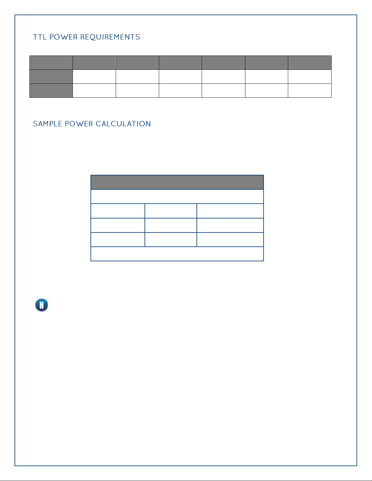
TTL POWER REQUIREMENTS......................................................................................................................... 35
SAMPLE POWER CALCULATION ..................................................................................................................... 35
SEAMAX APPLICATION SUITE ................................................................................................................... 36
SEAMAX OVERVIEW ................................................................................................................................... 36
COMMUNICATING VIA MODBUS .................................................................................................................... 36
SEAMAX SOFTWARE INSTALLATION .............................................................................................................. 37
DRIVER INSTALLATION FROM THE SEALEVEL DISK USING „AUTORUN‟ ................................................................. 37
DIRECT DRIVER INSTALLATION FROM THE SEALEVEL DISK .............................................................................. 39
INSTRUCTIONS FOR DOWNLOADED SOFTWARE INSTALLATION: .......................................................................... 39
UPGRADING TO THE CURRENT SEAIO DRIVER .................................................................................................. 39
MAXSSD CONFIGURATION & DIAGNOSTICS UTILITY ....................................................................................... 41
TROUBLESHOOTING SEAMAX ...................................................................................................................... 49
TROUBLESHOOTING ETHERNET & WIRELESS SEAI/O MODULES .......................................................................... 50
HARDWARE CONFIGURATION .................................................................................................................. 51
SETTING DEVICE ADDRESS (SLAVE ID) ........................................................................................................... 51
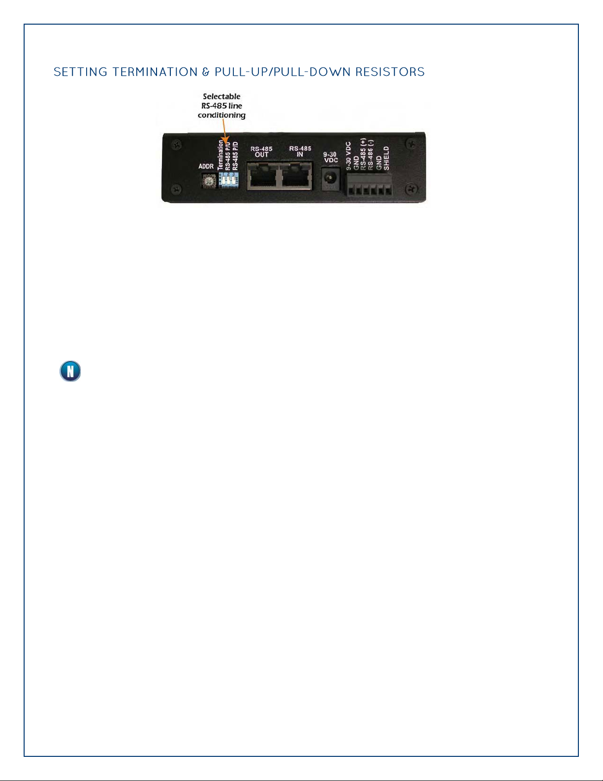
SETTING TERMINATION & PULL-UP/PULL-DOWN RESISTORS ............................................................................. 52
CONFIGURING THE “BASE” SEAI/O MODULE ................................................................................................... 53
CONFIGURING N-SERIES EXPANSION MODULES ............................................................................................... 54
CONFIGURING A WIRELESS (W-SERIES) MODULE .............................................................................................. 55
CONFIGURING A WIRELESS MODULE .............................................................................................................. 56
Page 3

©Sealevel Systems, Inc.
SL9049 - 11/2010
SeaI/O Manual
3
CONFIGURING A WIRELESS MODULE .............................................................................................................. 57
CONFIGURING AN ETHERNET (E-SERIES) MODULE ............................................................................................ 73
ADVANCED FEATURES ................................................................................................................................. 76
SEAI/O-463 RIBBON CABLE INSTALLATION ................................................................................................... 80
SEAI/O-470 JUMPER AND DIPSWITCH SETTINGS............................................................................................. 83
WIRING OPTIONS ...................................................................................................................................... 86
SEAI/O PASS-THROUGH CONNECTOR ........................................................................................................... 86
I/O WIRING – SEAI/O-462 AND 463 MODULES ............................................................................................ 88
I/O WIRING – SEAI/O-470 MODULES .......................................................................................................... 92
CONNECTOR PIN OUTS ............................................................................................................................... 97
MOUNTING OPTIONS ................................................................................................................................ 98
SEALATCH™ USB ....................................................................................................................................... 99
SEALATCH LOCKING USB CABLES ............................................................................................................. 100
ACCESSORIES .......................................................................................................................................... 101
POWER SUPPLIES....................................................................................................................................... 101
MOUNTING OPTIONS ................................................................................................................................ 103
CABLING OPTIONS .................................................................................................................................... 104
APPENDIX A – HANDLING INSTRUCTIONS ............................................................................................. 107
ESD WARNINGS ........................................................................................... ERROR! BOOKMARK NOT DEFINED.
APPENDIX B – HOW TO GET ASSISTANCE .............................................................................................. 108
TECHNICAL SUPPORT ................................................................................................................................ 108
APPENDIX C – WIRELESS MODULE INFORMATION ................................................................................... 71
WIRELESS SPECIFICATIONS ........................................................................................................................... 71
RSS-GEN SECTIONS 7.1.4 AND 7.1.5 STATEMENT FOR DEVICES WITH DETACHABLE ANTENNAS ......................... 72
WARRANTY .............................................................................................................................................. 109
NON-WARRANTY REPAIR/RETEST ............................................................................................................... 109
HOW TO OBTAIN AN RMA (RETURN MERCHANDISE AUTHORIZATION) .............................................................. 109
TRADEMARKS .......................................................................................................................................... 109
Page 4
©Sealevel Systems, Inc.
SL9049 - 11/2010
SeaI/O Manual
4
All SeaI/O modules are shipped with the following items. If any of these items is missing or
damaged please contact Sealevel for a replacement.
SeaI/O Data Acquisition Module
Sealevel SeaMAX Software CD
Do not connect the I/O module to the host until the software is installed.
Warning - The highest level of importance used to stress a condition where damage could
result to the product or the user could suffer serious injury.
Important– The middle level of importance used to highlight information that might not
seem obvious or a situation that could cause the product to fail.
Note – The lowest level of importance used to provide background information, additional
tips, or other non-critical facts that will not affect the use of the product.
Page 5

©Sealevel Systems, Inc.
SL9049 - 11/2010
SeaI/O Manual
5
Sealevel SeaI/O™ modules offer powerful data acquisition solutions that are perfect for a wide
range of applications and environments with easy interfacing to computers, controllers, and PLCs.
SeaI/O modules are available in various digital, analog, and serial I/O configurations. Each SeaI/O
model is designed for maximum flexibility and easy field wiring.
Ordering options allow connection to the host device via Wireless 802.11b/g, Ethernet, USB, RS485, or RS-232. Up to 246 expansion modules can be daisy chained together via RS-485 using
convenient pass-through connectors.
For easy software integration, application programs or 3rd party software can use the Sealevel
SeaMAXTM library or industry standard Modbus TCP (Ethernet & Wireless) and Modbus RTU (RS-232,
RS-485, and USB) protocols.
SeaI/O modules are perfect for a wide variety of applications and environments including:
Process Control
Data Acquisition
Broadcast Automation
Security
Facility Management
Page 6

©Sealevel Systems, Inc.
SL9049 - 11/2010
SeaI/O Manual
6
Choice of Connectivity:
o Wireless (802.11b/g)
o Ethernet
o USB
o RS-485
o RS-232
Supports Industry Standard Modbus TCP & RTU Protocols
Models Offering Choice of:
o Optically Isolated Inputs
o Reed Relay Outputs
o Form C Relay Outputs
o Open-collector Outputs
o TTL Interfaces
o Analog A/D & D/A
Status Indicator LEDs for Communication, Fault, and Status
Field Removable Terminal Block Connectors (most models)
9-30VDC Power Input
Power Input via Terminal Block or DC Jack
Daisy Chain up to 247 Modules
Extended Temperature Range Available (-40°C to +85°C)
Rugged Metal Enclosure
Compact Size – 7.5"(L) x 5.1"(W) x 1.3"(H)
Din Rail or Table Mount
Page 7

©Sealevel Systems, Inc.
SL9049 - 11/2010
SeaI/O Manual
7
Wireless 802.11b & 802.11g
SeaI/O-410W – 16 Optically Isolated Inputs/16 Reed Relay Outputs
SeaI/O-420W – 16 Optically Isolated Inputs/8 Form C Outputs
SeaI/O-430W – 32 Optically Isolated Inputs
SeaI/O-440W – 32 Reed Relay Outputs
SeaI/O-450W – 16 Form C Relay Outputs
SeaI/O-462W – 96 Bit TTL I/O (DB-78)
SeaI/O-463W – 96 Bit TTL I/O (50-Pin IDC)
SeaI/O-470W – 8 Inputs/8 Outputs/2 D/A & 16 A/D
SeaI/O-520W – 8 Optically Isolated Inputs/8 High-Current Form C Outputs
SeaI/O-530W – 16 Optically Isolated Inputs/16 High-Current Open Collector Outputs
SeaI/O-540W – 32 High-Current Open-collector Outputs
Ethernet 10/100 BaseT
SeaI/O-410E – 16 Optically Isolated Inputs/16 Reed Relay Outputs
SeaI/O-420E – 16 Optically Isolated Inputs/8 Form C Outputs
SeaI/O-430E – 32 Optically Isolated Inputs
SeaI/O-440E – 32 Reed Relay Outputs
SeaI/O-450E – 16 Form C Relay Outputs
SeaI/O-462E – 96 Bit TTL I/O (DB-78)
SeaI/O-463E – 96 Bit TTL I/O (50-Pin IDC)
SeaI/O-470E – 8 Inputs/8 Outputs/2 D/A & 16 A/D
SeaI/O-520E – 8 Optically Isolated Inputs/8 High-Current Form C Outputs
SeaI/O-530E – 16 Optically Isolated Inputs/16 High-Current Open-collector Outputs
SeaI/O-540E – 32 High-Current Open-collector Outputs
USB
SeaI/O-410U – 16 Optically Isolated Inputs/16 Reed Relay Outputs
SeaI/O-420U – 16 Optically Isolated Inputs/8 Form C Outputs
SeaI/O-430U – 32 Optically Isolated Inputs
SeaI/O-440U – 32 Reed Relay Outputs
SeaI/O-450U – 16 Form C Relay Outputs
SeaI/O-462U – 96 Bit TTL I/O (DB-78)
SeaI/O-463U – 96 Bit TTL I/O (50-Pin IDC)
SeaI/O-470U – 8 Inputs/8 Outputs/2 D/A & 16 A/D
SeaI/O-520U – 8 Optically Isolated Inputs/8 High-Current Form C Outputs
SeaI/O-530U – 16 Optically Isolated Inputs/16 High-Current Open-collector Outputs
SeaI/O-540U – 32 High-Current Open-collector Outputs
RS-485
SeaI/O-410M – 16 Optically Isolated Inputs/16 Reed Relay Outputs
SeaI/O-420M – 16 Optically Isolated Inputs/8 Form C Outputs
SeaI/O-430M – 32 Optically Isolated Inputs
SeaI/O-440M – 32 Reed Relay Outputs
SeaI/O-450M – 16 Form C Relay Outputs
SeaI/O-462M – 96 Bit TTL I/O (DB-78)
SeaI/O-463M – 96 Bit TTL I/O (50-Pin IDC)
SeaI/O-470M – 8 Inputs/8 Outputs/2 D/A & 16 A/D
SeaI/O-520M – 8 Optically Isolated Inputs/8 High-Current Form C Outputs
SeaI/O-530M – 16 Optically Isolated Inputs/16 High-Current Open-collector Outputs
SeaI/O-540M – 32 High-Current Open-collector Outputs
Page 8
©Sealevel Systems, Inc.
SL9049 - 11/2010
SeaI/O Manual
8
RS-232
SeaI/O-410S – 16 Optically Isolated Inputs/16 Reed Relay Outputs
SeaI/O-420S – 16 Optically Isolated Inputs/8 Form C Outputs
SeaI/O-430S – 32 Optically Isolated Inputs
SeaI/O-440S – 32 Reed Relay Outputs
SeaI/O-450S – 16 Form C Relay Outputs
SeaI/O-462S – 96 Bit TTL I/O (DB-78)
SeaI/O-463S – 96 Bit TTL I/O (50-Pin IDC)
SeaI/O-470S – 8 Inputs/8 Outputs/2 D/A & 16 A/D
SeaI/O-520S – 8 Optically Isolated Inputs/8 High-Current Form C Outputs
SeaI/O-530S – 16 Optically Isolated Inputs/16 High-Current Open-collector Outputs
SeaI/O-540S – 32 High-Current Open-collector Outputs
Expansion Units (Connect to Base Unit via RS-485)
SeaI/O-410N – 16 Optically Isolated Inputs/16 Reed Relay Outputs
SeaI/O-420N – 16 Optically Isolated Inputs/8 Form C Outputs
SeaI/O-430N – 32 Optically Isolated Inputs
SeaI/O-440N – 32 Reed Relay Outputs
SeaI/O-450N – 16 Form C Relay Outputs
SeaI/O-462N – 96 Bit TTL I/O (DB-78)
SeaI/O-463N – 96 Bit TTL I/O (50-Pin IDC)
SeaI/O-470N – 8 Inputs/8 Outputs/2 D/A & 16 A/D
SeaI/O-520N – 8 Optically Isolated Inputs/8 High-Current Form C Outputs
SeaI/O-530N – 16 Optically Isolated Inputs/16 High-Current Open-collector Outputs
SeaI/O-540N – 32 High-Current Open-collector Outputs
Page 9
©Sealevel Systems, Inc.
SL9049 - 11/2010
SeaI/O Manual
9
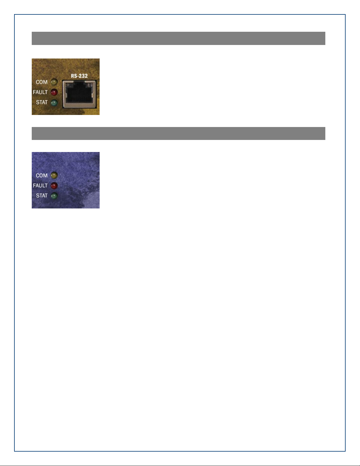
Depending on the interface type, your SeaI/O module may include additional accessories. Included
E Series (Ethernet)
Standard 7' CAT5 UTP Patch Cable (RJ45).
Standard 7' CAT5 UTP Crossover Cable (RJ45).
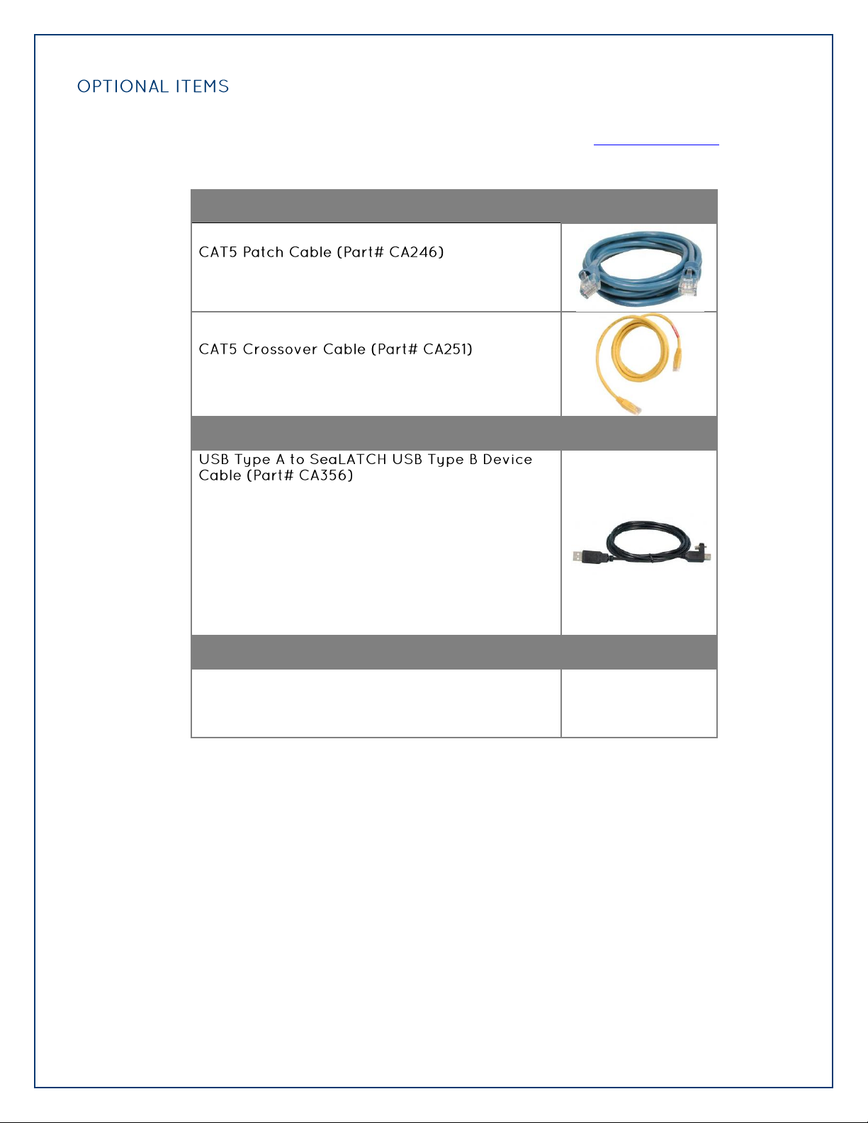
U Series (USB)
The CA356 is a USB device cable with a patent-pending
SeaLATCH USB type B connector and standard USB type A
connector. The metal thumbscrew on the type B
connector provides a secure metal-to-metal connection
to devices with SeaLATCH USB ports. This 72 inch cable
is included with all Sealevel USB products with an
integrated SeaLATCH USB type B port. SeaLATCH USB
cables are fully interchangeable with standard USB
cables!
M Series (RS-485)
No cable is included. Use twisted-pair wiring
connected to RS-485 signals via screw terminals on
left side of SeaI/O module.
accessories are listed below. All items can be purchased from our website (www.sealevel.com) by
calling our sales team at (864) 843-4343.
Page 10
©Sealevel Systems, Inc.
SL9049 - 11/2010
SeaI/O Manual
10
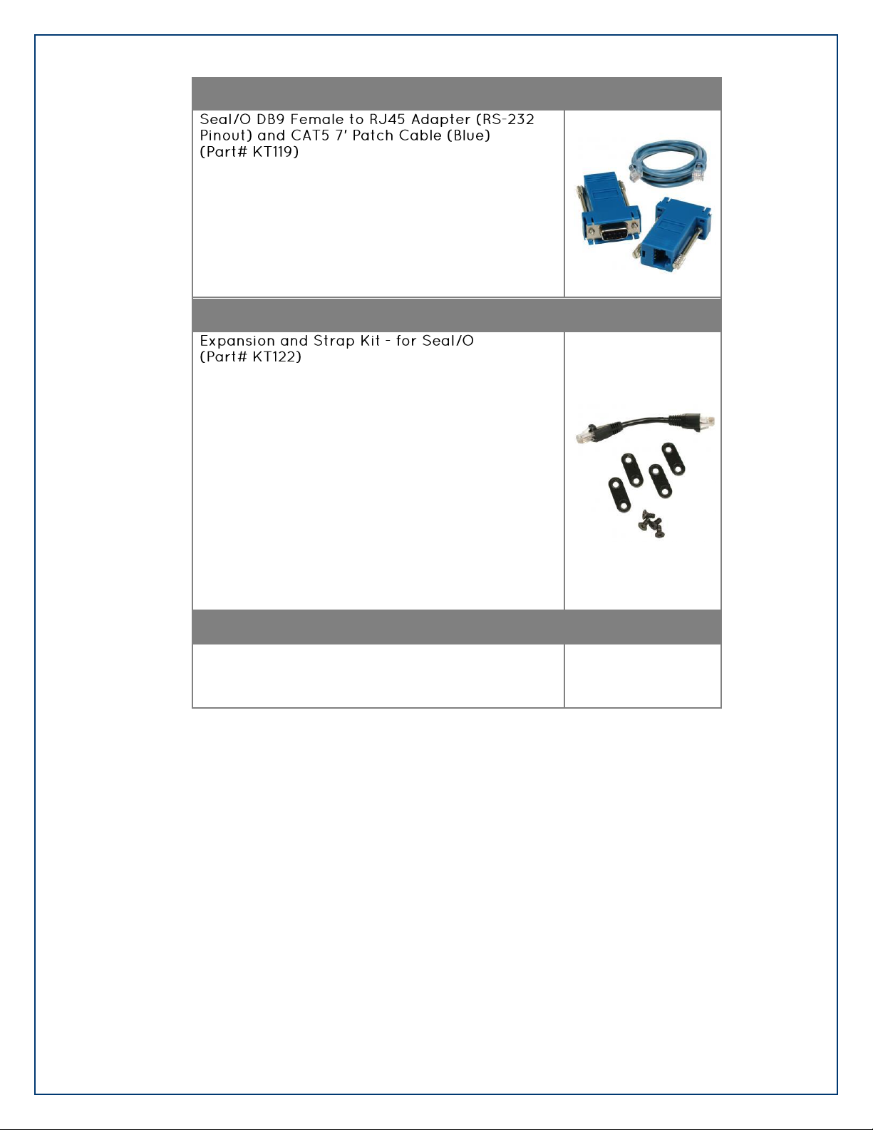
S Series (RS-232)
The KT119 includes a modular adapter with a DB9
female connector that plugs directly into any standard
DB9 RS-232 serial port and converts it to an RJ45
connection. Designed to easily connect SeaI/O RS-232
devices to any standard serial port via standard CAT5
patch cables. The KT119 ships with one DB9 female to
RJ45 adapter, Item # DB109, and a 7' CAT5 patch cable,
Item # CA246.
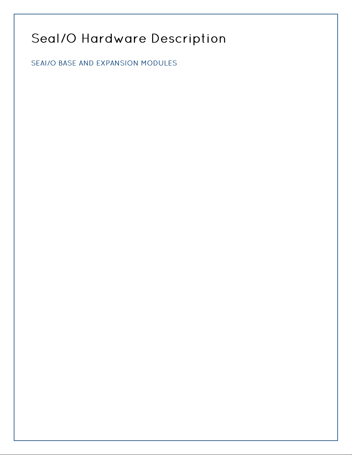
N Series (Expansion)
Included with all N-series expansion modules, the KT122
expansion and strap kit has four metal straps, four #440 screws, and a CA239 RS-485 interconnect cable. The
metal straps allow you to connect a Relio R1100 system
and multiple SeaI/O modules together in a stack. The
CA239 interconnect cable can be used to connect two
SeaI/O modules together via the RJ45 connectors. This
provides an easy method to cascade RS-485 signals, and
power and ground from one module to the next. When
used in combination with the KT123 flush mount bracket
kit, the KT122 expansion and strap kit can be used to
mount a stack of SeaI/O modules, including a Relio
R1100 system, in a variety of mounting positions and
locations.
All Models
Each SeaI/O unit is shipped with 4 adhesive rubber feet
that can be attached to the bottom of the enclosure to
enhance stability in table mount applications.
Page 11

©Sealevel Systems, Inc.
SL9049 - 11/2010
SeaI/O Manual
11
All SeaI/O modules have a default baud rate of 9600. If lower latencies are required, the baud rate
can be changed via the Sealevel utility, MaxSSD, included in your SeaMAX installation.
All modules, including expansion modules, must have the same baud rate or
communications errors will occur.
To change the baud rate, connect to a SeaI/O module using MaxSSD. If you need to change the
baud rate of multiple devices, check the “Broadcast to Multiple Modules” box. Select the desired
baud rate from the baud rate dropdown, and click “Set Settings.” If you are connected to the
modules via a COM port, you will need to reopen the COM port with the new baud rate.
SeaI/O 470
Baud rate: 9600
Reading 8 Digital Inputs Average Time: 32.00ms
Writing 8 Digital Outputs -- OFF state Average Time: 32.00ms
Writing 8 Digital Outputs -- ON state Average Time: 32.00ms
Reading 16 Analog-to-Digital Converters Average Time: 48.01ms
Writing to 2 Digital-to-Analog Outputs Average Time: 32.00ms
SeaI/O 470
Baud rate: 115200
Reading 8 Digital Inputs Average Time: 15.57ms
Writing 8 Digital Outputs -- OFF state Average Time: 15.92ms
Writing 8 Digital Outputs -- ON state Average Time: 16.21ms
Reading 16 Analog-to-Digital Converters Average Time: 16.25ms
Writing to 2 Digital-to-Analog Outputs Average Time: 16.26ms
Higher baud rates are more susceptible to electrical line noise. If you find that you are
receiving erroneous results, try lowering the baud rate or shortening your cables.
Page 12
©Sealevel Systems, Inc.
SL9049 - 11/2010
SeaI/O Manual
12
Base Modules connect to the host via one of the following interfaces:
W-Series – Wireless Modbus TCP
E-Series - Ethernet Modbus TCP
U-Series - USB Modbus RTU
M-Series - RS-485 Modbus RTU
S-Series - RS-232 Modbus RTU
After the base unit is installed, up to 246 additional SeaI/O N-Series Expansion Units can be added
to create an I/O network. These expansion modules interface via RS-485 and can be located local to
the Base SeaI/O device or remotely located up to 4000 feet away. Local installations should use the
5” CAT5 RS-485 pass-through cable (Part# CA239) shipped with each N-series module to connect.
Remote expansion modules should use RS-485 twisted pair wiring from the base unit connected via
the removable screw terminal connector.
For local installations power to the expansion modules is supplied from the Base unit via the passthrough connectors. For remote devices, separate power is required at each expansion unit. Refer
to the Power Options section of this manual for more information on SeaI/O power requirements
and power supply sizing.
Page 13
©Sealevel Systems, Inc.
SL9049 - 11/2010
SeaI/O Manual
13
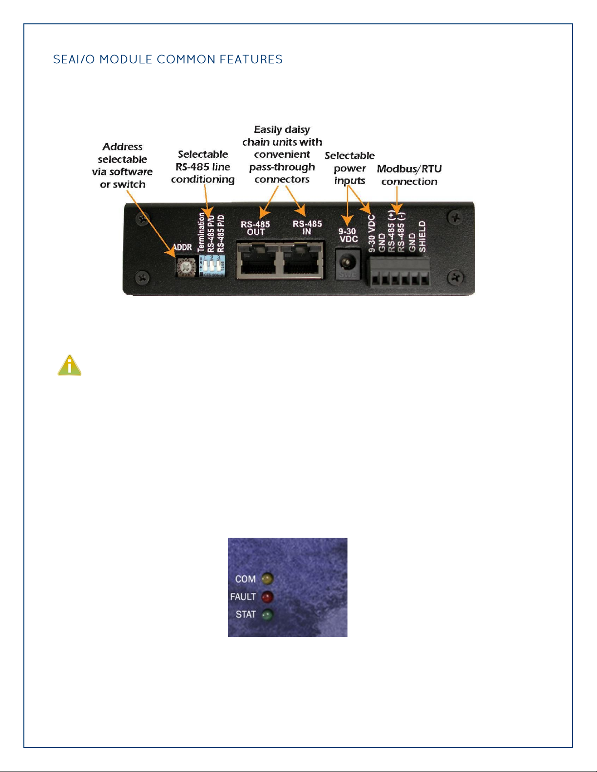
All SeaI/O modules include the same connectors and configuration options on the side of the unit:
RS-485 networks should have termination enabled on each end of the network. Pull-up and
pull-down resistors should also be enabled on the last device on the network. The 9-30VDC
input barrel connector is center positive.
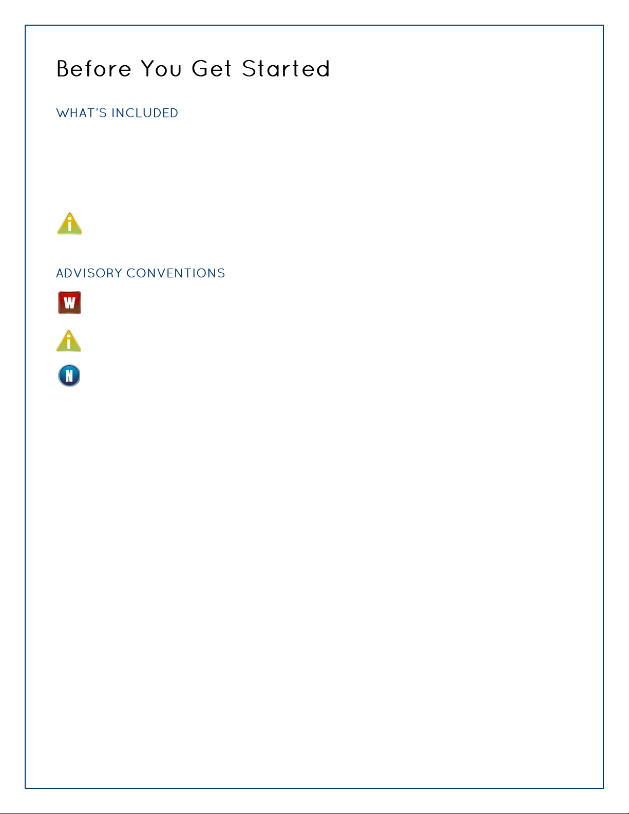
Status LEDs are also included on the front of all SeaI/O modules to indicate the following
information:
Communication (Yellow) – Blinks when data is transmitted
Fault (Red) – Lights when there is a problem with the device
Status (Green) – See Device Address Configuration section of this manual
o Blinks when the rotary “ADDR” switch is set to “0” and the default Slave ID is set to 247
o Lights steady when module is properly configured from the factory defaults
Page 14
©Sealevel Systems, Inc.
SL9049 - 11/2010
SeaI/O Manual
14
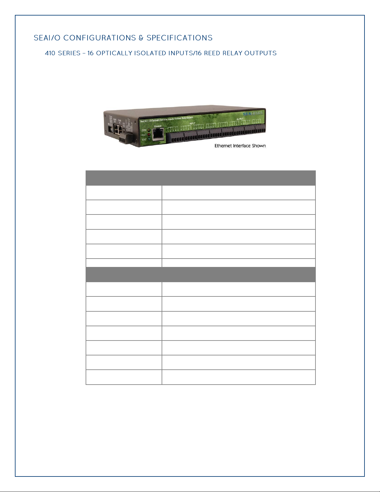
SeaI/O-410 modules provide 16 optically isolated inputs and 16 Reed relay outputs. Inputs can
Inputs
Type
16 non-polarized optically isolated inputs
Voltage Range
5-30VDC
Isolation
1250VAC RMS / 1800VDC
Input Resistance
6.2K Ohms in series
Response Time
4 microseconds
Outputs
Type
16 SPST Form A Reed relays
Power
10VA max.
Contact Voltage
60VDC max.
Contact Current
500mA max.
Operate Time
0.5ms max.
Bounce Time
0.5ms max.
Release Time
0.2ms max.
range from 5-30VDC, while the Reed relays provide long life switch closures that are well suited
for low current applications. Inputs and outputs are grouped into four-bit segments. Each
group shares a common for easy wiring via removable 3.5mm terminal blocks.
Page 15
©Sealevel Systems, Inc.
SL9049 - 11/2010
SeaI/O Manual
15
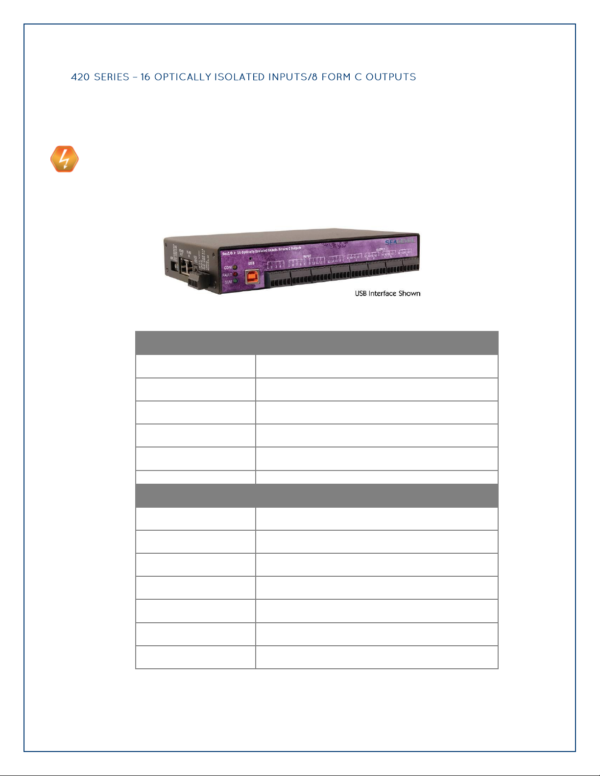
Inputs
Type
16 non-polarized optically isolated inputs
Voltage Range
5-30VDC
Isolation
1250VAC RMS / 1800VDC
Input Resistance
6.2K Ohms in series
Response Time
4 microseconds
Outputs
Type
8 SPDT Form C relays
Power
DC 30W/ AC 60 VA
Contact Voltage
60VDC max.
Contact Current
2A max.
Operate Time
2ms max.
Bounce Time
7ms max.
Release Time
1ms max.
The SeaI/O-420 provides 16 optically isolated inputs and 8 SPDT Form C relay outputs. Inputs
can range from 5-30VDC and provide 2500VAC RMS / 3500VDC isolation to ground. Each
output offers normally open and normally closed contact connections via 3.5mm field
removable terminal blocks.
USE EXTREME CAUTION!
High voltages will be present on the SeaI/O family of products when high voltage is
connected. Never handle the printed circuit board when high voltage signals are connected
to the board.
Page 16
©Sealevel Systems, Inc.
SL9049 - 11/2010
SeaI/O Manual
16
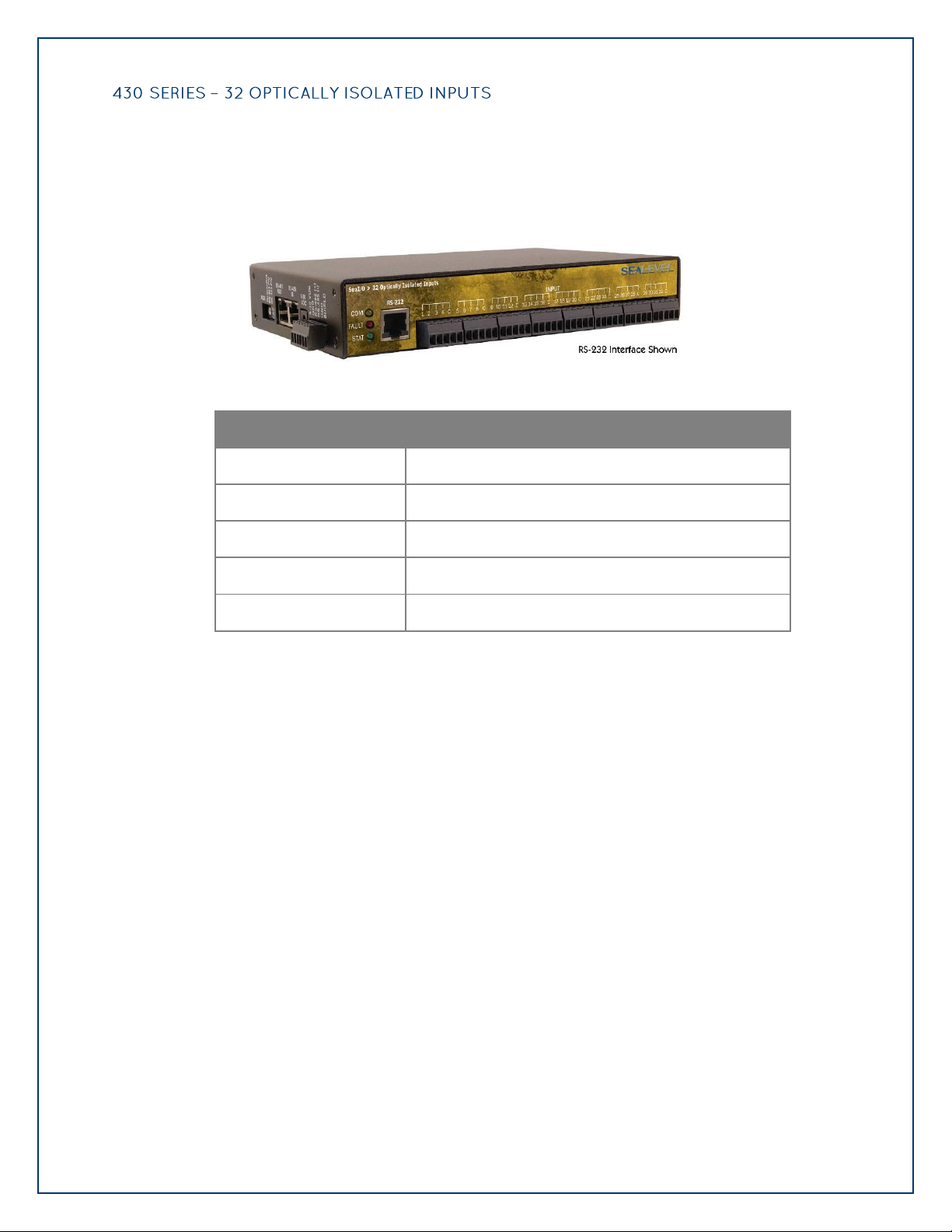
SeaI/O-430 modules provide 32 optically isolated inputs with 2500VAC RMS / 3500VDC
Inputs
Type
32 non-polarized optically isolated inputs
Voltage Range
5-30VDC
Isolation
1250VAC RMS / 1800VDC
Input Resistance
6.2K Ohms in series
Response Time
4 microseconds
external isolation and high channel-to-channel isolation. Ideal for low voltage monitoring
applications, connection to real world signals is made via convenient 3.5mm field removable
screw terminal connectors.
Page 17

©Sealevel Systems, Inc.
SL9049 - 11/2010
SeaI/O Manual
17
The SeaI/O-440 provides 32 SPST Form A dry-contact Reed relays. Reed relays offer long life
Outputs
Type
32 SPST Form A Reed relays
Power
10VA max.
Contact Voltage
60VDC max.
Contact Current
500mA max.
Operate Time
0.5ms max.
Bounce Time
0.5ms max.
Release Time
0.2ms max.
performance and fast response time. Convenient removable 3.5mm screw terminal blocks
compatible with 14-22 AWG wiring allow reliable connection to real world I/O.
USE EXTREME CAUTION!
High voltages will be present on the SeaI/O family of products when high voltage is
connected. Never handle the printed circuit board when high voltage signals are connected
to the board.
Page 18
©Sealevel Systems, Inc.
SL9049 - 11/2010
SeaI/O Manual
18
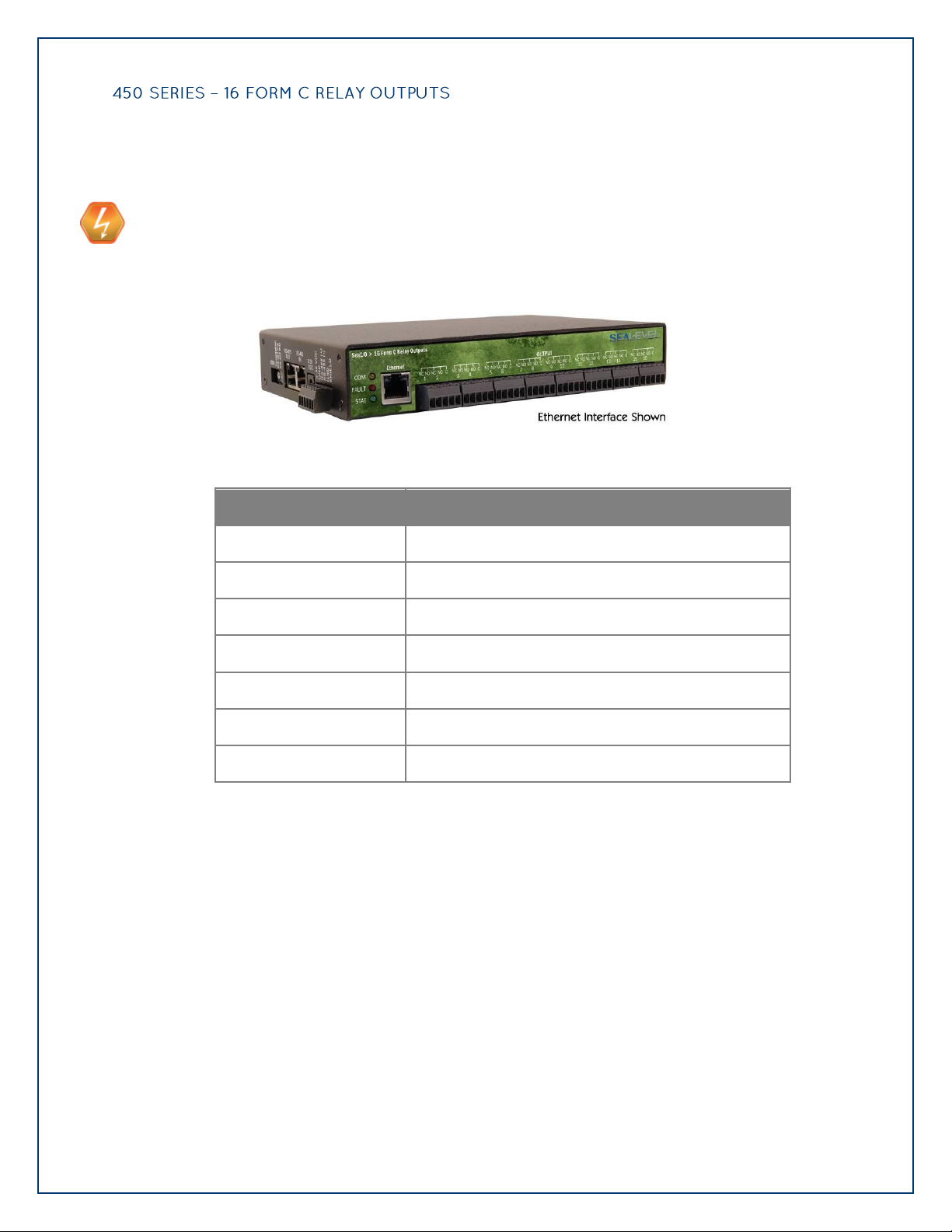
Control a variety of low voltage, low current devices with the SeaI/O-450. The module‟s 16
Outputs
Type
16 SPDT Form C relays
Power
DC 30W/ AC 60 VA
Contact Voltage
60VDC max.
Contact Current
2A max.
Operate Time
2ms max.
Bounce Time
7ms max.
Release Time
1ms max.
channels of highly reliable SPDT Form C relay outputs are rated for up to 60VDC @ 2A. Each
output offers normally-open and normally-closed contact connections via 3.5mm field
removable terminal blocks.
USE EXTREME CAUTION!
High voltages will be present on the SeaI/O family of products when high voltage is
connected. Never handle the printed circuit board when high voltage signals are connected
to the board.
Page 19
©Sealevel Systems, Inc.
SL9049 - 11/2010
SeaI/O Manual
19
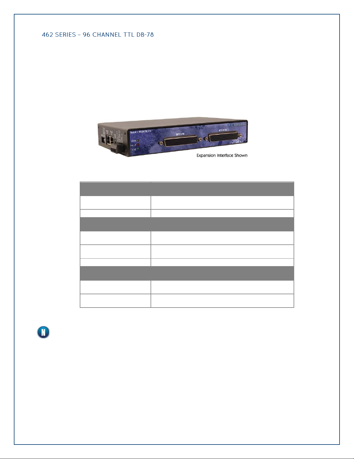
Perfect for driving industry-standard solid-state relay (SSR) racks, the SeaI/O-462 provides 96
Power Requirements
Max Output Power
+5VDC @ 1A (5W)
Inputs
Logic High
Max 0.8VDC
Logic Low
Min 2VDC
Outputs
Logic High
Max 0.5VDC @ 64mA
Logic Low
Min 2VDC @ 32mA
bits of buffered drive TTL I/O. Each DB-78 connector brings out 48 I/O bits addressable as six,
eight-bit ports. For easy connection to relay racks, Sealevel offers a six-foot cable (Part#
CA237) that terminates each DB-78 connector to two industry standard 50-pin IDC connectors.
Order part number 462x-KT and receive two CA237 cables with each unit.
The SeaI/O-462 uses 74ABT245 octal bi-directional transceivers to provide TTL input/output
capabilities and can sink 64mA and source 32mA. Each bit is pulled to +5V through a 10K ohm
pull-up resistor to insure each bit is at a known state when not driven.
The SeaI/O-462 modules are designed to work with industry standard solid-state relay racks
that expect negative logic to operate. The SeaI/O-462 modules expect negative logic on the
inputs.
Page 20
©Sealevel Systems, Inc.
SL9049 - 11/2010
SeaI/O Manual
20
Depending upon your application, you are likely to find one or more of the following items
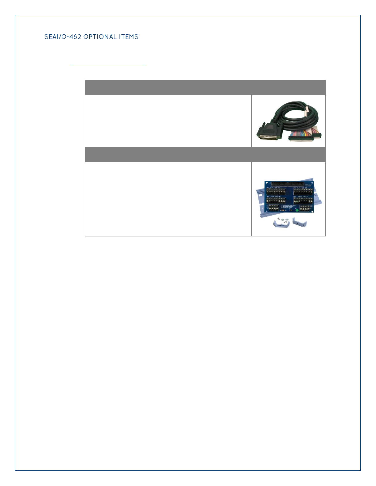
DB78 Male to (2) IDC 50-Pin Ribbon Connectors (Part# CA237)
The CA237 cable connects to SeaI/O TTL modules with a
DB78 female connector and splits out to dual industry
standard IDC 50-pin ribbon connectors. Perfect for
interfacing SeaI/O TTL modules to industry standard relay
racks where a jacketed cable is preferred over a ribbon
cable. Each leg of the CA237 is six feet in length.
Terminal Block Kit – 50 Pin Header to Screw Terminals (Part# TB07-KT)
The TB07-KT allows you to break out digital TTL signals,
+5 volts, and ground to screw terminals for easy field
connection of switches, discrete solid state relays, sensors,
etc. The TB07-KT ships with a terminal block, a 6” piece of
slotted Snap Track, and two DIN-rail mounting clips.
useful for interfacing the SeaI/O-462 to real-world signals. All items can be purchased from our
website (http://www.sealevel.com) or by calling 864-843-4343.
Page 21

©Sealevel Systems, Inc.
SL9049 - 11/2010
SeaI/O Manual
21
The SeaI/O-463 offers 96 bits of buffered drive TTL I/O via four internal industry-standard 50-
Power Requirements
Max Output Power
+5VDC @ 1A (5W)
Inputs
Logic High
Max 0.8VDC
Logic Low
Min 2VDC
Outputs *
Logic High
Max 0.5VDC @ 64mA
Logic Low
Min 2VDC @ 32mA
pin header connectors. The interface module addresses the 96 channels of I/O as 12 eight-bit
ports, each programmable as input or output. Using standard 50-pin IDC ribbon cables, connect
up to four industry standard relay racks for PC based control and automation of equipment
including sensors, switches, security control systems, and other industrial automation systems.
A metal strain relief bracket is included to secure the cables after installation.
The SeaI/O-463 uses 74ABT245 octal bi-directional transceivers to provide TTL input/output
capabilities and can sink 64mA and source 32mA. Each bit is pulled to +5V through a 10K ohm
pull-up resistor to insure each bit is at a known state when not driven.
The SeaI/O-463 modules are designed to work with industry standard solid-state relay racks
that expect negative logic to operate. The SeaI/O-463 modules expect negative logic on the
inputs.
Page 22
©Sealevel Systems, Inc.
SL9049 - 11/2010
SeaI/O Manual
22
Depending upon your application, you are likely to find one or more of the following items
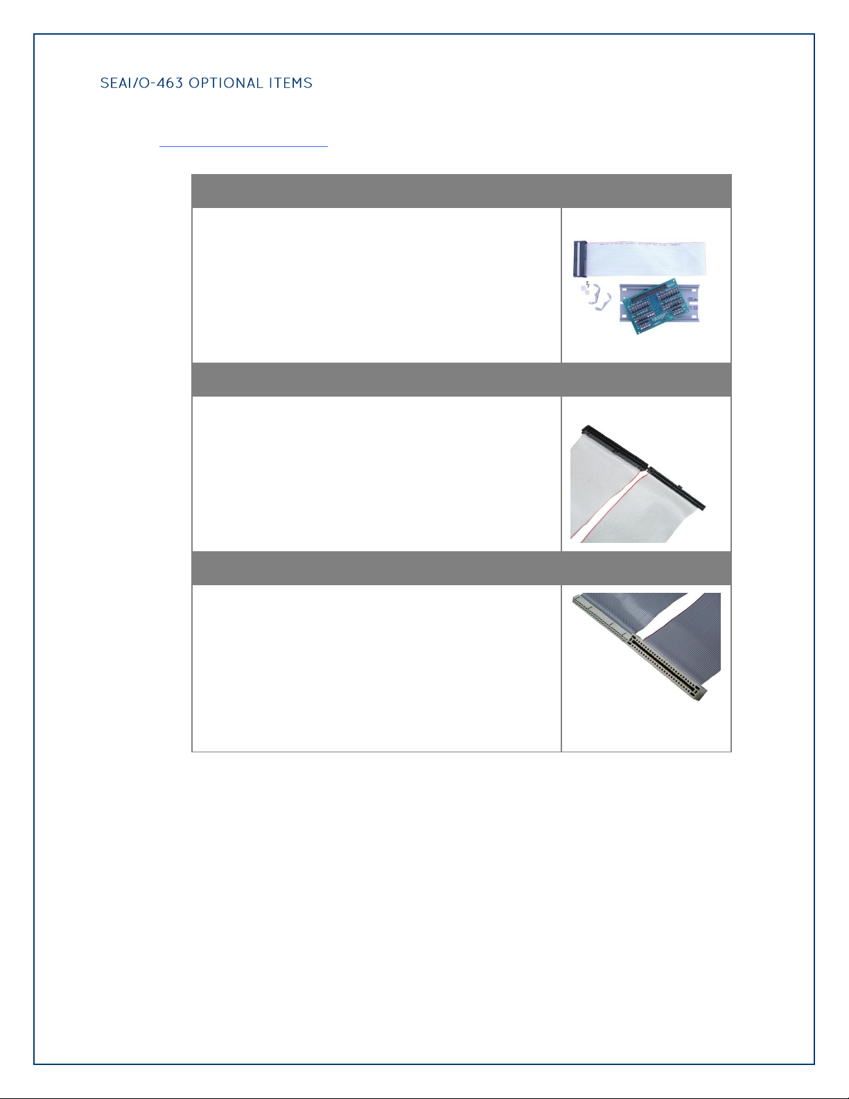
Terminal Block Kit - TB07 + CA167 Cable (Part# KT107)
The KT107 facilitates field wiring for applications
requiring connections other than to relay racks. The
KT107 kit includes the TB07 terminal block and CA167
ribbon cable. A 6” section of Snap track and DIN rail clips
are included for DIN rail mounting.
50-Pin IDC to 50-Pin IDC Ribbon Cable (Part# CA167)
50-Pin IDC to 50-Pin IDC Ribbon Cable, 40 in Length. Use
the CA167 to connect Sealevel TTL devices to solid-state
relay racks.
50-Pin IDC to 50-Pin Edge Connector Cable (Part# CA135)
50-Pin IDC to 50-Pin Edge Connector Ribbon Cable, 40 in
Length. Use the CA135 to connect Sealevel TTL devices to
solid-state relay racks with a 50-pin edge connector.
useful for interfacing the SeaI/O-463 to real-world signals. All items can be purchased from our
website (http://www.sealevel.com) or by calling +1 (864) 843-4343.
Page 23
©Sealevel Systems, Inc.
SL9049 - 11/2010
SeaI/O Manual
23
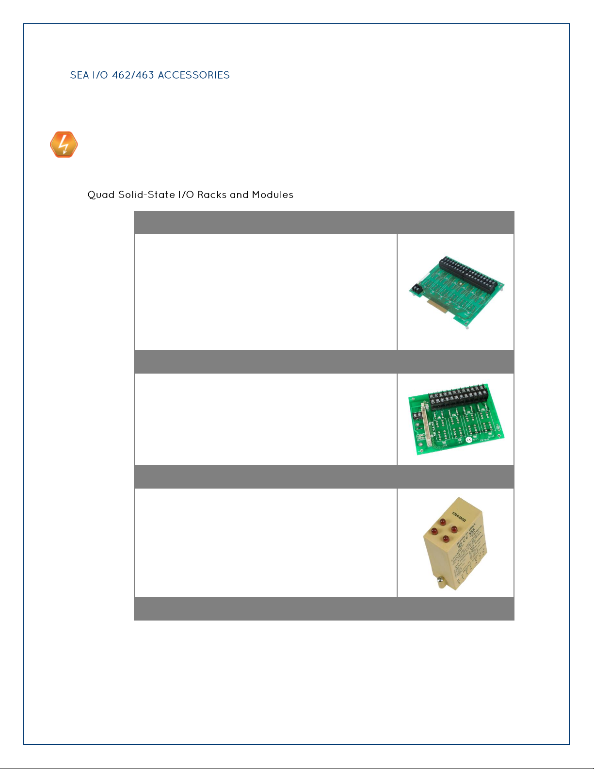
Quad 6-Position 24-Channel I/O Rack (Part# PB24HQ)
The PB24HQ I/O rack can be used with up to six quad I/O
modules, including input modules, output relays, override
relays, watchdog timers, and mechanical relays. On the
signal side, it features a 50-pin edge connector for easy
interface via standard IDC ribbon cables. Terminal blocks
accept insulated wire with stripped ends or ferrules. Each
power side point is individually isolated from each other.
Note:
SeaI/O 463 only. Use CA135 cable for interfacing.
Quad 4-Position 16-Channel I/O Rack (Part# PB16HQ)
The PB16HQ I/O rack can be used with up to four quad I/O
modules, including input modules, output relays, override
relays, watchdog timers, and mechanical relays. On the
signal side, it features a 50-pin header connector for easy
interface via standard IDC ribbon cables. Terminal blocks
accept insulated wire with stripped ends or ferrules. Each
power side point is individually isolated from each other.
Quad AC/DC Input Module (Part# IA5Q)
The IA5Q provides four discrete inputs that accept input
voltages from 90 to 140V AC/DC with a nominal input
voltage of 120V AC/DC. The module includes an LED for
each input for status indication.
Quad DC Input Module (Part# IB5Q)
The following accessories are suitable for use with both the SeaI/O 462 and SeaI/O 463
modules.
USE EXTREME CAUTION!
High voltages will be present on the SeaI/O family of products when high voltage is
connected. Never handle the printed circuit board when high voltage signals are connected
to the board.
Page 24

©Sealevel Systems, Inc.
SL9049 - 11/2010
SeaI/O Manual
24
The IB5Q provides four discrete inputs that accept input
voltages from 3.3VDC to 32VDC with a nominal input
voltage of 24VDC. The module includes an LED for each
input for status indication.
Quad AC Output Module (Part# OA5Q)
The OA5Q provides four discrete outputs capable of
switching voltages from 12 to 140V AC with a nominal
switching voltage of 120VAC. The maximum on-state
current is 3A and should be derated 40mA/deg. above
20C. Each output includes an LED for status indication.
Quad DC Output Module (Part# OB5Q)
The OB5Q provides four discrete outputs capable of
switching voltages from 3 to 60V DC with a nominal
switching voltage of 24VDC. The maximum on-state
current is 3A and should be derated 40mA/deg. above
20C. Each output includes an LED for status indication.
Page 25
©Sealevel Systems, Inc.
SL9049 - 11/2010
SeaI/O Manual
25
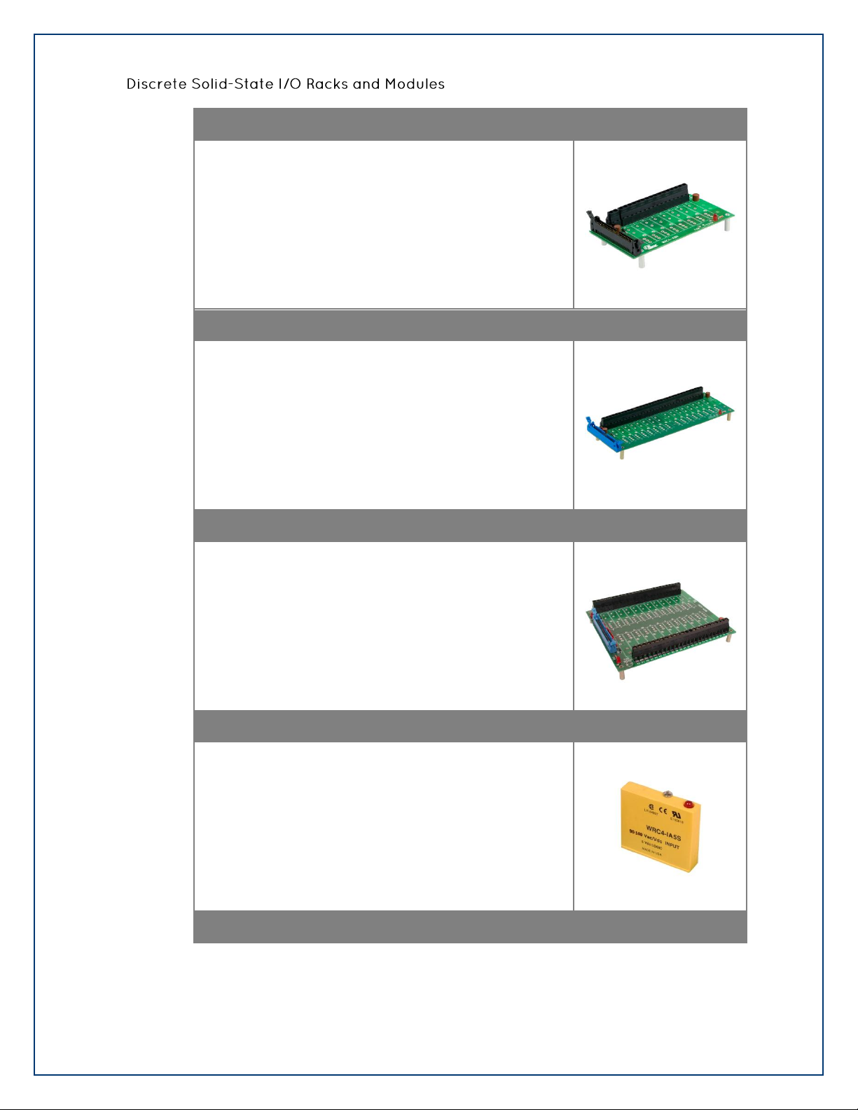
Discrete 8-Position I/O Rack (Part# PB8HS)
The PB8HS I/O rack can be used with up to eight discrete
I/O modules, including input modules, output relays,
override relays, watchdog timers, and mechanical relays.
On the signal side, it features a 50-pin header connector
for easy interface via standard IDC ribbon cables. Terminal
blocks accept insulated wire with stripped ends or ferrules.
Each power side point is individually isolated from each
other.
Discrete 16-Position I/O Rack (Part# PB16HS)
The PB16HS I/O rack can be used with up to sixteen
discrete I/O modules, including input modules, output
relays, override relays, watchdog timers, and mechanical
relays. On the signal side, it features a 50-pin header
connector for easy interface via standard IDC ribbon
cables. Terminal blocks accept insulated wire with stripped
ends or ferrules. Each power side point is individually
isolated from each other.
Discrete 24-Position I/O Rack (Part# PB24HS)
The PB24HS I/O rack can be used with up to twenty-four
discrete I/O modules, including input modules, output
relays, override relays, watchdog timers, and mechanical
relays. On the signal side, it features a 50-pin header
connector for easy interface via standard IDC ribbon
cables. Terminal blocks accept insulated wire with stripped
ends or ferrules. Each power side point is individually
isolated from each other.
Single Point Discrete AC/DC Input Module (Part# IA5S)
The IA5S provides a discrete input that accepts input
voltages from 90 to 140V AC/DC with a nominal input
voltage of 120V AC/DC. The module includes an LED for
status indication.
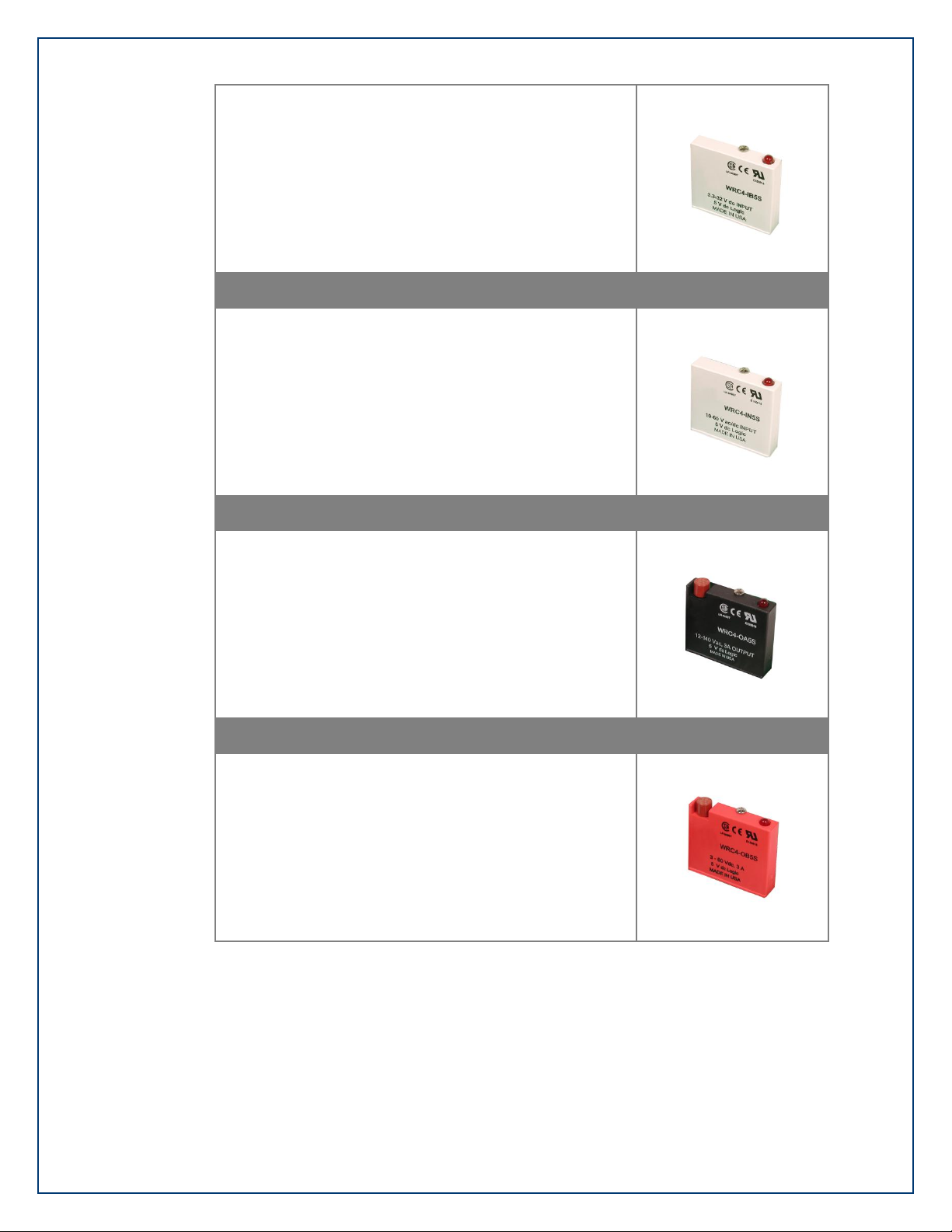
Single Point Discrete DC Input Module (Part# IB5S)
Page 26
©Sealevel Systems, Inc.
SL9049 - 11/2010
SeaI/O Manual
26
The IB5S provides a discrete input that accepts input
voltages from 3.3VDC to 32VDC with a nominal input
voltage of 24VDC. The module includes an LED for status
indication.
Single Point Discrete AC/DC Input Module (Part# IN5S)
The IN5S provides a discrete input that accepts input
voltages from 10 to 60V AC/DC with a nominal input
voltage of 24V AC/DC. The module includes an LED for
status indication.
Single Point Discrete AC Output Module (Part# OA5S)
The OA5S provides a discrete output capable of switching
voltages from 12 to 140V AC with a nominal switching
voltage of 120VAC. The maximum on-state current is 3A
and should be derated 33mA/deg. above 25C. The output
is fused at 4A and an LED is included for status indication.
Single Point Discrete DC Output Module (Part# OB5S)
The OB5S provides a discrete output capable of switching
voltages from 3 to 60V DC with a nominal switching
voltage of 24VDC. The maximum on-state current is 3A
and should be derated 33mA/deg. above 60C. The output
is fused at 4A and an LED is included for status indication.
Page 27
©Sealevel Systems, Inc.
SL9049 - 11/2010
SeaI/O Manual
27
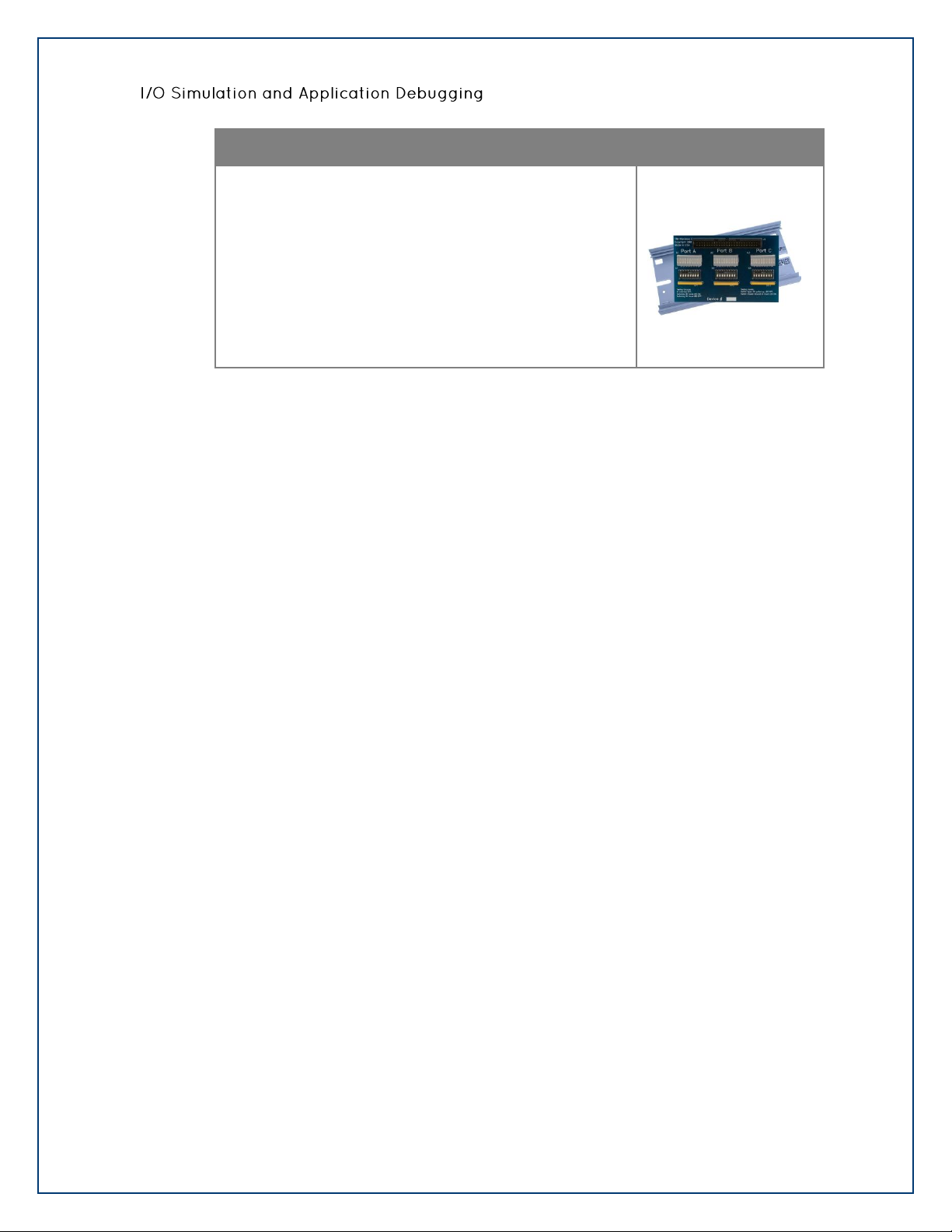
Terminal Block - 50-Pin Header – I/O Rack Simulation Module (Part# TA01)
The TA01 terminal block was developed to fully simulate
the operation and load characteristics of any industry
standard 24 channel relay rack. An LED block is included
for each 8 bit port. An LED corresponding to each port bit
illuminates when the simulated relay is energized. 8
position DIP switches are used to generate input status
changes. By using the TA01, control programs can be
debugged before going live on site to guarantee a
successful installation. The TA01 can be used with Sealevel
24, 48, and 96 Channel TTL Digital I/O products. Includes
TA01 Terminal Block and ST101 Snap Track.
Page 28
©Sealevel Systems, Inc.
SL9049 - 11/2010
SeaI/O Manual
28
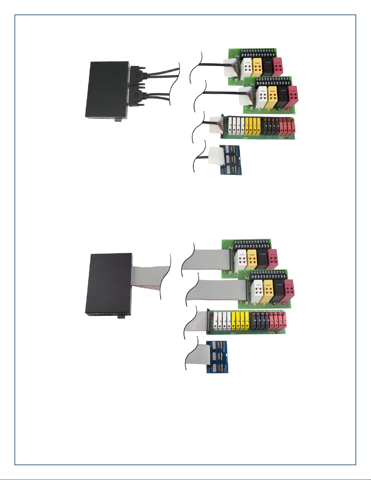
Figure 1. SeaI/O 462 connected to relay racks and a terminal adapter via (2) CA237 cables
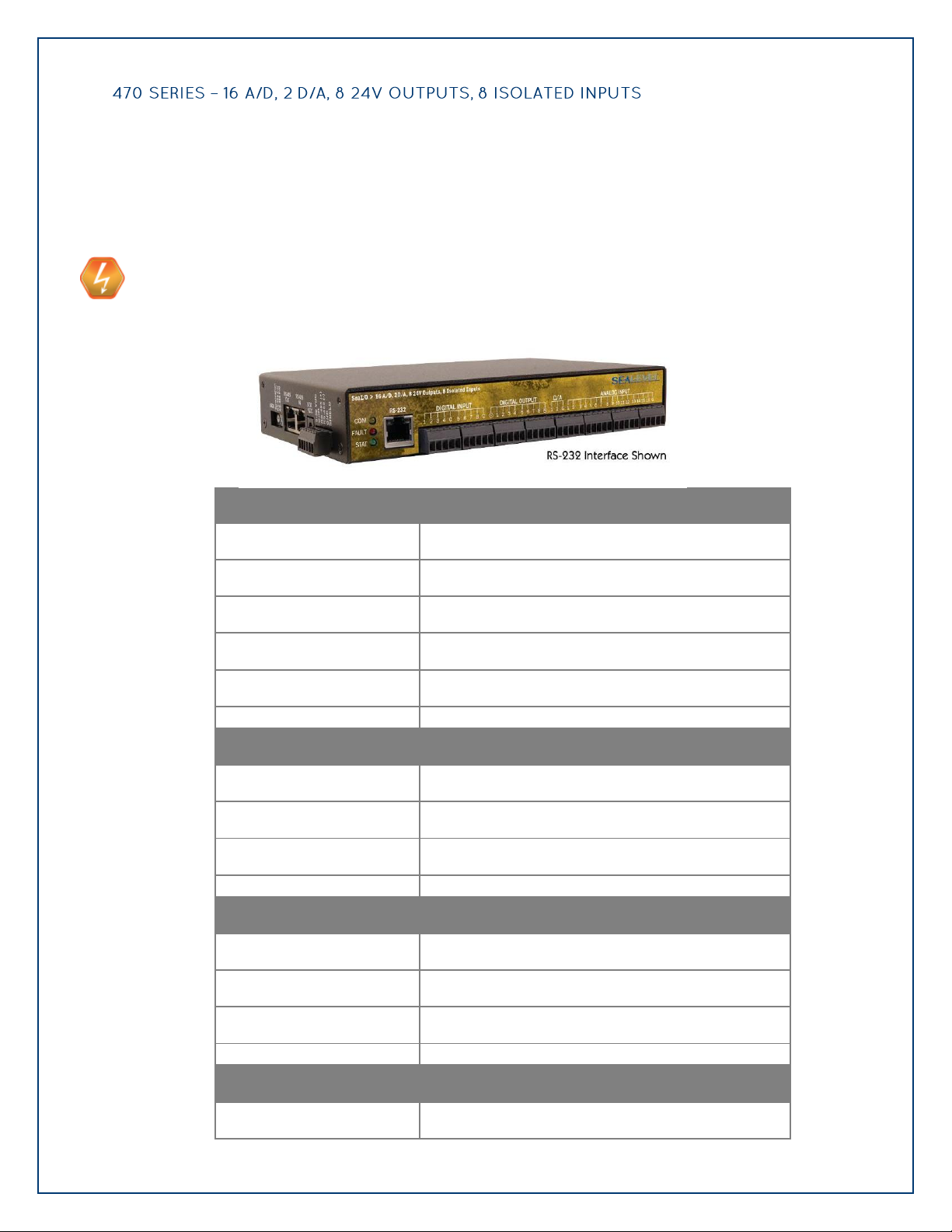
Figure 2. SeaI/O 463 connected to relay racks and a terminal adapter via (4) CA167 cables
Page 29
©Sealevel Systems, Inc.
SL9049 - 11/2010
SeaI/O Manual
29
Designed using the Maxim MAX197 successive approximation-type A/D chip, the SeaI/O-470
Optically Isolated Inputs
Type
8 non-polarized optically isolated inputs
Voltage Range
5-30VDC
Isolation
2500VAC RMS / 3500VDC
Input Resistance
6.2K Ohms in series
Response Time
4 microseconds
Open-collector Outputs
Output Voltage
Max. 30VDC
Output Current
Max. 500mA (single output)
Output Current
Max. 580mA (all outputs)
A/D Inputs
Number of Channels
8 differential or 16 single-ended
Resolution
12-bits
Sampling Rate
100K/s
A/D Input Range
Software Selectable
0-5V, 0-10V, +/-5V, +/-10V
provides eight differential or 16 single-ended 12-bit inputs. The A/D inputs can be individually
configured for sensing 4-20mA current loop signals. Additionally, the module provides two 12bit D/A output channels, eight optically isolated inputs, and eight open-collector outputs, ideal
for driving 24V devices commonly found in industrial environments. Perfect for a variety of data
acquisition/control and test & measurement applications, the SeaI/O-470 includes removable
screw terminals, which simplify field-wiring connections.
USE EXTREME CAUTION!
High voltages will be present on the SeaI/O family of products when high voltage is
connected. Never handle the printed circuit board when high voltage signals are connected
to the board.
Page 30
©Sealevel Systems, Inc.
SL9049 - 11/2010
SeaI/O Manual
30
Hardware Selectable
0-20mA current loop (for 4-20mA devices)
D/A Outputs
Number of Channels
2 single-ended
Resolution
12-bits
Output Range
0-5V, 0-10V
Load Resistance
Min. 2K
Page 31

©Sealevel Systems, Inc.
SL9049 - 11/2010
SeaI/O Manual
31
The SeaI/O-520 provides 8 optically isolated inputs and 8 SPDT high-current Form C relay
Inputs
Type
8 non-polarized optically isolated inputs
Voltage Range
5-30VDC
Isolation
2500VAC RMS / 3500VDC
Input Resistance
6.2K Ohms in series
Response Time
4 microseconds
Outputs
Type
8 SPDT High-Current Form C relays
Contact Voltage
250VAC/60VDC max.
Contact Current (AC)
6A max.
Contact Current (DC)
<30 VDC @5A max. / >30 VDC @500mA max.
Switching Capacity
5 VDC @ 100mA min.
Operate Time
10ms max.
Release Time
10ms max.
outputs. Inputs can range from 5-30VDC and provide 2500VAC RMS / 3500VDC isolation to
ground. Each output offers normally open and normally closed contact connections via 3.5mm
field removable terminal blocks.
Page 32
©Sealevel Systems, Inc.
SL9049 - 11/2010
SeaI/O Manual
32
Inputs
Type
16 non-polarized optically isolated inputs
Voltage Range
5-30VDC
Isolation
2500VAC RMS / 3500VDC
Input Resistance
6.2K Ohms in series
Response Time
4 microseconds
Outputs
Type
16 High-Current Open-collector Outputs
Isolation
2500VAC RMS / 3500VDC
Power
DC 60W max.
Contact Voltage
60VDC max.
Contact Current
Contact Current
1000mA max. (single output)
2000mA max. (all outputs per port)
Environmental
Operating Temperature
-25°C to +85°C (-13°F to 185°F)
Humidity
10% to 90% RH (non-condensing)
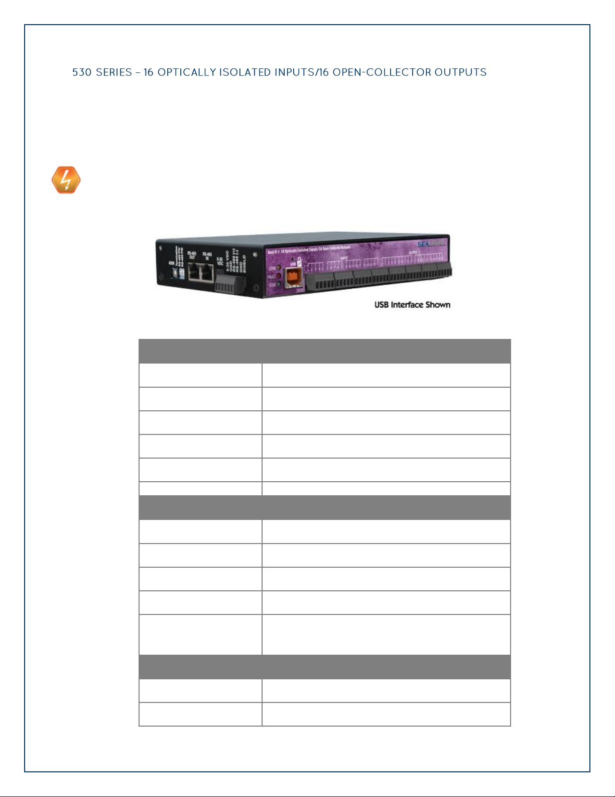
The SeaI/O-530 provides 16 optically isolated inputs and 16 open-collector outputs. Inputs
provide a range from 5-30VDC. Inputs are grouped into four-bit segments. Each group shares a
common for easy wiring via removable 3.5mm terminal blocks. Each open-collector output
circuit includes a flyback diode for protection when interfacing highly inductive loads, such as
DC motors. Outputs are grouped into two eight-bit ports which share high and low voltage
inputs.
USE EXTREME CAUTION!
High voltages will be present on the SeaI/O family of products when high voltage is
connected. Never handle the printed circuit board when high voltage signals are connected
to the board.
Page 33
©Sealevel Systems, Inc.
SL9049 - 11/2010
SeaI/O Manual
33
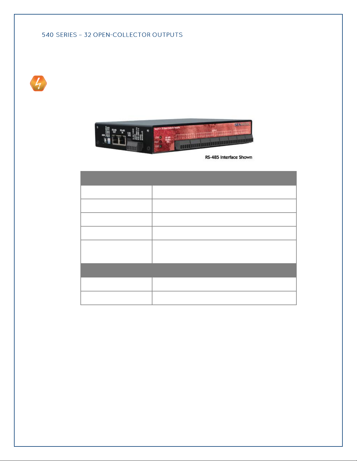
The SeaI/O-540 provides 32 open-collector outputs. Each open-collector output circuit includes
Outputs
Type
32 High-Current Open-collector Outputs
Isolation
2500VAC RMS / 3500VDC
Power
DC 60W max.
Contact Voltage
60VDC max.
Contact Current
Contact Current
1000mA max. (single output)
2000mA max. (all outputs per port)
Environmental
Operating Temperature
-25C to +85C (-13F to 185F)
Humidity
10% to 90% RH (non-condensing)
a flyback diode for protection when interfacing highly inductive loads, such as DC motors.
Outputs are grouped into four eight-bit ports which share high and low voltage contacts via
3.5mm terminal blocks.
USE EXTREME CAUTION!
High voltages will be present on the SeaI/O family of products when high voltage is
connected. Never handle the printed circuit board when high voltage signals are connected
to the board.
Page 34
©Sealevel Systems, Inc.
SL9049 - 11/2010
SeaI/O Manual
34
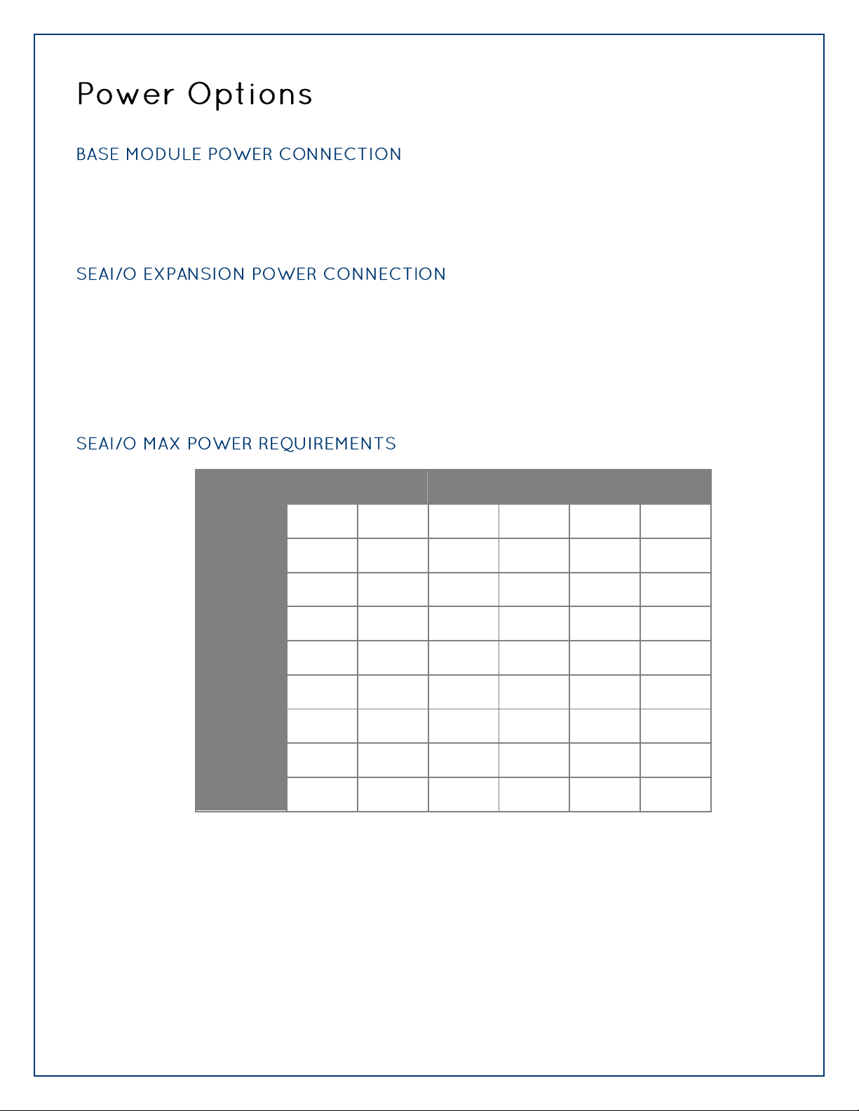
Base modules are powered from a 9-30VDC source using either the DC jack or screw terminals on
W-Series
E-Series
U-Series
M-Series
S-Series
N-Series
SeaI/O-410
3.4W
2.9W
1.7W
1.4W
1.6W
1.4W
SeaI/O-420
4.0W
3.5W
2.3W
2.0W
2.2W
2.0W
SeaI/O-430
2.4W
1.9W
0.7W
0.4W
0.6W
0.4W
SeaI/O-440
4.5W
4.0W
2.8W
2.5W
2.7W
2.5W
SeaI/O-450
5.8W
5.3W
4.1W
3.8W
4.0W
3.8W
SeaI/O-470
3.5W
3.0W
1.8W
1.5W
1.7W
1.5W
SeaI/O-520
5.5W
5.0W
3.8W
3.5W
3.7W
3.5W
SeaI/O-530
3.4W
2.9W
1.7W
1.4W
1.6W
1.4W
SeaI/O-540
3.9W
3.4W
2.2W
1.9W
2.1W
1.9W
the side of the unit. Sealevel offers several power supply choices to make connection easy (see the
Accessories chapter at the end of this document).
Each SeaI/O product, including the expansion modules, contains an onboard switching regulator
power supply rated for 9-30VDC. For local installations (less than 10‟ apart), expansion unit power
is usually supplied from the Base unit via the pass-through connectors. The number of expansion
modules that can be driven from the Base unit depends on the power source and number/type of
expansion units. Refer to the chart below for power requirements. For expansion modules mounted
remotely (greater than 10‟ apart), separate power is required at each expansion unit.
Page 35
©Sealevel Systems, Inc.
SL9049 - 11/2010
SeaI/O Manual
35
W-Series
E-Series
U-Series
M-Series
S-Series
N-Series
SeaI/O-462
2.5W
2.0W
0.8W
0.5W
0.7W
0.5W
SeaI/O-463
2.5W
2.0W
0.8W
0.5W
0.7W
0.5W
Example
Power (W)
Base Unit
SeaI/O-430U
0.7
Expansion 1
SeaI/O-410N
1.4
Expansion 2
SeaI/O-440N
2.5
4.6W Power Required
A typical application for SeaI/O products would use one Base module and several N-series units
in a local expansion configuration. In this arrangement, with power applied to the Base module
through either the DC jack or screw terminal connector and passed-through to the expansion
units, attention should be given to ensure the input power to the Base module is adequate.
In this application, Sealevel‟s Part# TR112 “wall wart” power supply is a good choice since it is
low-cost and supplies 24VDC @ 250mA (6W).
A complete listing of recommended power supplies is provided in the Accessories section of
this manual.
Page 36
©Sealevel Systems, Inc.
SL9049 - 11/2010
SeaI/O Manual
36
The SeaMAX Suite is a collection of configuration/diagnostic utilities and software libraries that
enable rapid application development. The SeaMAX API, included in the SeaMAX Suite, provides a
common API for Sealevel SeaI/O and SeaDAC data acquisition modules. SeaMAX is designed to
simplify application development by requiring little knowledge of the underlying communication
protocols of these devices and replacing low-level programming. SeaMAX is available in an
unmanaged library and a wrapper library that provides an interface to the API from managed code.
The following libraries and utilities are included in the SeaMAX Suite and are covered in this
chapter:
MaxSSD Configuration & Diagnostics utility
Ethernet Config utility
SeaMAX API
SeaMAX .NET API
The SeaMAX API documentation, installed with SeaMAX, explains the usage and API references,
including function calls and enumerations. Sealevel digital and analog I/O modules supported by
SeaMAX software are designed to work with third party applications via the SeaMAX API. To help
simplify application development, the complete API documentation and code samples are
automatically installed with the SeaMAX Suite and can be found in Windows by clicking Start All
Programs Sealevel SeaMAX Documentation. For convenience, Sealevel offers a PDF version of
the SeaMAX manual on our website. Example code is also included for several popular languages
and compilers.
Please contact Sealevel technical support with any questions regarding SeaMAX documentation:
Phone: (864) 843-4343
Email: support@sealevel.com
Sealevel SeaI/O modules are designed to integrate seamlessly into existing Modbus networks. The
supported command set will vary depending on the SeaI/O model number used. Specialized
diagnostic commands and other RTU specific codes are not supported. An overview of the Modbus
specification for both RTU and TCP connections is covered in detail in the interactive
documentation located on the Sealevel website at http://www.sealevel.com/software/SeaMAX/
The official Modbus specification can be found at http://www.modbus.org.
Page 37
©Sealevel Systems, Inc.
SL9049 - 11/2010
SeaI/O Manual
37
Proceed with installing the SeaMAX Software Suite using the software disk that was included with
your Sealevel I/O module. Software drivers are also available on the product webpage on the
Sealevel website at www.sealevel.com.
Do not connect the I/O module to the host until the software is installed.
To install Sealevel Systems software, you must log in as an administrator or have
administrator privileges in Windows.
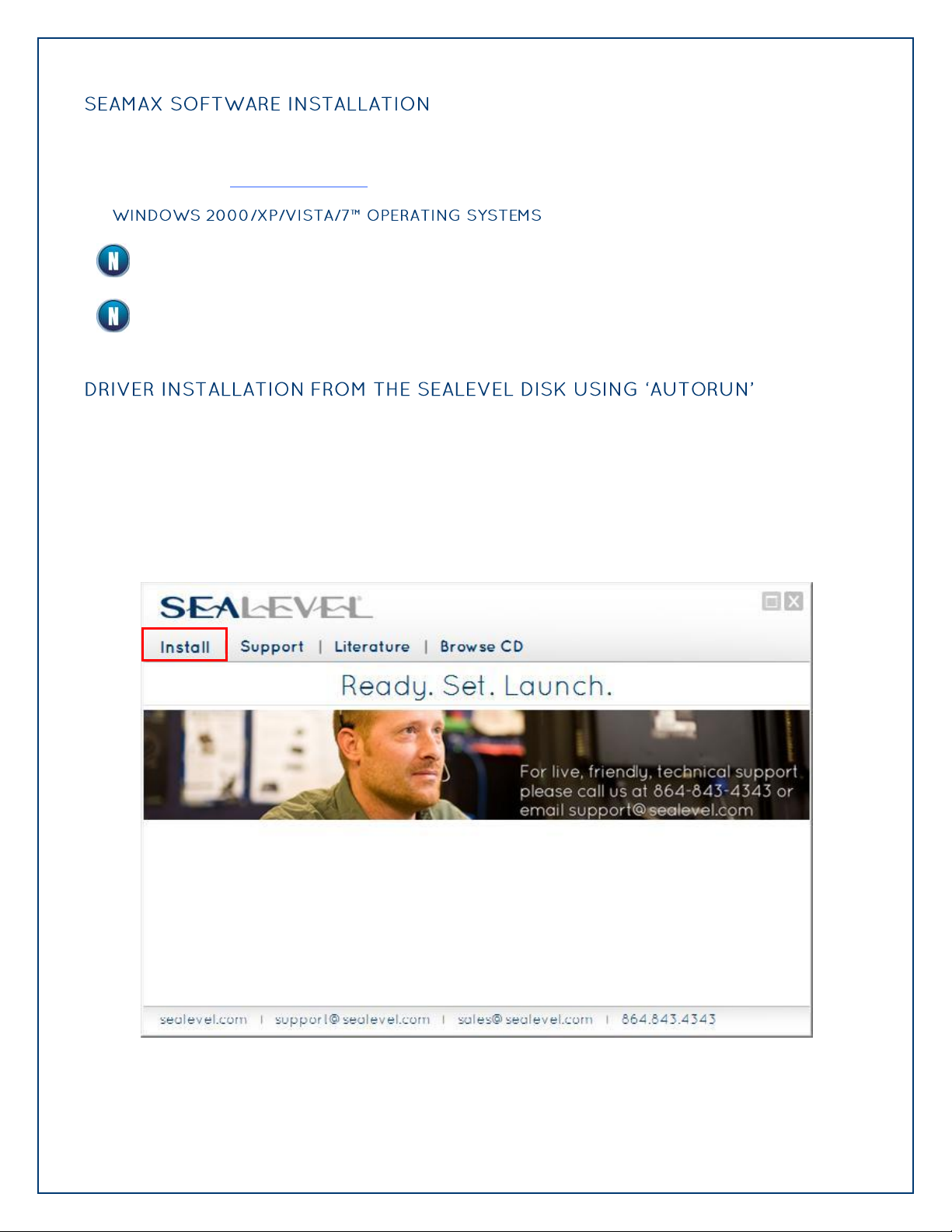
1. Insert the Sealevel Systems disk in to your optical drive.
2. If „AutoRun‟ is enabled for this drive the software will automatically launch.
3. Otherwise, navigate to the root directory of your optical drive and double-click the
„autorun.exe‟ application to launch the installation window.
4. Select „Install‟.
Page 38
©Sealevel Systems, Inc.
SL9049 - 11/2010
SeaI/O Manual
38
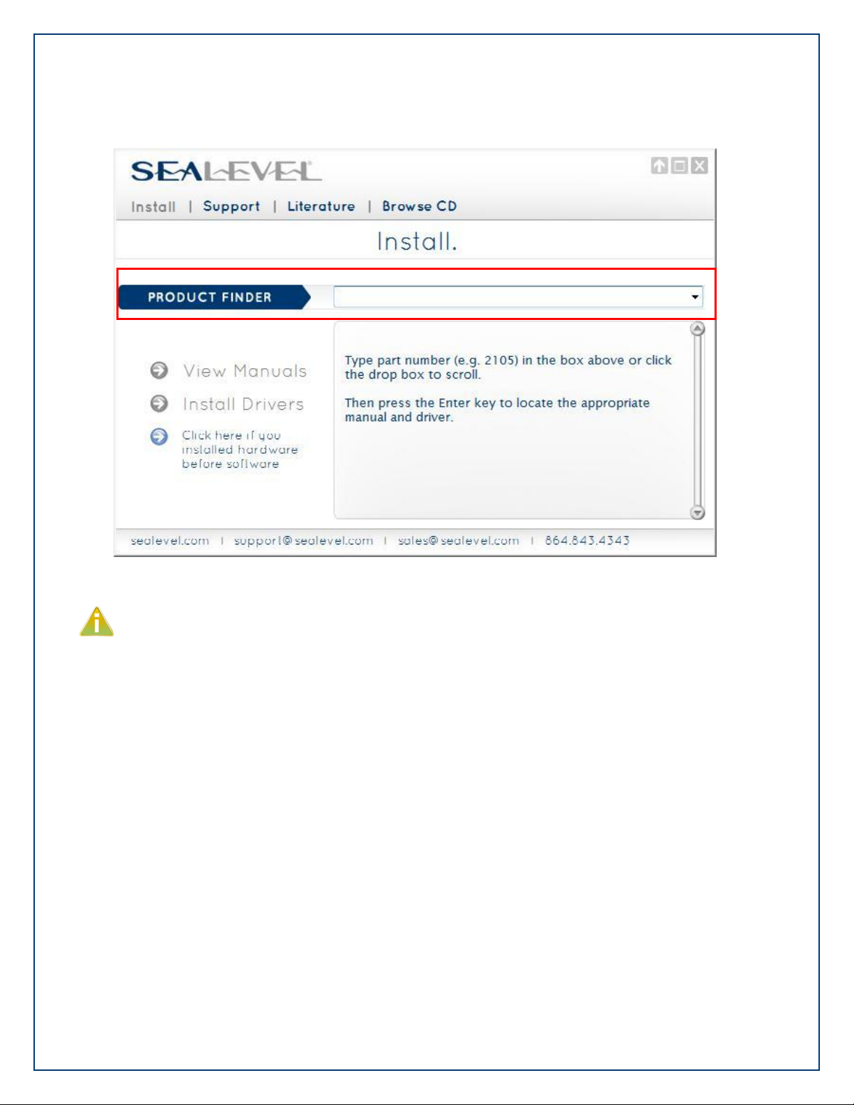
5. Type the part number for your adapter in the text box and click „Enter‟, or click on
the drop box to scroll from the listing to select your product.
If you installed your hardware prior to loading/installing the drivers, please click on the
„Click here if you installed hardware before software‟ button and follow the listed
instructions.
6. Click the „Install Drivers‟ button to launch the Installation Wizard.
7. When the InstallShield Wizard‟ window appears, click the „Next‟ button to initiate the
software installation.
8. When the „License Agreement‟ window appears, accept the terms and click „Next‟ to
continue. You can click the „Print‟ button to print out a copy of the agreement for
your records. If you do not accept the terms of the agreement, the installation will
stop.
9. When the „Ready to Install the Program‟ window appears, click the „Install‟ button to
install the software onto the hard drive of your computer. The files will be
automatically installed into the „C:\Program Files‟ folder on your computer.
10. The setup file will automatically detect the operating environment and install the
proper components. Next follow the information presented on the screens that
11. Refer to the Physical Installation section to connect and install your adapter.
follow. Once the installation is complete, close the disk installation window.
Page 39
©Sealevel Systems, Inc.
SL9049 - 11/2010
SeaI/O Manual
39
1. To install the driver executable from the Sealevel disk, browse the Sealevel Systems
disk for: Software\SeaIO\Windows\SeaIO Installer.exe
2. If you are using Windows Vista or newer operating systems, right click on the
installer executable and choose ‟Run as Administrator‟. If you are using an operating
system prior to Windows Vista, double click on the executable to launch the
Installshield and initiate the driver installation.
3. Please refer to step six above in the Disk Installation section and follow the
remaining installation steps.
1. To obtain the most current software driver package from Sealevel‟s website,
download from here:
SeaIO for Windows
SeaIO for Linux
2. Choose the link for the target operating system and click on the „Download File‟ link
to download the current driver.
3. Once downloaded, if you are using Windows Vista or newer operating systems, right
click on the installer executable and choose ‟Run as Administrator‟. If you are using
an operating system prior to Windows Vista, double click on the executable to
launch the Installshield and initiate the driver installation.
4. Please refer to step six above in the Disk Installation section and follow the
remaining installation steps.
1. Download the current SeaIO driver using the instructions from the Downloaded
Software Installation section above. Please take note of the destination directory it
will save to.
2. Uninstall the currently loaded driver SeaIO driver found in the Control Panel. Prior to
Windows Vista, SeaIO will be populated in the „Add/Remove Programs‟ list. In
Windows Vista and newer operating systems it will be found in the „Programs and
Features‟ list.
3. Navigate to the Device Manager and remove the Sealevel digital I/O adapter by right
clicking on the line item under „SeaI/O Device‟ and choosing „Uninstall’.
Page 40

©Sealevel Systems, Inc.
SL9049 - 11/2010
SeaI/O Manual
40
4. In the Device Manager under „Action‟, choose „Scan for hardware changes‟. This will
prompt the installation of the adapter and associate it with the newly installed SeaIO
driver.
If you are using a Wireless (W-series) or Ethernet (E-series) SeaI/O module, skip ahead to
either the Configuring a Wireless Module or Configuring an Ethernet Module sections of this
manual, before using MaxSSD.
Page 41
©Sealevel Systems, Inc.
SL9049 - 11/2010
SeaI/O Manual
41
The Sealevel Systems configuration utility, MaxSSD, is designed to simplify the installation,
configuration, and diagnostics of Sealevel I/O modules. MaxSSD is a Microsoft Windows application
and has been tested with Windows 2000, XP, Vista and Windows 7.
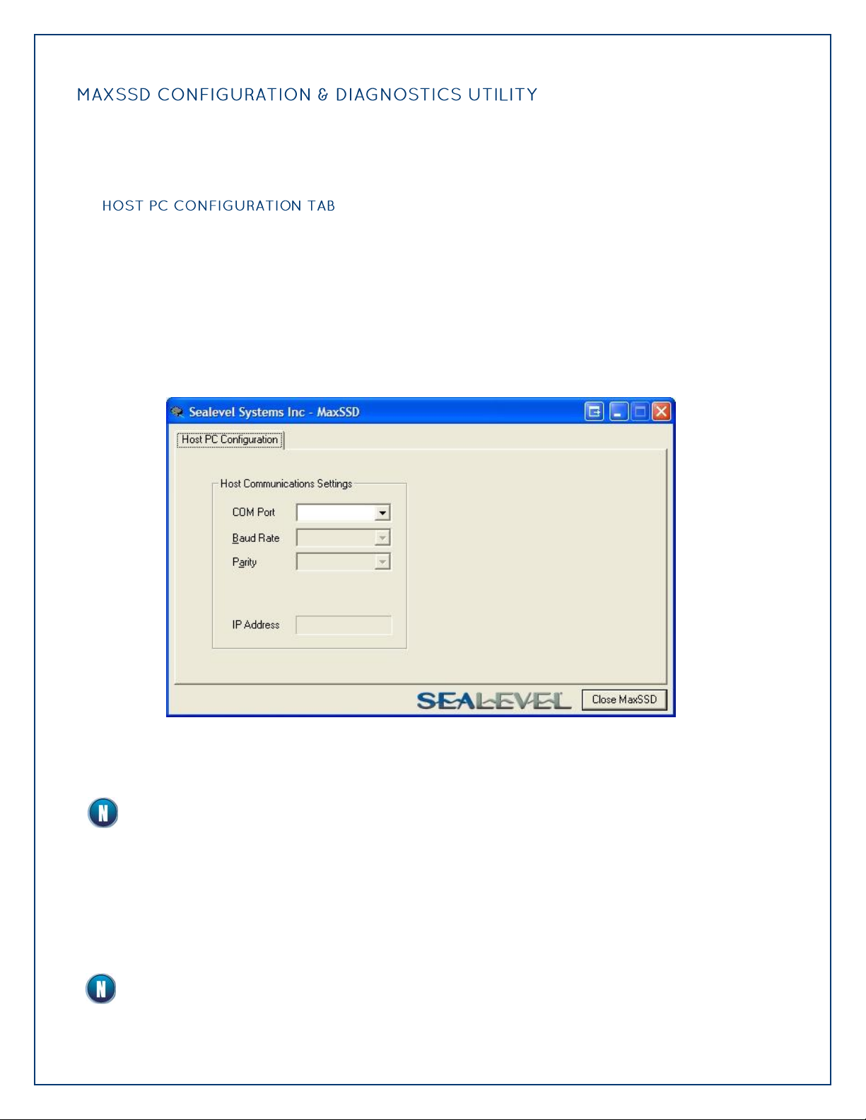
When you run the MaxSSD utility (Start All Programs Sealevel SeaMAX MaxSSD) it will
default to the “Host PC Configuration” tab. This tab allows the user to choose the initial
communication settings for the connected I/O device. The “COM Port” dropdown box allows the
selection of a serial COM port (from COM1 to COM256), and Ethernet (for Ethernet and Wireless
SeaI/O modules).
USB connected SeaI/O modules are installed as virtual COM ports. Using device manager,
expand “Ports (COM & LPT)” by clicking on the „+‟ next to the category, and locate the COM port
for your device and use it in the dropdown box in MaxSSD.
Once a COM port is selected, the baud rate and parity can be selected.
The baud rate and parity of the PC must match the settings of the Sealevel I/O module to be
configured. The factory default settings for all Sealevel I/O modules are 9600 baud and no
parity.
To communicate with a SeaI/O Ethernet or Wireless 802.11b/g module, select “ETHERNET” from
the “COM Port” dropdown box. When Ethernet is selected, MaxSSD searches for any SeaI/O
Ethernet or Wireless modules on the network and displays their IP addresses in the “Available
Ethernet Devices” list box (not shown). When an IP address is selected from the list box, a
socket is opened to the SeaI/O module and it is ready for communication.
If no IP address is shown when using Ethernet modules, review the previous Hardware
Configuration section, or proceed to the Troubleshooting section at the end of this manual.
Page 42

©Sealevel Systems, Inc.
SL9049 - 11/2010
SeaI/O Manual
42
Once the host computer is configured correctly, the “SeaI/O Configuration” tab becomes
available. Before communicating with a SeaI/O module, the configuration utility must
determine if there is an I/O module at that slave ID address, and if so, what type of module it is.
This is the purpose of the Get operation.
To perform a Get operation, first select the slave ID to which the module is configured. SeaI/O
modules are shipped at hardware setting 0 (labeled “ADDR” on the left side of the module) and
slave ID 247 by default. All other slave ID addresses (from 1 to 246) are available. However,
each daisy chained SeaI/O module must have a unique slave ID address - no duplicates are
allowed.
Once a slave ID is selected, click the “Get SeaIO Module Settings” button. After a short delay,
the information for that I/O module should be displayed. If no information appears, verify the
slave ID, host settings, and baud rates are correct and make changes, if necessary. Check the
hardware settings (on the left side of the module) and try again.
Page 43
©Sealevel Systems, Inc.
SL9049 - 11/2010
SeaI/O Manual
43
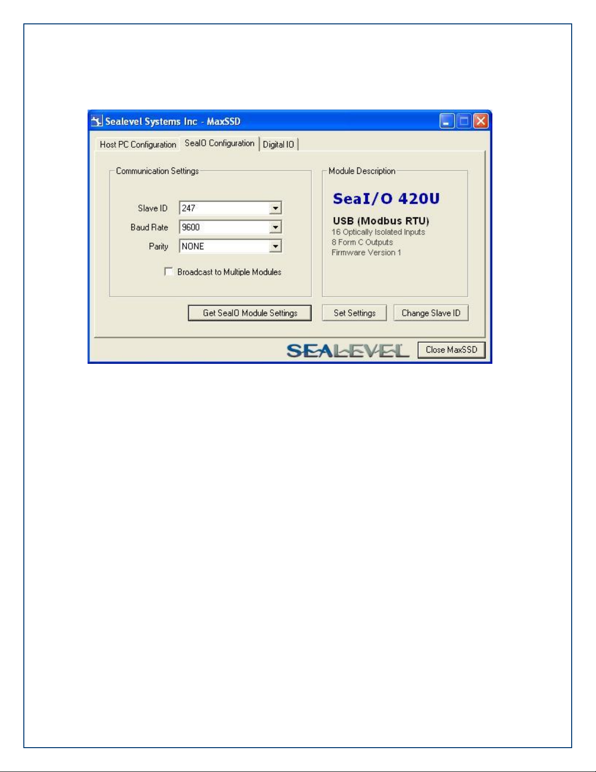
After the Get command is executed, the “Module Description” frame will display the model type,
description, firmware version number, interface, and I/O type. In the example shown, the
module found at slave ID 247 is a SeaI/O-420 module with a USB (Modbus RTU) interface. The
“Set Settings” and “Change Slave ID” buttons will also be enabled for this module.
After a successful Get operation, additional tabs may be displayed in MaxSSD, depending on the
found device model. These tabs display device I/O and allow easy configuration for all SeaMAX
supported devices.
The “Broadcast to Multiple Modules” checkbox, along with the “Set Settings” button can be used
to change the baud rate and parity on multiple SeaI/O modules at once. This function only
works with SeaI/O modules connected together via the pass-through connectors.
MaxSSD broadcasts a set data rate and set parity command to all devices on the RS-485 bus,
but only those modules listening at the current baud rate will be able to receive and respond.
For example, if you have five SeaI/O modules chained together and two are set to 9600 bps and
no parity and three are set to 115.2k bps and the PC is set to 9600 bps, only the two modules
set to 9600 bps will receive the broadcast set data rate and parity message.
Page 44

©Sealevel Systems, Inc.
SL9049 - 11/2010
SeaI/O Manual
44
The broadcast feature sets the Ethernet SeaI/O (E-series) module‟s TCP/IP to RS-485
translation data rate independently of the SeaI/O module itself. If you set the data rate to
115.2K bps via a MaxSSD broadcast command, both the RS-485 port and the Ethernet port
will respond thereafter to 115.2K bps, as expected. However, if you reset the SeaI/O
module, by rotating the rotary switch clockwise one complete revolution, the RS-485 port
will reset to 9600 bps and no parity, but the Ethernet port will remain unaffected. To
restore communications, broadcast another set data rate and parity command (9600 and no
parity) via MaxSSD.
Page 45

©Sealevel Systems, Inc.
SL9049 - 11/2010
SeaI/O Manual
45
The “Digital IO” tab of MaxSSD is displayed when using Sealevel I/O devices featuring discrete
inputs and outputs. It displays the device‟s current input and/or output status in an intuitive
and usable manner.
When displaying SeaI/O, the “Digital IO” tab displays inputs and outputs in groupings (or banks)
of eight. Therefore, a Sealevel I/O device with 16 inputs and 8 outputs would show two banks
of inputs and one bank of outputs.
When banks of inputs are displayed, the status LEDs update on each of the banks automatically.
This allows you to actively monitor external signals.
With a bank of outputs, the output coils can be set using the buttons below each output LED. As
each coil is set, the I/O module is read. The corresponding status LED in the “Digital IO” tab
indicates the state of the coil. In the example below, a SeaI/O module with 16 Reed relays is
shown.
Page 46

©Sealevel Systems, Inc.
SL9049 - 11/2010
SeaI/O Manual
46
The “A/D Inputs” tab displays the current state of the analog-to-digital channels for Sealevel I/O
devices that feature A/D inputs. Settings are provided for both device wide and per-channel
configuration.
The “Device Configuration” selection drop-box adjusts the arrangement and function of the A/D
input channels. Input channels are displayed as banks (groups of eight). Each channel is range
configurable via the voltage range dropdown list. Both the channel voltage range and devicewide configuration are set on a dropdown list. There is no need to save your settings – they are
automatically saved to the device as you select the various configuration options.
“10x Hardware Gain Enabled” checkbox – Indicates whether or not the onboard hardware gain
jumper is currently set. This option is not user configurable – it only reflects the status of the
onboard hardware jumper settings. Set the hardware jumper to enable this functionality, which
allows smaller voltages to be measured more accurately (e.g., a 0-1V input signal can be
measured more accurately by enabling the 10x hardware gain jumper and setting the SeaI/O470 A/D input channel for 0-10V range).
“Show Hexadecimal Values” checkbox – Displays the values returned by the A/D converter as a
hexadecimal value without converting the values to engineering units (i.e., Amps or Volts)
Page 47

©Sealevel Systems, Inc.
SL9049 - 11/2010
SeaI/O Manual
47
The “D/A Outputs” tab is useful for manually setting the digital to analog output voltages on
applicable Sealevel I/O devices with D/A channels. A preliminary diagnostics utility (see
following page) has been provided to verify proper hardware functionality.
The D/A outputs of the SeaI/O-470 are factory set for 0-10V. To configure the D/A outputs for
0-5V, you will need to open the enclosure and set the correct jumpers. Refer to the Hardware
Configuration section of this manual for instructions on opening the enclosure and accessing
the correct jumpers.
To adjust a particular channel‟s output voltage, drag the slider until the desired voltage is
displayed in the window on the right side. Also, you may type the desired voltage directly into
the voltage display and then confirm your entry by pressing the „Enter‟ key on your keyboard.
The output voltage will not change until the „Enter‟ key is pressed or you have clicked on
the window anywhere outside of the text entry field.
Page 48
©Sealevel Systems, Inc.
SL9049 - 11/2010
SeaI/O Manual
48
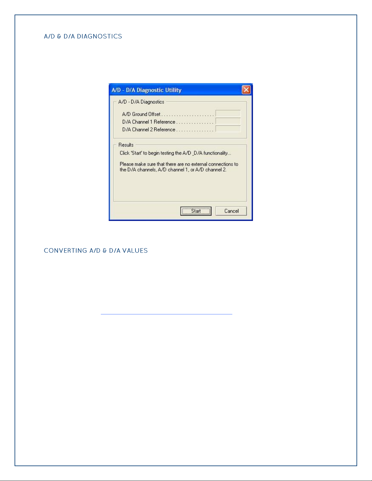
To check basic functionality of both the A/D and D/A converters, press the “Diagnostics Utility”
button on the “D/A Outputs” tab (shown on the previous page) and then press the “Start”
button, as shown below. Any errors will be shown in the “Results” pane. If any errors occur,
please contact technical support for further help.
To properly use the values returned from the SeaI/O-470 module‟s A/D channels, the
application program must convert the returned values to engineering units (voltage). Likewise,
the application program must output the correct value to the I/O module‟s D/A outputs to
generate the desired voltage.
The conversion formulas will vary depending on how the I/O module is configured. The
formulas and their uses are covered in detail in the interactive documentation located on the
Sealevel website at http://www.sealevel.com/software/SeaMAX/. For ease of use, SeaMAX
functions to convert A/D and D/A values have been provided. Use of these functions is also
detailed in the SeaMAX Software Manual.
Page 49

©Sealevel Systems, Inc.
SL9049 - 11/2010
SeaI/O Manual
49
Following these simple steps can eliminate most common problems.
1. Read this manual thoroughly before attempting to install the device in your system.
2. Uninstall any previous versions of the SeaMAX software before installing any new
versions.
3. Install SeaMAX software before connecting any Sealevel I/O devices. Installing
the software places the necessary files in the proper locations on your system. After
installing the software, proceed with adding the hardware.
4. When installing SeaI/O modules, connect them one at a time. The “base” module
must be properly configured and communicating successfully with the host before
you can add additional expansion modules. Verify that each expansion module can
communicate before connecting additional expansion modules.
5. Confirm that all screw terminal connections are correct and secure and that the
correct cables are being used, including network cables (crossover vs. patch cables).
6. You can use standard network patch cables (straight-through cables) to connect
SeaI/O modules together via the pass-through connectors on the left side of the
module. Crossover cables should never be used to connect two or more SeaI/O
modules together. Crossover cables should only be used to connect an Ethernet
SeaI/O module to a host without going through an Ethernet hub or switch.
7. On SeaI/O modules, verify that the device address (slave ID) is properly set. Refer to
the Hardware Configuration section of this manual for instructions on setting the
device slave ID.
8. Use the MaxSSD utility, included on the software CD, to verify proper installation.
MaxSSD is designed to simplify the installation, configuration, and diagnostics of
Sealevel SeaI/O modules.
9. If the SeaI/O modules only sometimes respond to a Get operation or return invalid
data, you may have termination improperly set. Refer to the Hardware Configuration
section of this manual for instructions on properly setting line termination and pull-
up/pull-down resistors.
10. Refer to the Troubleshooting Ethernet & Wireless Modules section on the following
page for additional steps regarding Ethernet (E-series) SeaI/O modules.
11. If these steps do not solve your problem, please contact Sealevel Technical Support.
Our technical support is free and available from 8:00AM-5PM Eastern Time, Monday
through Friday. You can contact Technical Support via email at
support@sealevel.com or by phone at +1 (864) 843-4343.
Page 50

©Sealevel Systems, Inc.
SL9049 - 11/2010
SeaI/O Manual
50
Problem: The SeaI/O module starts up with a strange IP address (i.e., 169.254.x.x).
All Ethernet (E-series) and Wireless (W-series) SeaI/O modules are shipped with DHCP enabled. If no
DHCP server is available or the DHCP server cannot be reached, Ethernet SeaI/O modules default to
a random IP address in the range 169.254.x.x. Wireless SeaI/O modules default to a random IP
address in the range 192.168.0.x. Change the PC‟s network settings to place both the SeaI/O
module and PC on the same subnet. Adjust the SeaI/O module‟s IP address and Netmask using the
Ethernet Config utility (Start All Programs Sealevel SeaMAX Ethernet Config) installed with
SeaMAX. Then restore the PC‟s network settings.
Problem: The SeaI/O module is visible in Ethernet Config, but the network settings cannot be
changed.
The SeaI/O module is most likely on a different subnet than the PC. The PC‟s IP address and
Netmask must be altered to place both the SeaI/O module and the PC within the same subnet.
Contact your network administrator for assistance.
Problem: The SeaI/O module doesn’t show up in Ethernet Config.
Ethernet and Wireless SeaI/O modules are discovered via a UDP broadcast. Verify that any firewall
software, such as Windows Firewall, ZoneAlarm, etc., or router settings that would hinder UDP
transmissions are disabled.
It is also possible that the SeaI/O module may not be discovered if the PC and module are on
separate subnets. This may occur if the module‟s IP address is configured outside the range of the
PC‟s subnet. It can also occur during a failed DHCP discovery. In either case, the “Recover Module”
button in Ethernet Config utility may be used to recover the device. Refer to the Hardware
Configuration section of this manual for more information.
Problem: The rotary switch (ADDR) was used to reset an Ethernet (or Wireless) Sea I/O
module, but it no longer responds to a ‘Get’ operation.
If you reset the SeaI/O module by rotating the rotary switch clockwise one full revolution, the RS485 port will reset to 9600 bps and no parity, but the Ethernet port will remain unaffected.
The broadcast feature in MaxSSD sets the SeaI/O module‟s TCP/IP to RS-485 translation data rate
independently of the SeaI/O module itself. Therefore, if you have an Ethernet or Wireless SeaI/O
module and you set the data rate to 115.2K bps via a MaxSSD broadcast command, both the RS485 port and the Ethernet port will respond thereafter to 115.2K bps, as expected. Using the
rotary switch will reset the RS-485 port, but the Ethernet port will still try to communicate at 115.2k
bps. To restore communications, broadcast a set data rate and parity command (9600 and no
parity) via MaxSSD.
Page 51

©Sealevel Systems, Inc.
SL9049 - 11/2010
SeaI/O Manual
51
Before configuring SeaI/O modules using MaxSSD, you must first select a device addressing
method. Next, you must properly set termination and pull-up/pull-down resistors. Finally, you
must configure the SeaI/O modules one at a time before MaxSSD and any subsequent applications
(using the SeaMAX API) will be able to successfully communicate.
SeaI/O modules have a rotary switch, labeled “ADDR”, located on the left side of the device that is used to
set the device address (slave ID). The default position for all SeaI/O modules is position “0” (zero). Each
SeaI/O module must be set to a unique slave ID in order to properly communicate with the host device, which
can be a computer or Modbus device. The slave ID can be set by hardware using the rotary switch, which is
recommended for most users. The slave ID can also be set in software by leaving the rotary switch at position
“0” and using MaxSSD to set the slave ID. The rotary switch has three functions:
Set Address (slave ID) via Hardware – If the rotary switch is set to a position between “1”
and “15” (F). The SeaI/O module will then always respond to commands issued at that slave
ID. This is useful when there are fewer than 16 SeaI/O modules in a chain and the slave ID
is not required to change. This method is recommended for most users.
Set Address (slave ID) via Software – If the rotary switch is left in the “0” (zero) position,
the SeaI/O module uses a default slave ID of 247 for communications. By using MaxSSD (or
the SeaMAX libraries), it is possible to set the slave ID to a software address between 1 and
247. This is useful when there are more than 16 SeaI/O modules in a chain, or when the
slave ID of a module needs to be frequently changed.
Hardware Reset – If you have an existing SeaI/O module set to an unknown slave ID or
baud rate, you may wish to reset the device. If the rotary switch is rotated clockwise one
full revolution, the SeaI/O module will be reset to factory defaults (slave ID 247, 9600 bps,
and no parity).
A Hardware Reset will not reset the communication rate of Ethernet (E-series) and Wireless
(E-series) modules. Rotate the rotary switch clockwise one full revolution, and then use the
MaxSSD utility to broadcast a set baud rate command to 9600 bps and no parity.
Page 52
©Sealevel Systems, Inc.
SL9049 - 11/2010
SeaI/O Manual
52
A “stack” or “chain” of SeaI/O modules, connected via the pass-through connectors or screw
terminals on the left side of the enclosure, communicates via an RS-485 bus, which must be
properly terminated to work correctly. A set of three dipswitches is located on the left side of
enclosure, next to the “ADDR” rotary switch. These switches control line termination and the RS-485
pull-up and pull-down resistors.
The pull-up and pull-down resistors ensure that the input ports are at a known state when not
being driven by the RS-485 line. In most cases, all three of the dipswitches on each SeaI/O module
should be in the down position, except the two end modules. The first and last SeaI/O modules in
the chain should have all three dipswitches in the up (enabled) position.
Make sure that only the first and last SeaI/O modules have line termination enabled (up
position). Improper termination settings can result in invalid data or communication
failures.
Page 53

©Sealevel Systems, Inc.
SL9049 - 11/2010
SeaI/O Manual
53
Once the SeaMAX Software Suite has been installed successfully and you have decided which
address (slave ID) method you intend to use, start by connecting the first SeaI/O module to your
computer. This will be referred to as the “base” module.
If you are chaining multiple SeaI/O modules together, only one SeaI/O module in the chain can be
the “base”. All other SeaI/O modules connected to the “base” module are referred to as expansion
modules. Multiple “base” modules can be directly connected to a host computer, but expansion
modules must be connected (daisy chained) to a “base” module.
If you are configuring an Ethernet (E-series) or Wireless (W-series) SeaI/O module, skip ahead
to the Configuring an Ethernet Module or Configuring a Wireless Module sections for
specific information on installing those modules.
For all other SeaI/O modules (U-series, S-series, or M-series), locate the COM port by expanding the
„Ports‟ list in Windows Device Manager.
Start MaxSSD (Start All Programs Sealevel SeaMAX MaxSSD) and choose the
correct port (IP address or COM port) to communicate with the “base” module. Ensure a
successful Get operation (refer to the MaxSSD section on the following pages for more
information).
Set the slave ID of the “base” module using the rotary switch or software selection
method discussed in the Setting Device Address section on the previous pages. This
guarantees that any expansion modules connected next will not conflict with the “base”
module. Perform another Get operation to verify that you can communicate with the
“base” module at the new slave ID.
Configure SeaI/O modules one at a time. Set the address to a hardware slave ID other than
“0” or a software slave ID other than 247, which avoids device conflicts during setup.
After the “base” module is successfully communicating via MaxSSD, you can proceed
with adding SeaI/O expansion modules (N-series) one at a time as required.
If the “base” module doesn‟t respond as expected, turn the rotary switch (ADDR) clockwise
one full revolution to reset. Configure the PC to communicate at 9600 bps and no parity and
then try again.
Page 54

©Sealevel Systems, Inc.
SL9049 - 11/2010
SeaI/O Manual
54
Once you have successfully connected and communicated with a “base” module, you can begin
adding expansion modules (N-series). Connect a single expansion module to the “base” module via
the RJ45 pass-through connectors or screw terminals on the left side of the enclosure. Expansion
modules include a convenient 5” interconnect cable (Part# CA239) to simplify daisy-chaining SeaI/O
modules together. Alternately, you can use standard network patch cables to chain expansion
modules to a “base” module.
The RJ45 pass-through connectors on the left side of SeaI/O modules are not Ethernet
connectors. Do not connect the ports to Ethernet enabled devices else damage to Ethernet
devices will result.
Ensure a successful Get operation (refer to the MaxSSD section on the following pages for more
information). Set the slave ID of the expansion module using the rotary switch or software
selection method discussed in the Setting Device Address section on the preceding pages. Perform
another Get operation to verify that you can communicate with the expansion module at the new
slave ID.
Continue adding expansion modules (N-series) one at a time, until all modules have been
successfully daisy-chained together and respond to a Get operation in MaxSSD. Once all SeaI/O
modules are configured and communicating successfully, they are ready to communicate with your
application.
Page 55
©Sealevel Systems, Inc.
SL9049 - 11/2010
SeaI/O Manual
55
This section applies only to Wireless (W-series) SeaI/O modules. For all other SeaI/O
SeaI/O Wireless Default Configuration
SSID
SL_Recovery
Topology
Ad Hoc
Security
No Encryption
Channel
[Varies] *
modules, refer to the Configuring a “Base” SeaI/O Module and Configuring Expansion
Modules sections on the previous pages.
Start by connecting power to the wireless SeaI/O module. The LEDs will blink to confirm that the
unit is powered up and is ready to be configured to work with your wireless network.
The first time you power up the wireless SeaI/O module (and every time it is reset), it will take 20
seconds to “boot up” before it appears on the wireless network.
The wireless SeaI/O module ships in Ad Hoc mode by default and should be immediately visible
with SSID of “SL_Recovery” to any computer equipped with a wireless adapter.
Most wireless adapters include a utility that allows you to see the wireless devices on your network.
Please refer to the instructions included with your wireless adapter for details on how to locate
wireless devices on your network. If the wireless SeaI/O module is not visible, you may need to
adjust your security settings until you have successfully configured the wireless SeaI/O module.
Once you have confirmed that the wireless SeaI/O module is visible to your network, you can
proceed with configuring the module. Instructions for configuring a SeaI/O module using Windows
XP are detailed on the following pages.
* The channel number will increment each time a reset occurs. If you reset the module and
can‟t see it on your wireless network, reset it again to increment the channel number up by
one.
To reset the unit to factory defaults and increment the channel, locate the Reset button on the front
of the module just above the antenna. Using a small rigid wire (e.g., paperclip), depress and hold
the reset button. Power cycle the module by removing the barrel connector or terminal block
supplying power to the unit, and then reconnecting the barrel connector or terminal block. Release
the reset button and the SeaI/O module will be reset to the factory defaults and the channel
number will increment up by one. The LEDs will blink to confirm that the SeaI/O module has been
reset and is ready to be configured.
Page 56
©Sealevel Systems, Inc.
SL9049 - 11/2010
SeaI/O Manual
56
Verify that SeaMAX software has been installed successfully and that a wireless SeaI/O module
is connected to power and ready to be configured to communicate with your wireless network.
This module will become the “base” module.
To configure a wireless SeaI/O module, you must be using a laptop or desktop computer
with a wireless 802.11b/g compatible adapter. The security settings on many wireless
access points (WAP) prevent you from seeing Ad Hoc devices by default. Therefore,
configuring a wireless SeaI/O module through a Wireless Access Point (WAP) is not
supported.
1. Using a wireless enabled computer, connect to the Ad Hoc network “SL_Recovery”.
2. Move your wireless adapter to subnet 192.168.0.x.
3. Use the Ethernet Config utility to configure the wireless SeaI/O module to work with
your wireless network (SSID, topology, channel, and security) settings.
4. Using the same wireless enabled computer, connect to your wireless network.
5. Use the Ethernet Config utility to configure the wireless SeaI/O module to use the
same subnet as your wireless network.
6. Move your wireless adapter back to your wireless network subnet.
7. Use MaxSSD to configure the Slave ID of the wireless SeaI/O module and test
settings.
The detailed configuration instructions that follow are for Windows XP. The basic instructions
for Windows 2000 are the same. If you have any questions, please contact Sealevel technical
support at support@sealevel.com.
Page 57

©Sealevel Systems, Inc.
SL9049 - 11/2010
SeaI/O Manual
57
Start by opening the Windows Wireless Network Connection utility, which can be found by
clicking the Start button and hovering over My Network Places. Right-click on My Network
Places and then select Properties from the menu. You should see a Wireless Network
Connection listed in the new window that opens up.
Right-click on your wireless network connection and select „View Available Wireless Networks‟
from the menu.
The Wireless Network Connection window opens, as shown below, and you should see the
SeaI/O module listed with the SSID “SL_Recovery.” If not, reset the module using the
instructions on the previous page. Other nearby wireless networks will also be listed here.
Select the SSID “SL_Recovery” and click the Connect button.
Page 58
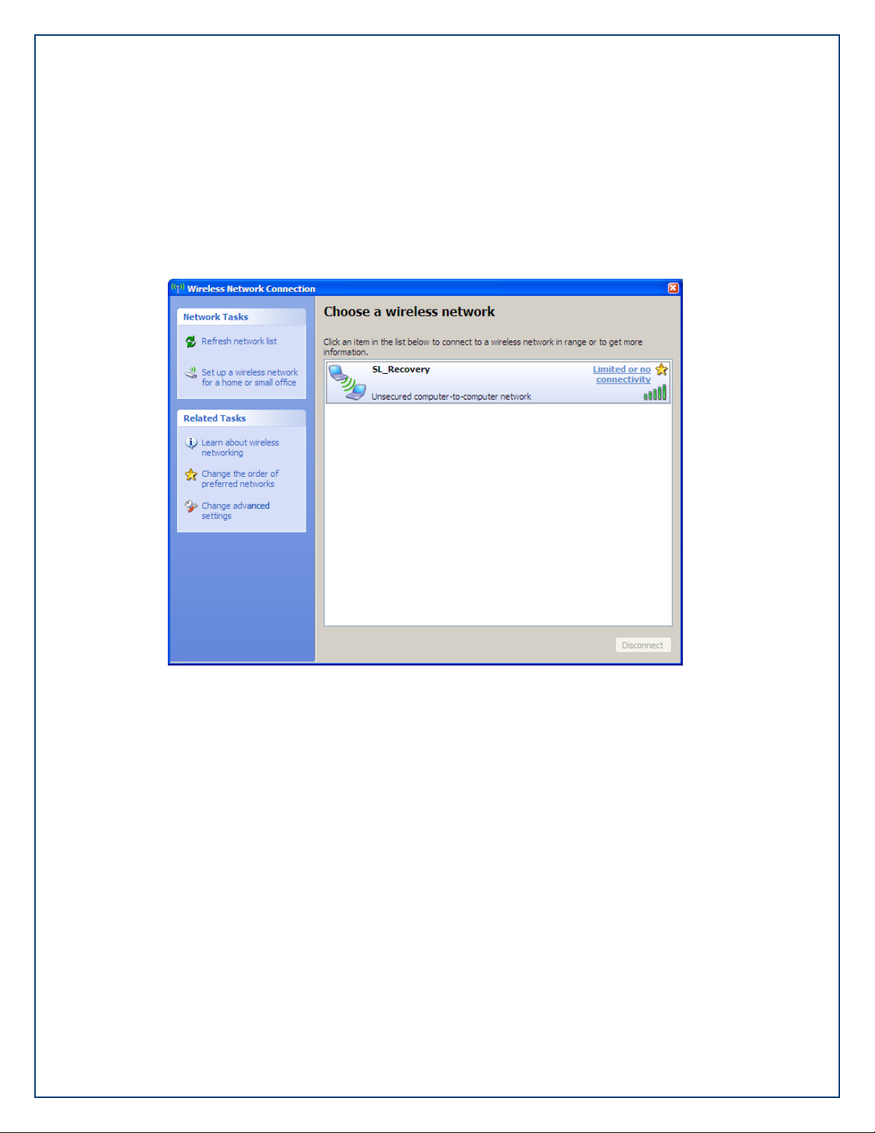
©Sealevel Systems, Inc.
SL9049 - 11/2010
SeaI/O Manual
58
The Wireless Network Connection window will now display “Limited or no connectivity” next to
the “SL_Recovery” network connection. All wireless SeaI/O modules are shipped with DHCP
enabled. When you first connect a wireless SeaI/O module to the network, the status LEDs on
the front of the module will blink while it searches for a DHCP server.
Since “SL_Recovery” is an Ad hoc point-to-point network and not on the same network as any
available DHCP servers, the SeaI/O module will not be able to complete the connection.
Close the Wireless Network Connection utility (you will still be directly connected to
“SL_Recovery”).
Page 59
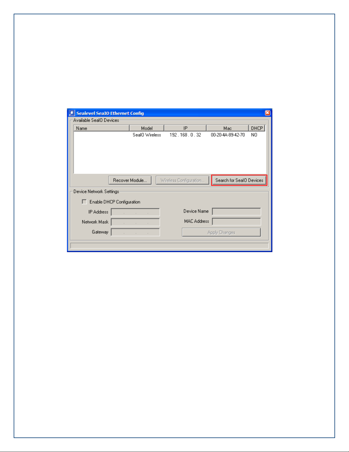
©Sealevel Systems, Inc.
SL9049 - 11/2010
SeaI/O Manual
59
Start the Ethernet Config utility (Start All Programs Sealevel SeaMAX Ethernet Config)
installed with SeaMAX. In the „Available SeaI/O Devices‟ pane, you should see a “SeaIO Wireless”
module listed under Model, as shown below.
If the module doesn‟t show up, click the “Search for SeaI/O Devices” button. The „Available
SeaI/O Devices‟ pane should refresh with any Ethernet or Wireless SeaI/O modules that are
found on the network.
At this point, since no DHCP server is available, the wireless SeaI/O module will default to a
random IP address in the range 192.168.0.x.
Notice that the „Name‟ is not displayed due to the wireless SeaI/O module residing on a
different subnet than your wireless adapter. Ethernet Config will mask the „Name‟ of SeaI/O
modules operating on a different subnet than the subnet you are currently using.
Take note of the IP Address of the wireless SeaI/O module listed in the „Available SeaI/O
Devices‟ pane. You will need this number in order to continue.
Also, make sure that the MAC Address shown matches the MAC Address on the label on the
bottom of the wireless SeaI/O module. If the MAC address doesn‟t match, contact technical
support for further assistance.
Close Ethernet Config before continuing.
Page 60

©Sealevel Systems, Inc.
SL9049 - 11/2010
SeaI/O Manual
60
You must now change the IP Address of your wireless adapter to match the subnet (first 3
octets) of the wireless SeaI/O module listed in Ethernet Config.
You can change your wireless adapter's IP Address by going to the Properties dialog for your
wireless adapter (Start Settings Network Connections). Right-click on your network adapter
and then select Properties from the menu. This opens the Wireless Network Connection
Properties window.
On the General tab, select „Internet Protocol (TCP/IP)‟, leave the box checked, and then click the
Properties button.
Before you change any settings in the following window, make a note of your original
settings. You will need to revert back to your original wireless adapter settings once you
have successfully configured the wireless SeaI/O module to work with your network.
Page 61

©Sealevel Systems, Inc.
SL9049 - 11/2010
SeaI/O Manual
61
In the Internet Protocol (TCP/IP) Properties window, click the radio button for „Use the following
IP Address‟. The first 3 octets of the IP address must match the IP address displayed for the
wireless SeaI/O module. The last octet must be different.
In this example, the last octet for the wireless SeaI/O module is 32 and we configured the last
octet for the wireless adapter to 55. Click the OK button in this window. Click the OK button
on the Wireless Network Connection Properties window.
Page 62
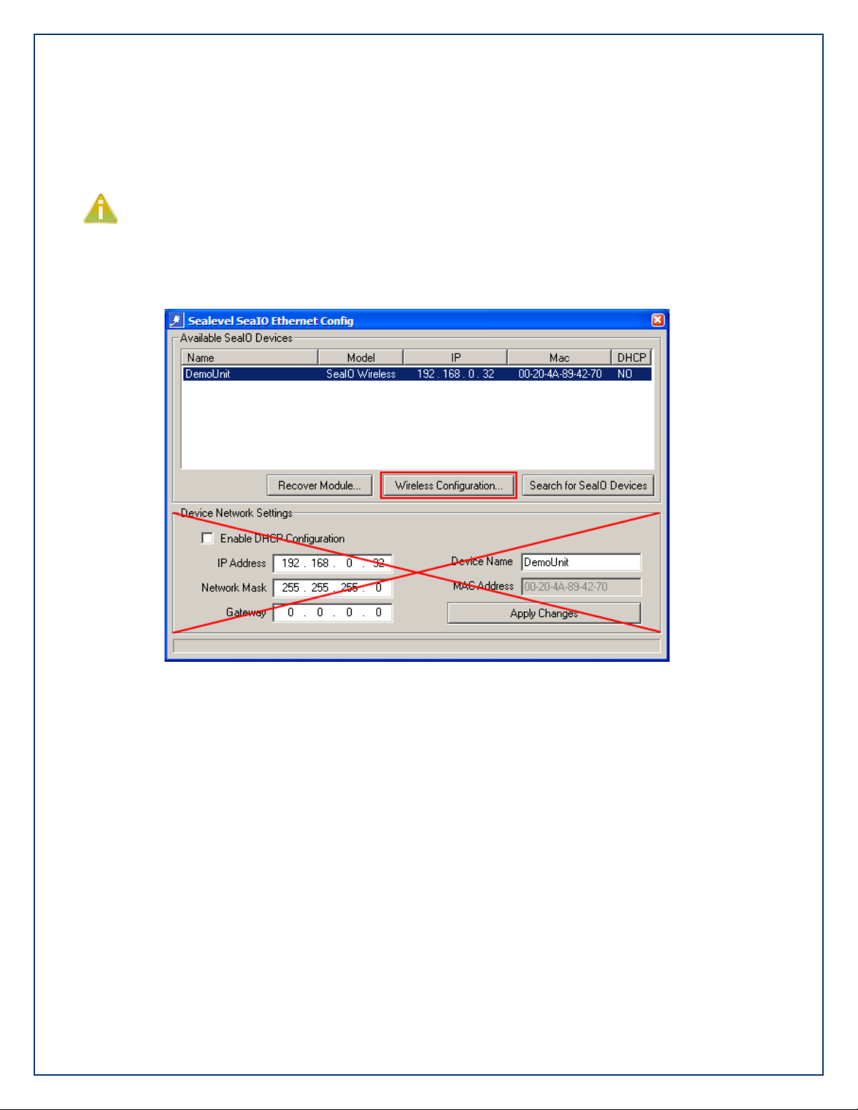
©Sealevel Systems, Inc.
SL9049 - 11/2010
SeaI/O Manual
62
To confirm that the IP Address for your wireless adapter was changed successfully, reopen
Ethernet Config (Start All Programs Sealevel SeaMAX Ethernet Config).
You should now see the wireless SeaI/O module‟s „Name‟ listed (“DemoUnit” in this example).
This indicates that your wireless adapter and the wireless SeaI/O module are on the same
subnet and you are now able to communicate with the wireless SeaI/O module.
Do not make any changes to the „Device Network Settings‟ at this point. You must complete
the Wireless Configuration first.
Verify that you can communicate with the wireless SeaI/O module by clicking the “Wireless
Configuration” button.
Page 63

©Sealevel Systems, Inc.
SL9049 - 11/2010
SeaI/O Manual
63
Now that you can communicate with the wireless SeaI/O module, the Wireless Configuration
settings window will open, as shown.
Page 64
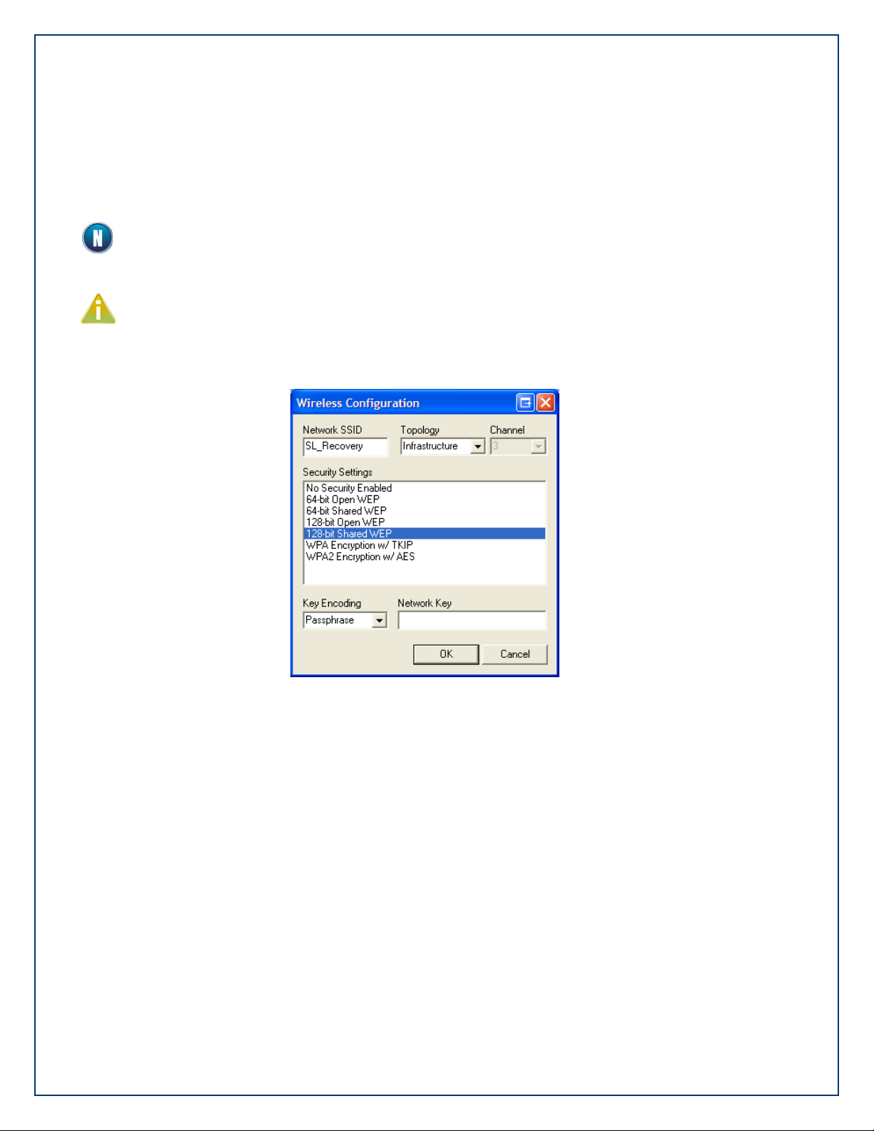
©Sealevel Systems, Inc.
SL9049 - 11/2010
SeaI/O Manual
64
You can now change the Network SSID, Topology, Channel, and Security Settings to match your
wireless network. After making your changes and clicking OK, the device will reboot and take
up to 20 seconds to appear on the network using your new settings. If you change the SSID
and/or network Topology and/or Channel, you‟ll have to reconnect to the SeaI/O module. Close
Ethernet Config for now.
The supported wireless configuration settings are detailed on the following page.
The Network SSID, wireless network channel, and security settings are specific to your
wireless network. Consult your IT department if you are unsure of your wireless network
settings.
Once you change the wireless configuration and click the OK button, the wireless SeaI/O
module will disappear from the Ethernet Config window. The SeaI/O module will now be
configured to work with your wireless network, but will likely be on a different subnet. You
still need to configure the Device Network Settings before the module will work with your
wireless network.
Page 65

©Sealevel Systems, Inc.
SL9049 - 11/2010
SeaI/O Manual
65
The following options are available in the Wireless Configuration window:
Wireless Configuration
Default Settings
Available Options
Network SSID
SL_Recovery
Alphanumeric
Case Sensitive
32 Characters
Topology
Ad Hoc
Ad Hoc
Infrastructure
Channel
[Varies]
1 – 11 (US)
1 – 14 (Europe, Japan)
Security Settings
(Ad Hoc Mode)
No Security Enabled
No Security Enabled
64-bit Open WEP
64-bit Shared WEP
128-bit Open WEP
128-bit Shared WEP
Security Settings
(Infrastructure Mode)
No Security Enabled
No Security Enabled
64-bit Open WEP
64-bit Shared WEP
128-bit Open WEP
128-bit Shared WEP
WPA Encryption w/ TKIP
WPA2 Encryption w/ AES
Key Encoding
Passphrase
Passphrase
Hexadecimal Key
Network Key
[None]
[See Next Page]
This information explains the various configuration options available. Continue with the
wireless SeaI/O configuration on the following page.
The Network SSID (Service Set Identifier) is the name of the wireless network. The SSID can be
up to 32 alphanumeric characters and is case-sensitive. If you are using the wireless SeaI/O
module with a wireless access point (WAP), then the SSID names must match.
The network Topology defaults to Ad Hoc mode and supports Infrastructure mode. Ad Hoc
mode is a point-to-point method used to communicate with other wireless network clients,
including laptop computers and desktop computers using a wireless adapter. If you are using a
WAP, select Infrastructure mode.
The network Channel will vary depending on the number of times the wireless SeaI/O module is
reset. Every time the wireless SeaI/O module is reset, the channel will increment up by one.
Since the wireless SeaI/O module supports channels 1-14, there is a chance that a reset can put
the wireless SeaI/O module on a channel not compatible with your wireless adapter or access
point. If you cannot see the wireless SeaI/O module on your network, try resetting the module
Page 66
©Sealevel Systems, Inc.
SL9049 - 11/2010
SeaI/O Manual
66
using the steps described at the beginning of this section. Depending on the country used, it
WEP 64-bit
10 character hexadecimal key or up to 32 character passphrase
WEP 128-bit
26 character hexadecimal key or up to 32 character passphrase
WPA
up to 64 character passphrase
WPA2
up to 64 character passphrase
may take several reset cycles to get the unit back to a channel valid for your region. Use the
Wireless Configuration window to change channels, if possible.
The Key Encoding method can be either a Passphrase or a Hexadecimal Key, if using a WEP
variant. If you are using a WPA variant, then the Key Encoding method is Passphrase.
Different security encryption methods require different Network Key types and lengths. The
different key types and lengths are displayed below:
Page 67
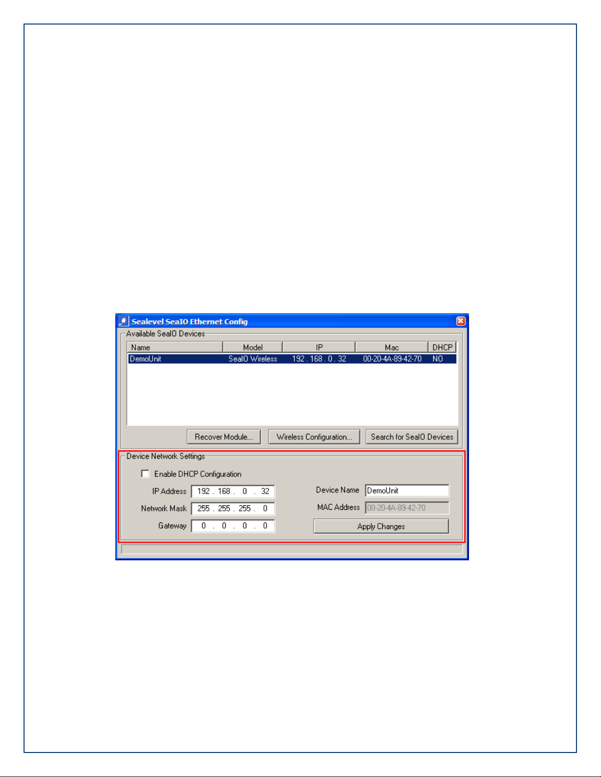
©Sealevel Systems, Inc.
SL9049 - 11/2010
SeaI/O Manual
67
Open the Wireless Network Connection utility again (Start right-click on My Network Places
select Properties from the menu. In the next window, right-click on your wireless network
connection select „View Available Wireless Networks‟ from the menu).
Select the SSID for your wireless network and click the “Connect” button. The wireless SeaI/O
module will no longer be visible since you configured it to work with your wireless network in
the previous step. You still need to configure the „Device Network Settings‟ in Ethernet Config
to complete the configuration of the wireless SeaI/O module.
Open Ethernet Config (Start All Programs Sealevel SeaMAX Ethernet Config). The
wireless SeaI/O module should appear in the „Available SeaI/O Devices‟ pane. Click on the
wireless SeaI/O module to select the device. The current settings now appear in the „Device
Network Settings‟ area.
If your wireless network is set up to use DHCP, click the „enable DHCP configuration‟ checkbox
and then click the „Apply Changes‟ button.
Otherwise, set the IP Address, Network Mask, and Gateway to match the settings for your
wireless network. You can change the „Device Name‟ to something appropriate for your
application. Click the „Apply Changes‟ button. The wireless SeaI/O module will again
disappear, but is now fully configured to work with your wireless network. Close the Ethernet
Config utility.
Page 68
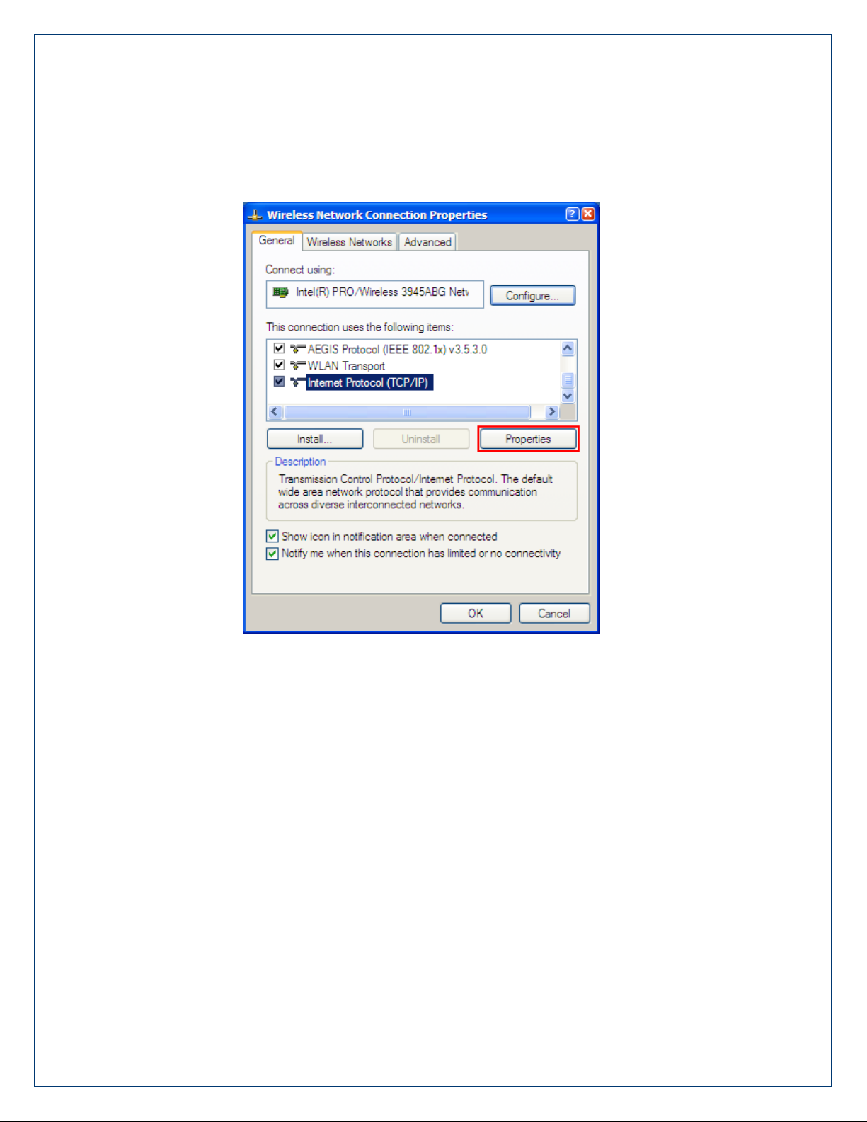
©Sealevel Systems, Inc.
SL9049 - 11/2010
SeaI/O Manual
68
To complete the configuration, you need to change the IP Address of your wireless adapter back
to its original settings. Open the Network Connections utility (Start Settings Network
Connections). Right-click on your network adapter and select Properties.
On the General tab, select „Internet Protocol (TCP/IP)‟, leave the box checked, and then click the
Properties button.
In the Internet Protocol (TCP/IP) Properties window, change the settings for your wireless
adapter back to the original settings you noted at the beginning on this section. Click the OK
button in this window. Click the OK button on the Wireless Network Connection Properties
window.
Your wireless adapter should now be configured for your wireless network and the wireless
SeaI/O module should now be properly configured to work with your wireless network. You can
open Ethernet Config to verify. If you have any problems, please contact Sealevel technical
support at support@sealevel.com.
Page 69
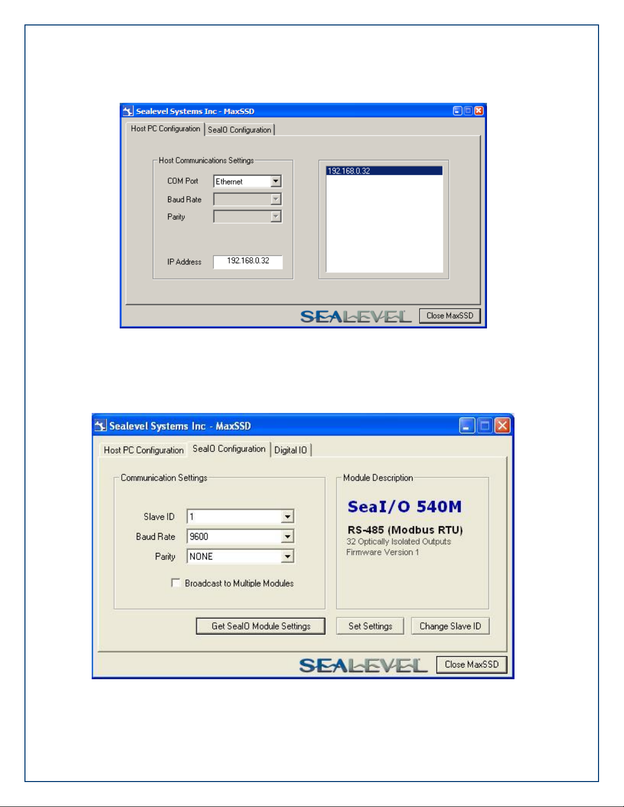
©Sealevel Systems, Inc.
SL9049 - 11/2010
SeaI/O Manual
69
Start MaxSSD (Start All Programs Sealevel SeaMAX MaxSSD) and select Ethernet in the
drop down box. Verify that the IP Address for the wireless SeaI/O module appears in the right
hand pane.
Choose the correct IP Address (if more than one is listed) and click the “SeaI/O Configuration”
tab. Use the drop down box to select the appropriate Slave ID (default is 247) and the click the
“Get SeaI/O Module Settings” button. You will see the description for the wireless SeaI/O
module appear in the right hand frame.
Page 70

©Sealevel Systems, Inc.
SL9049 - 11/2010
SeaI/O Manual
70
Set the slave ID of the “base” wireless SeaI/O module using the rotary switch or software
selection method discussed in the Setting Device Address section (MaxSSD chapter) of this
manual. This guarantees that any expansion modules connected next will not conflict with the
“base” module. Perform another Get operation to verify that you can communicate with the
“base” wireless SeaI/O module at the new slave ID.
Configure the SeaI/O modules one at a time. Set the address to a hardware slave ID other
than “0” or a software slave ID other than 247, to avoid device conflicts during setup.
After the “base” wireless SeaI/O module is successfully communicating via MaxSSD, you can
proceed with adding SeaI/O expansion modules (N-series). Refer to the Configuring Expansion
Modules section of this manual.
Page 71
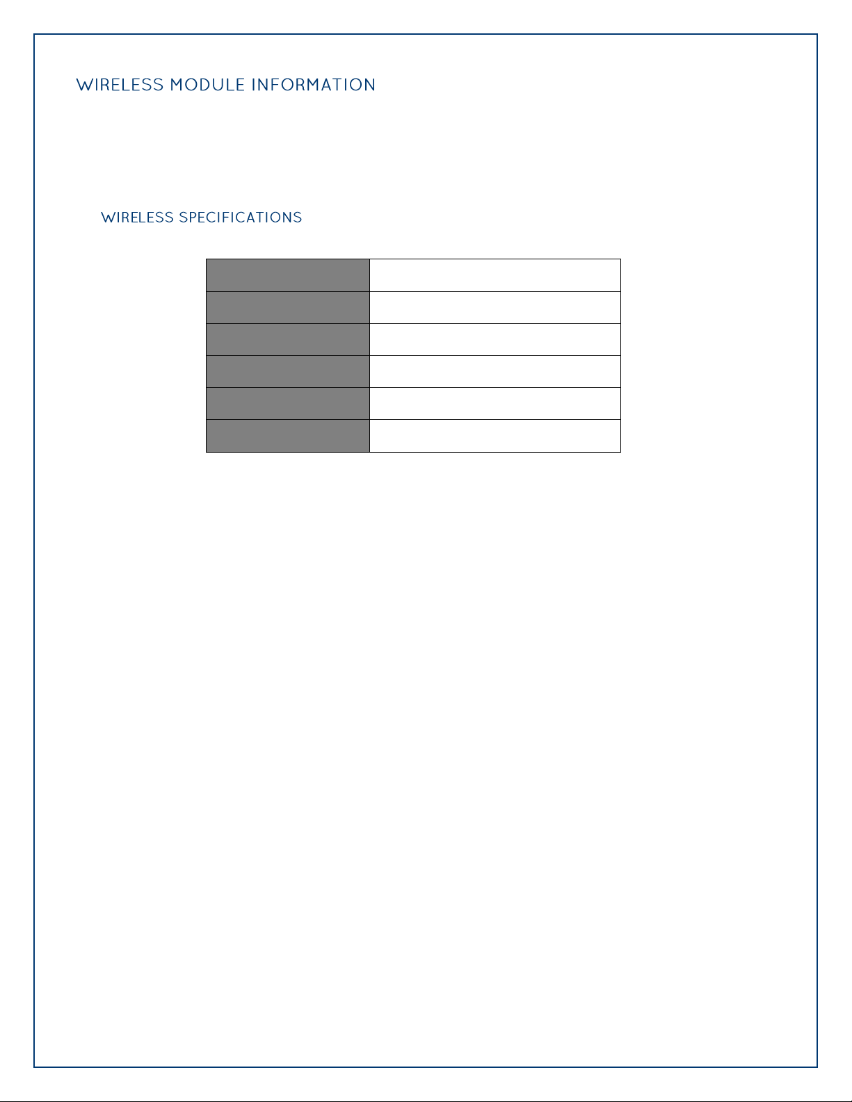
©Sealevel Systems, Inc.
SL9049 - 11/2010
SeaI/O Manual
71
SeaI/O wireless (W-series) modules are compatible with 802.11b and 802.11g wireless networking
Standards
802.11b, 802.11g, 802.11i
Channels
1-14
Frequency Range
2.412 – 2.484 GHz
Wireless Output Range
14 dBm +1.5/-1.0 dBm
Data Rates
54Mbps Max, 1Mbps Min
Range
328‟ (Indoors)
equipment operating in the 2.4GHz frequency spectrum. The wireless modules can operate over
any of the 14 available channels, defined by the IEEE 802.11 specification, listed by country below.
These regulations are subject to change at any time. Please consult your local regulatory authority
for current information.
Page 72
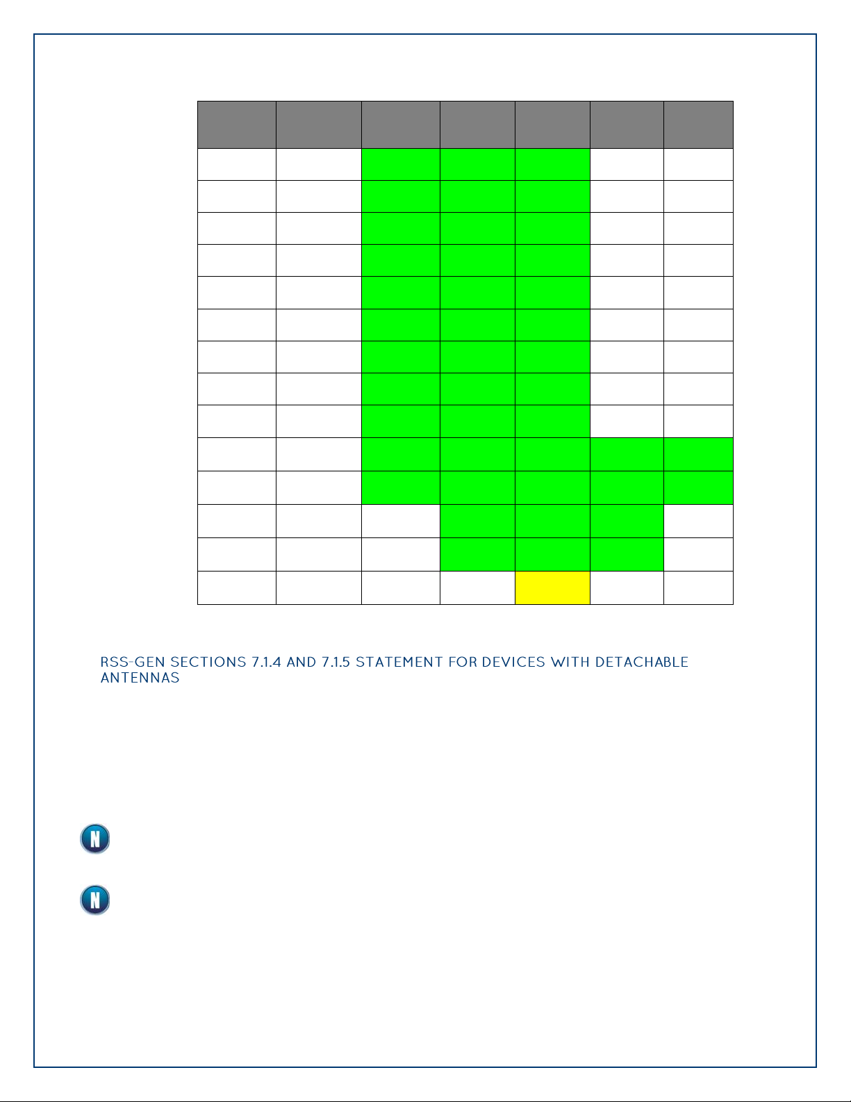
©Sealevel Systems, Inc.
SL9049 - 11/2010
SeaI/O Manual
72
Channel
Frequency
(GHz)
North
America
Europe
Japan
France
Spain
1
2.412
OK
OK
OK
No
No
2
2.417
OK
OK
OK
No
No
3
2.422
OK
OK
OK
No
No
4
2.427
OK
OK
OK
No
No
5
2.432
OK
OK
OK
No
No
6
2.437
OK
OK
OK
No
No
7
2.442
OK
OK
OK
No
No
8
2.447
OK
OK
OK
No
No
9
2.452
OK
OK
OK
No
No
10
2.457
OK
OK
OK
OK
OK
11
2.462
OK
OK
OK
OK
OK
12
2.467
No
OK
OK
OK
No
13
2.472
No
OK
OK
OK
No
14
2.484
No
No
802.11b
No
No
This device contains an FCC approved RF module. The transmitter carries FCC ID: R68WIPORTG.
This device has been designed to operate with the antennas listed in the Certificate, and having
a maximum gain of 5 dB. Antennas not included in this list or having a gain greater than 5 dB
are strictly prohibited for use with this device. The required antenna impedance is 50 ohms.
To reduce potential radio interference to other users, the antenna type and its gain should be
so chosen that the equivalent isotropically radiated power (EIRP) is not more than that required
for successful communication.
This module is authorized under limited module approval specified to mobile host
equipment. So, the antenna must be installed such that 20cm is maintained between the
antenna and users.
The transmitter module may not be co-located with any other transmitter or antenna.
Page 73

©Sealevel Systems, Inc.
SL9049 - 11/2010
SeaI/O Manual
73
This section applies only to Ethernet (E-series) SeaI/O modules. For all other SeaI/O
modules, refer to the Configuring a “Base” SeaI/O Module and Configuring Expansion
Modules sections on the previous pages.
Verify that SeaMAX software has been installed successfully and that an Ethernet SeaI/O module is
connected directly to your computer using the yellow crossover cable supplied with your module.
This module will become the “base” module.
All Ethernet SeaI/O modules are shipped with DHCP enabled. When you first connect an Ethernet
SeaI/O module to the network, the status LEDs on the front of the module will blink while it
searches for a DHCP server. Once it receives an IP address, the status LEDs will remain on.
If no DHCP server is available, the Ethernet SeaI/O module will default to a random IP address in the
range 169.254.x.x. To discover the SeaI/O module‟s IP address, start the Ethernet Config utility
(Start All Programs Sealevel SeaMAX Ethernet Config) installed with SeaMAX.
Click on the “Search for SeaI/O Devices” button and the „Available SeaI/O Devices‟ pane should
refresh with any Ethernet or Wireless SeaI/O modules that are found on the network. Select one of
the modules in the list by clicking on it. You can update the settings in the Device Network
Settings pane and then confirm these changes by clicking the “Apply Changes” button. The module
list should refresh, indicating that your changes were successful.
If the module does not change or respond, the PC and the module may be on different
subnets. Proceed to the Resetting An Ethernet SeaI/O Module section on the following
page.
Page 74
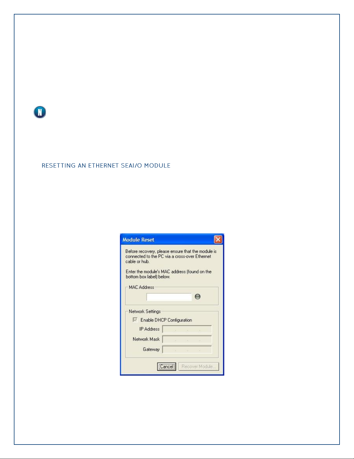
©Sealevel Systems, Inc.
SL9049 - 11/2010
SeaI/O Manual
74
Start MaxSSD (Start All Programs Sealevel SeaMAX MaxSSD) and choose the correct IP
address to communicate with the “base” Ethernet SeaI/O module. Ensure a successful Get
operation (refer to the MaxSSD section of this manual for more information).
Set the slave ID of the “base” Ethernet SeaI/O module using the rotary switch or software selection
method discussed in the Setting Device Address section on the previous pages. This guarantees
that any expansion modules connected next will not conflict with the “base” module. Perform
another Get operation to verify that you can communicate with the “base” Ethernet SeaI/O module
at the new slave ID.
Configure the SeaI/O modules one at a time. Set the address to a hardware slave ID other
than “0” or a software slave ID other than 247, which avoids device conflicts during setup.
After the “base” Ethernet SeaI/O module is successfully communicating via MaxSSD, you can
proceed with adding SeaI/O expansion modules (N-series). Refer to the Configuring Expansion
Modules section on the previous pages.
An Ethernet SeaI/O module may become no longer visible in the module list in the Ethernet
Config utility if the Ethernet SeaI/O module has been configured to use a different subnet than
the host computer.
In other cases, the Ethernet SeaI/O module doesn‟t appear in the module list due to a DHCP
discovery failure. In either case, clicking on the “Recover Module” button (see image on
previous page) in the Ethernet Config utility will bring up the “Module Reset” window shown
below.
Page 75

©Sealevel Systems, Inc.
SL9049 - 11/2010
SeaI/O Manual
75
Before recovery begins, make certain that the PC and Ethernet SeaI/O module are on the same
network segment – they should be connected with an Ethernet crossover cable, through a hub,
or through a non-routing switch. Ethernet SeaI/O modules are shipped with both an Ethernet
patch cable (blue) and an Ethernet crossover cable (yellow).
Enter the MAC address found on the label on the bottom of the SeaI/O enclosure. A MAC
address is made up of six pairs of hex digits separated by dashes (i.e., xx-xx-xx-xx-xx-xx).
While entering the MAC address, the indicator to the right of the field will turn red if the MAC
address entered is invalid. Once a MAC address is successfully entered, the indicator light will
turn green and the “Network Settings” options will be enabled.
Contact your network administrator if you are unsure of the proper network settings to choose.
If a DHCP server is available, select the “Enable DHCP Configuration” checkbox. Otherwise,
complete the network settings and click the “Recover Module” button to complete the
configuration changes.
Proceed with configuring expansion modules, explained in the previous section.
Page 76

©Sealevel Systems, Inc.
SL9049 - 11/2010
SeaI/O Manual
76
The initial version of the firmware does not support theses Advanced Features. These units will
report their version number as “1”. Starting with version “2” support for these Advanced
Features was implemented. You may determine the version of your SeaIO device using the
MODBUS command FUNC_SEAMAX_GET_EXTENDED_INFO (0x66), or by viewing the device info
in MaxSSD, shown below.
In addition, the following modules do not support the Advanced Features:
462
463
470
In the event that a newer version of the firmware is available, it is possible to upgrade the
firmware in the unit. This can be done through the same port that is used to do normal
communications with the unit. The exception is when the unit is used with a wireless
connection. In this case, the unit must be directly connected to the programming computer.
Since there is required interaction between the programming PC and the SeaIO module being
programmed, this must be done in a situation where only one SeaIO module is connected to the
programming computer.
Once you have the new programming file – this will be a file with a name similar to your SeaIO
model number with an extension of “.hex”. As an example, it you have a SeaIO 420 style
module, the programming file name would be “420E.hex”.
When you are provided the file to be programmed, you will also receive the programming
program. The name of this program is SeaIOCU.exe.
Page 77

©Sealevel Systems, Inc.
SL9049 - 11/2010
SeaI/O Manual
77
Since SeaIOCU.exe must be executed from a command prompt, the easiest way to use it is to
copy SeaIOCU.exe and the hex file (in this example it is 420E.hex) to a subdirectory you create.
For this example, we will create a subdirectory called c:\seaiocu.
Click on Start, then click Run and type “cmd” (without the quotation marks and hit enter. You
will then see a command prompt (c:\documents and settings\name>).
Type
Cd \seaiocu and then press Enter
At this point, we assume the SeaIO 420 unit is set for 9600 baud and address 247 (the default
if the rotary switch is in position 0).
If you are connected either through a RS-232, RS-485, or USB connection then when the
command calls for nnn you substitute you com port number. Note that it MUST be 3 digits.
Therefore, if your com port is com5, you will enter 005. The command for this is therefore:
Seaiocu /c=005 /b=9600 /a=247 420e.hex
If you are connected through an Ethernet connection then when the command calls for
iii.iii.iii.iii you substitute the unit‟s IP address. Note that each group of numbers MUST be 3
digits. Therefore, if your IP address is 192.168.42.11, you will enter 192.168.042.011. The
command for this is therefore:
Seaiocu /i=192.168.042.011 /a=247 420e.hex
The first thing the SeaIO unit will do is to erase all of its flash memory (with the exception of a
small loader for the firmware). It will then start flashing all three lights rapidly indicating it
requires downloading. Once the download starts, one light will flash as data is downloaded.
Once the download is complete, the green light will remain on. At this point, simply unplug
power to the unit and when power is re-applied, you should be operational with the new
software.
In the event something about the download failed, the red light should stay on. In this case,
simply power down the unit and power it back up. It should now be flashing all three lights
rapidly. Simply perform the seaiocu command as described above.
The above should only be performed if you (1) really feel the update is required and (2)
you feel confident in your ability to perform the update. Once the firmware has been
erased, you must either be able to re-program it locally or send it back to SeaLevel
Systems, Inc. for reprogramming.
Page 78

©Sealevel Systems, Inc.
SL9049 - 11/2010
SeaI/O Manual
78
Disabling the Rotary Address Switch and Limiting Software Address Range Selection is not
available on older SeaI/O units (Before Firmware Version 2). In addition, the following
modules do not support it:
462
463
470
As noted earlier, rotating the rotary switch from a non-zero address to the address zero
position will reset the unit to the default state of address 247 and 9600 baud. There are many
situations where this is not desirable. In the event you wish to disable the rotary switch or
simply limit the range of software selectable addresses that may be set, you can do so by
sending the “WriteMultipleRegisters (function 0x16)” MODBUS command to the unit. Address
300 (decimal) should contain the low order byte of the lowest address the unit will accept.
Address 301 will contain the high order byte. Once this command has been issued, the rotary
switch will be completely ignored by the firmware.
To reset the unit to “normal” operation, you can issue the MODBUS “Broadcast Reset Message
(function 0x19).
This setting can also be configured through MaxSSD under the “Range Configuration” tab,
shown below on the next page.
Page 79
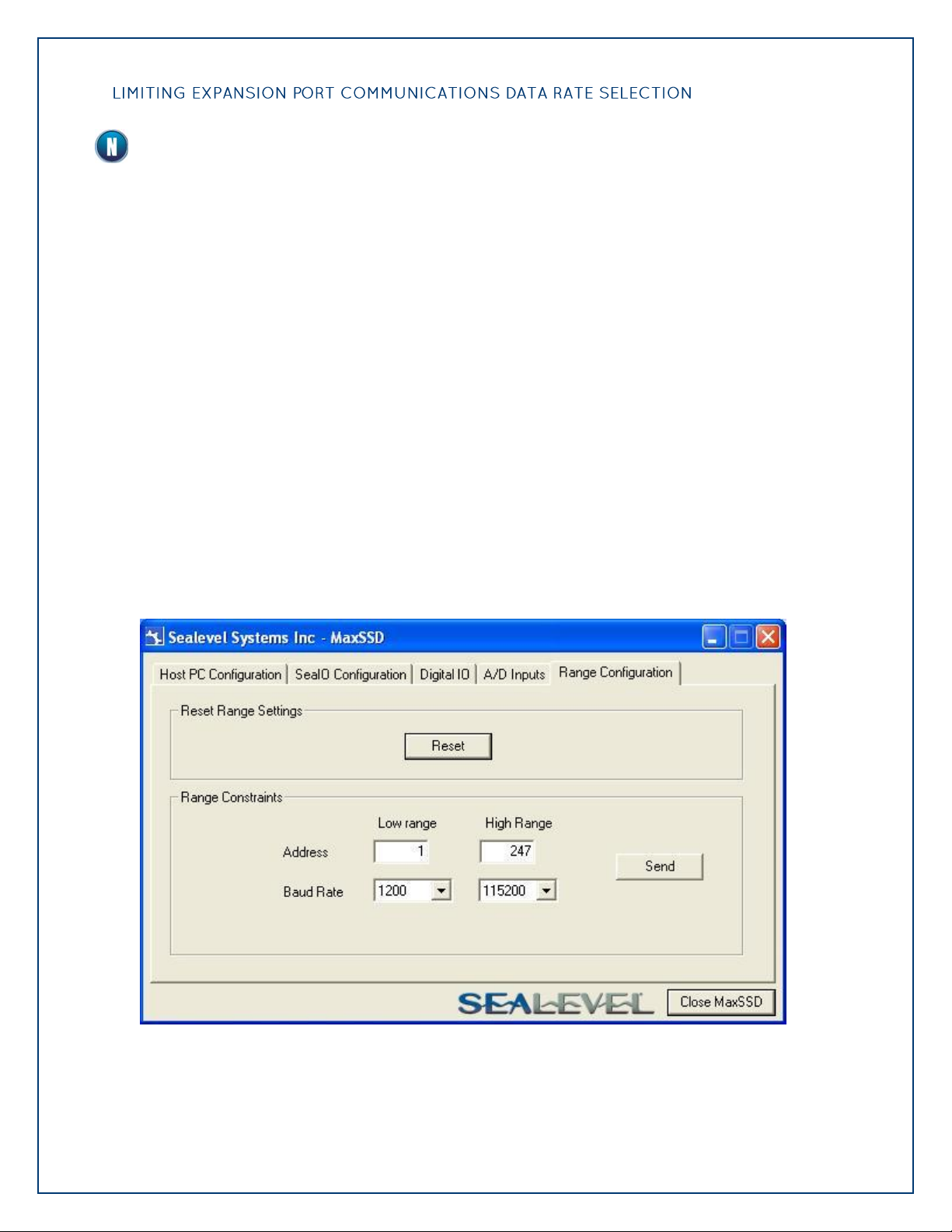
©Sealevel Systems, Inc.
SL9049 - 11/2010
SeaI/O Manual
79
Limiting Expansion Port Communications Data Rate Selection is not available on older
SeaI/O units (Before Firmware Version 2). In addition, the following modules do not support
it:
462
463
470
There are situations where it is desirable to limit the range of allowable data rates or lock down
the unit to one specific data rate. This can be performed by sending the “WriteMultipleRegisters
(function 0x16)” MODBUS command to the unit. Address 302 (decimal) should contain the low
order byte of the lower data rate the unit will accept. Address 303 will contain the high order
byte. Note that this command does not cause the rotary switch to be ignored. Therefore, the
rotary switch can be used to reset the defaults range and set the data rate back to 9600. If this
is not desirable, then you can either set the data rate limitation and then set the address range
to prevent the rotary switch from resetting to defaults or you can write to locations 300 through
303 in one “WriteMultipleRegisters” command.
To reset the unit to “normal” operation, you can issue the MODBUS “Reset Range Settings”
(function 0x19).
This setting can also be configured through MaxSSD under the “Range Configuration” tab,
shown below.
Page 80
©Sealevel Systems, Inc.
SL9049 - 11/2010
SeaI/O Manual
80
A copy of these instructions is included with the SeaI/O-463 module and can also be downloaded
from the SeaI/O-463 product page on the Sealevel website.
Do not perform these instructions with the power connected. Be sure to follow proper ESD
procedures by grounding yourself and the SeaI/O module.
SeaI/O-463 module
Phillips head screwdriver
Slotted screwdriver
50-pin IDC ribbon cable* (up to four)
CA167 – 40” IDC 50-pin to IDC 50-pin ribbon cable
CA197 – 18” IDC 50-pin to IDC 50-pin ribbon cable
CA135 – 40” IDC 50-pin to 50-pin edge connector ribbon cable
Page 81
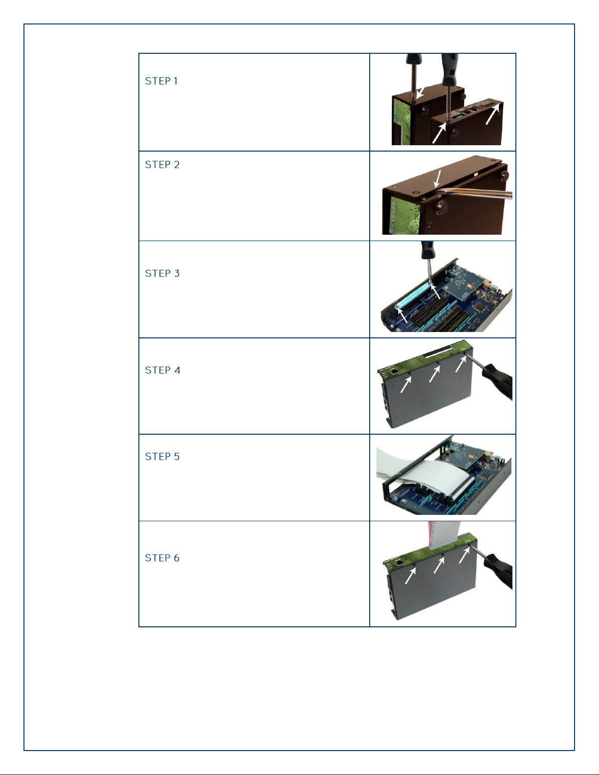
©Sealevel Systems, Inc.
SL9049 - 11/2010
SeaI/O Manual
81
Remove the terminal block from the left side and
then remove the two black screws from each side
of the module as shown in the image.
On the front right side of the module, wedge a
slotted screwdriver between the top and bottom
halves as shown. Pry upwards – a pem in the top
half must clear the metal lip in the bottom half of
the enclosure.
Remove the two screws from the metal strain
relief, as shown.
Remove the three screws from the bottom of the
module and remove the front plate.
Install up to four industry standard ribbon cables
in the 50-pin header connectors. A list of optional
cable part numbers is listed on the previous page.
Replace the front plate and install the three screws
in the bottom of the module as shown.
Page 82

©Sealevel Systems, Inc.
SL9049 - 11/2010
SeaI/O Manual
82
Replace the metal strain relief. Start both screws
and tighten only until snug. Do not over-tighten.
Replace the top half by starting it on the left side
over the connectors and then snapping the right
side down into place. Be careful not to pinch
fingers. Replace both screws on each side and
then replace the terminal block on the left side.
Continue with the installation of the SeaI/O-463
module. The SeaI/O Hardware Description section
of this manual contains information on TTL
applications and optional accessories. The SeaMAX
Application Suite section walks you through setting
up the hardware address (Slave ID) and software
installation.
Page 83
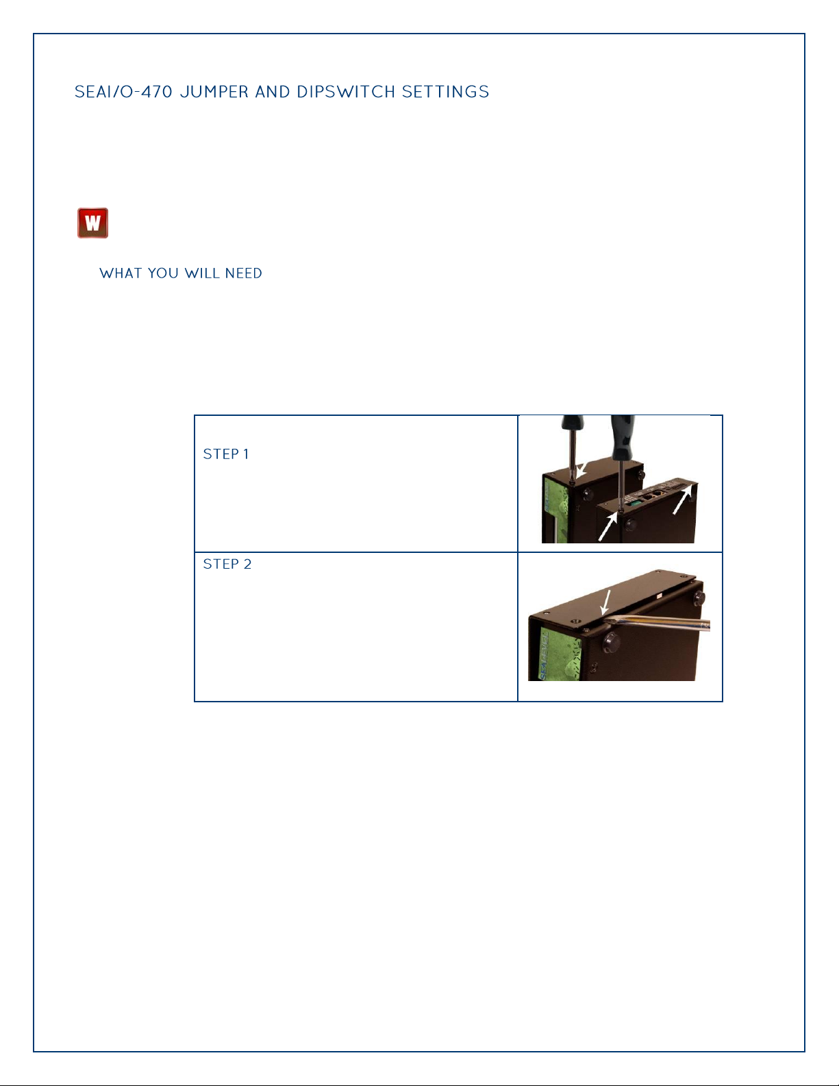
©Sealevel Systems, Inc.
SL9049 - 11/2010
SeaI/O Manual
83
The SeaI/O-470 module ships factory configured with the D/A outputs set for 0-10V and current
Remove the terminal block from the left side and
then remove the two black screws from each side
of the module as shown in the image.
On the front right side of the module, wedge a
slotted screwdriver between the top and bottom
halves as shown. Pry upwards – a pem in the top
half must clear the metal lip in the bottom half of
the enclosure.
Jumpers and dipswitch locations are shown on the
following page.
loop mode on the A/D inputs disabled. If you need to enable current loop mode or set the D/A
outputs to 0-5V, you will need to open the enclosure and access the jumpers (shown on the next
page).
Do not perform these instructions with the power connected. Be sure to follow proper ESD
procedures by grounding yourself and the SeaI/O module.
SeaI/O-470 module
Phillips head screwdriver
Slotted screwdriver
Page 84
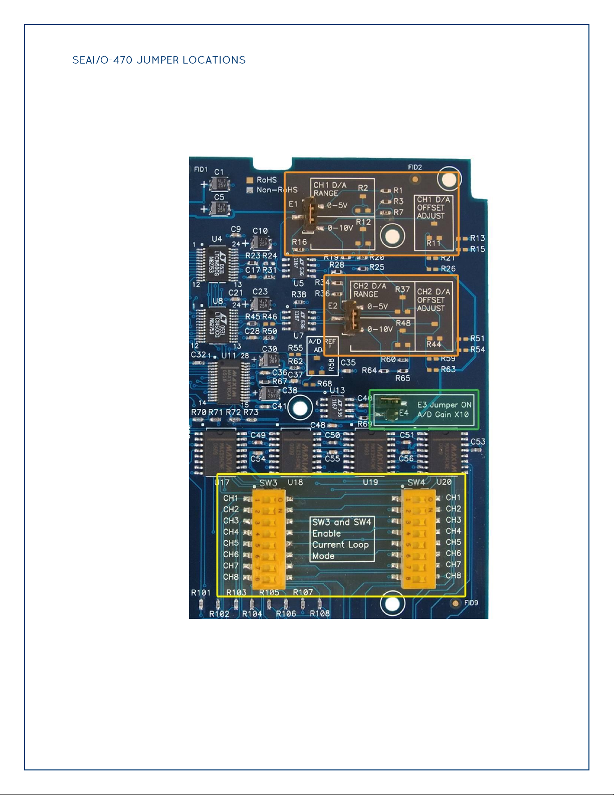
©Sealevel Systems, Inc.
SL9049 - 11/2010
SeaI/O Manual
84
This detail image of the right side of the SeaI/O-470 circuit board shows the locations of the
user configurable jumpers and dipswitches. Refer to the following pages for instructions on
properly configuring the jumpers and switches. The colored boxes are shown here for clarity
and are not visible on the actual circuit board.
Page 85

©Sealevel Systems, Inc.
SL9049 - 11/2010
SeaI/O Manual
85
The (E1) and (E2) jumpers (shown in the orange boxes on the previous page) configure the D/A
outputs for 0-5V or 0-10V. Both channels can be configured independently. The D/A outputs
do not support negative voltages. You must also set the correct output voltage in your
application or MaxSSD. Refer to the SeaMAX Application Suite section of this manual for help
configuring software to work with the SeaI/O-470.
The A/D 10X gain (E3) jumper (shown in the green box on the previous page) is disabled at the
factory. Position the hardware jumper on both pins to enable this functionality, which allows
smaller voltages to be measured more accurately (e.g., a 0-1V input signal can be measured
more accurately by enabling the 10x hardware gain jumper and setting the SeaI/O-470 A/D
input channel for 0-10V range). You can also set the A/D input channel for 0-5V to sense
voltages smaller than 0.5V.
When the jumper is enabled, the “10X Hardware Gain” checkbox will also be enabled on the A/D
Inputs tab in MaxSSD. Refer to the SeaMAX Application Suite section of this manual for
information on using MaxSSD.
The (SW3) and (SW4) dipswitches (shown in the yellow box on the previous page) configure the
A/D inputs for current loop mode and are disabled at the factory. Since current loop mode is
differential, the corresponding dipswitch on both (SW3) and (SW4) should be properly set (e.g.,
„CH1‟ on both dipswitches needs to be set to „ON‟ to enable current loop mode).
SW3 – enables the current-loop sensing resistor
SW4 – ties the other half of connection to ground
Page 86
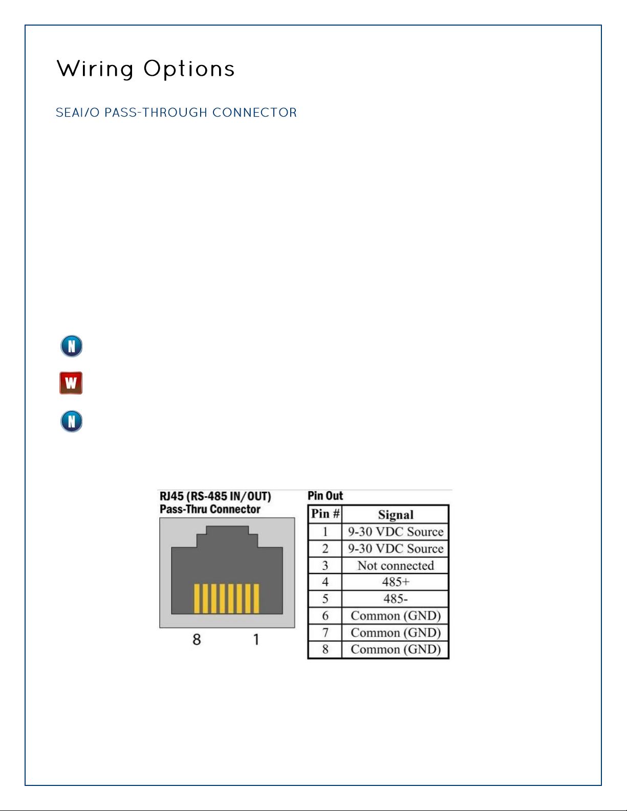
©Sealevel Systems, Inc.
SL9049 - 11/2010
SeaI/O Manual
86
All SeaI/O modules include two RS-485 pass-through connectors on the left side of the unit that are
internally connected to the same pins on the screw terminals. This offers two convenient options
for adding additional expansion modules.
For connecting several SeaI/O modules together in a “stack”, all N-series expansion modules ship
with an expansion and strap kit (Part# KT122) that includes four metal straps, four #4-40 screws,
and a 5” RJ45 RS-485 interconnect cable (Part# CA239). The metal straps allow you to securely
connect multiple SeaI/O modules together. The interconnect cable can be used to connect SeaI/O
modules together via the RJ45 pass-through connectors, providing an easy method to cascade RS485 signals and power from one module to the next.
For expansion modules that are less than ten feet from a base unit, a standard RJ45 CAT5 patch
cable (“straight-through”) may be used. For SeaI/O modules greater than ten feet apart, use
twisted-pair cable connecting the data lines to the screw terminals instead. If RJ45 connectors are
preferred, be sure to connect only the data lines (pins 4 and 5).
When using standard CAT5 patch cables to connect modules less than ten feet apart, ensure
the cables are wired “straight-through.”
Do not connect network crossover cables to the pass-through connectors, else damage to
equipment may result.
Modules greater than ten feet apart must have separate power supplies. Refer to the Power
Options section of this manual for recommendations.
Page 87

©Sealevel Systems, Inc.
SL9049 - 11/2010
SeaI/O Manual
87
Optically isolated inputs are arranged such that each group of four shares a single common.
The four I/O points and shared common are connected via a five-position removable screw
terminal. Input voltage range is 5-30VDC. Like the inputs, each group of four Reed relays also
shares a single common and connects via a five-position removable screw terminal. Form C
Relay outputs are arranged such that each group of two relays shares a common. The NC and
NO contacts of each relay along with the common are brought out via a five-position removable
screw terminal.
Page 88

©Sealevel Systems, Inc.
SL9049 - 11/2010
SeaI/O Manual
88
The SeaI/O-462 and SeaI/O-463 use 74ABT245 octal bi-directional transceivers to provide TTL
Bits 1-48
Bits
A1
B1
C1
A2
B2
C2
D0
75
38
18
10
30
2
D1
76
37
17 9 29
1
D2
77
36
16 8 28
22
D3
78
35
15 7 27
21
D4
59
34
14 6 26
40
D5
39
33
13 5 25
60
D6
20
32
12 4 24
61
D7
19
31
11 3 23
62
Bits 49-96
Bits
A3
B3
C3
A4
B4
C4
D0
75
38
18
10
30
2
D1
76
37
17 9 29
1
D2
77
36
16 8 28
22
D3
78
35
15 7 27
21
D4
59
34
14 6 26
40
D5
39
33
13 5 25
60
D6
20
32
12 4 24
61
D7
19
31
11 3 23
62
input/output capabilities and can sink 64mA and source 32mA. Each bit is pulled to +5V through a
10K ohm pull-up resistor to insure each bit is at a known state when not driven. The maximum
output power is +5V @ 1A (5W).
The SeaI/O-462‟s 96 digital I/O channels are brought out to two DB-78 Female connectors on
the front of the enclosure (pinout shown below). Each connector provides 48 bits of digital I/O
divided into six eight-bit ports. Each port may be individually configured via software command
as an input or an output.
Page 89

©Sealevel Systems, Inc.
SL9049 - 11/2010
SeaI/O Manual
89
Power & Commons
+5V
63, 74
Commons
41 – 58, 64 – 73
Page 90
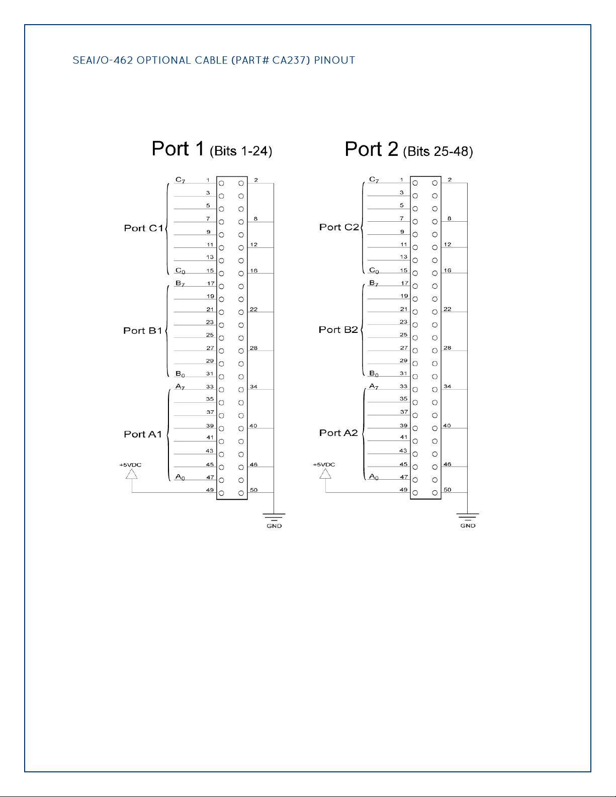
©Sealevel Systems, Inc.
SL9049 - 11/2010
SeaI/O Manual
90
For easy connection to industry-standard solid-state relay racks, Sealevel manufactures a 6‟
cable, Part# CA237, that terminates the DB-78 to two industry standard 50-pin header
connectors. Two cables and a SeaI/O unit can be order together as a kit using Part# 462x-KT.
The pinout for the two 50-pin headers is shown below.
Page 91
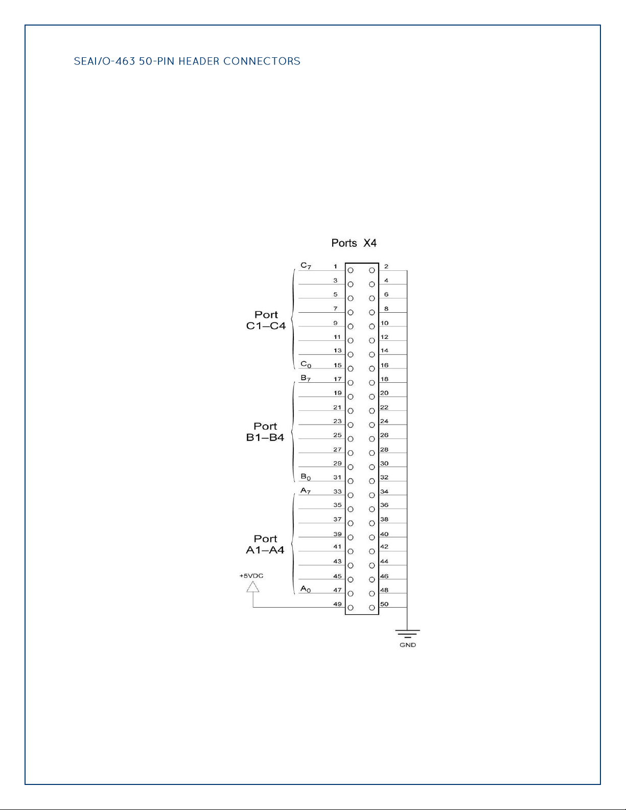
©Sealevel Systems, Inc.
SL9049 - 11/2010
SeaI/O Manual
91
The SeaI/O-463‟s 96 digital I/O channels are accessed via four industry-standard 50-pin header
connectors. Each header provides 24 bits of digital I/O divided into three eight-bit ports. Each
port may be individually configured via software command as an input or an output.
You will need to open the SeaI/O-463‟s enclosure to access the four header connectors: P2, P3,
P4, and P5. The connector designators are silk-screened onto the PCB for easy identification.
Once cables are connected to the headers, route them through the opening in the front of the
enclosure, attach the included strain-relief bracket to secure the cables and reassemble the
enclosure. Refer to the ribbon cable installation instructions included with the SeaI/O-463.
Each of the four 50-pin connectors has the following pinout, which is compatible with a wide
variety of industry-standard solid-state relay racks:
Page 92

©Sealevel Systems, Inc.
SL9049 - 11/2010
SeaI/O Manual
92
The SeaI/O-470 supports single-ended, differential, and current loop A/D inputs. Single-ended
and differential modes can be configured in software. Current loop mode requires configuring
dipswitches inside the enclosure. Refer to the Hardware Configuration section of this manual
for instructions on configuring the current loop dipswitches.
The SeaI/O-470 can be configured for up to sixteen 12-bit single-ended A/D inputs. Each input
is referenced to a common ground. The user selectable voltage ranges are 0-5V, 0-10V, +/-5V,
and +/-10V.
The SeaI/O-470 can be configured for up to eight 12-bit differential A/D inputs. The inputs are
not referenced to ground. The user selectable voltage ranges are 0-5V, 0-10V, +/-5V, and +/10V.
Page 93

©Sealevel Systems, Inc.
SL9049 - 11/2010
SeaI/O Manual
93
The SeaI/O-470‟s A/D channels can also be configured to provide up to eight 12-bit current
loop inputs. Each input has two terminals – one positive and one negative. The input current
range is 0-20mA for interfacing commonly used 4-20mA devices. The dipswitches inside the
enclosure must be properly configured for each current loop input.
The SeaI/O-470 provides two 12-bit D/A output channels, configured for 0-10V.
0-5V mode requires different jumper settings inside the enclosure. Refer to the Hardware
Configuration section of this manual for instructions on configuring the D/A jumpers.
The SeaI/O-470 module‟s D/A output channels can be independently configured for 0-5V or 010V. The D/A outputs do not support negative voltages.
Page 94
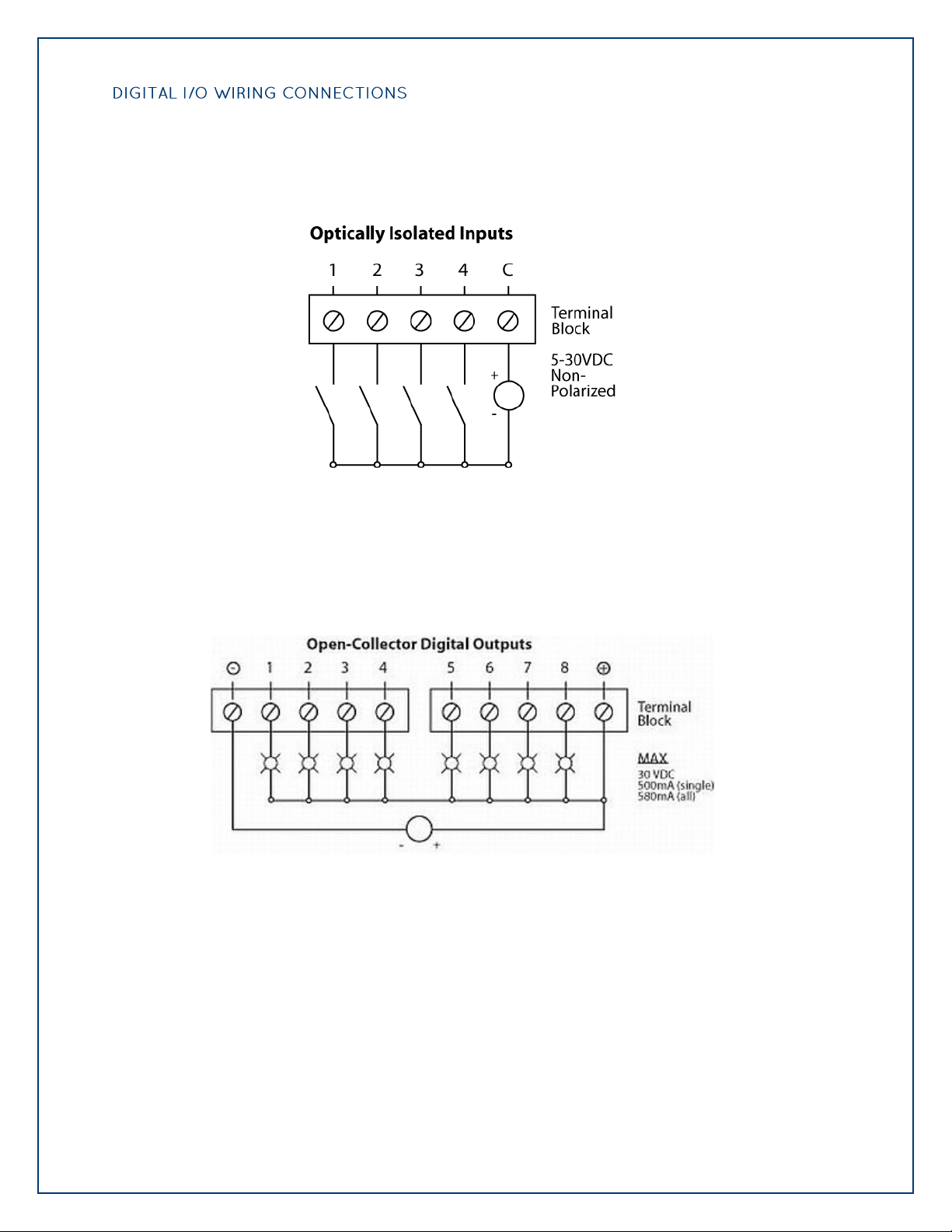
©Sealevel Systems, Inc.
SL9049 - 11/2010
SeaI/O Manual
94
The SeaI/O-470 modules include eight optically isolated inputs that are arranged such that each
group of four inputs shares a single common. The four I/O points and shared common are
connected via a five-position removable screw terminal.
The SeaI/O-470 modules provide eight open-collector digital outputs. The outputs do not
source any current and must be connected to an external power source, max 30VDC. The
outputs act as a switch and the circuit is open until energized. When the output circuit is
energized in software, the output sinks the current to ground, closing the circuit.
Page 95

©Sealevel Systems, Inc.
SL9049 - 11/2010
SeaI/O Manual
95
Optically isolated inputs are arranged such that each group of two shares a single common. The
four I/O points and shared common are connected via a six-position removable screw terminal.
Input voltage range is 5-30VDC. Like the inputs, each group of two Form C relays also shares a
single common. The NC and NO contacts of each relay along with the commons are brought
out via a six-position removable screw terminal.
Page 96
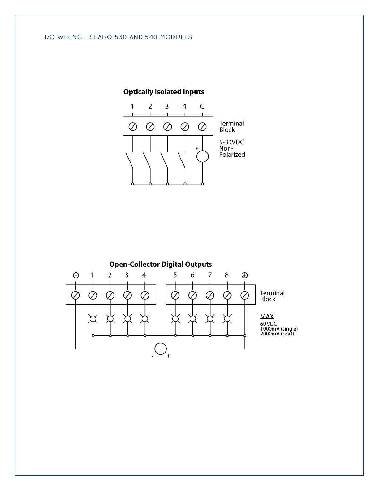
©Sealevel Systems, Inc.
SL9049 - 11/2010
SeaI/O Manual
96
The SeaI/O-530 modules include 16 optically isolated inputs that are arranged such that each
group of four inputs shares a single common. The four I/O points and shared common are
connected via a five-position removable screw terminal.
The SeaI/O-530 and 540 modules provide 16 or 32 open-collector outputs. The outputs do not
source any current and must be connected to an external power source, max 60VDC, through
the Vin pin locations. Each output acts as a switch and the circuit is open until energized. When
the output circuit is energized in software, the output sinks the current to ground, closing the
circuit.
Page 97

©Sealevel Systems, Inc.
SL9049 - 11/2010
SeaI/O Manual
97
SeaI/O S-Series (RS-232) modules have an RJ45 connector on the face of the enclosure. Each Sseries module includes a kit (Part# KT119) to convert the RJ45 RS-232 pin out to a standard DB9
RS-232 pin out. The kit ships with a DB-9F to RJ45 modular adapter (Part# DB109) with RS-232
pin out and a standard 7' CAT5 patch cable (Part# CA246). This kit allows SeaI/O S-series
modules to be easily connected to a standard DB9 RS-232 serial port. For other interfacing
options, the RJ45 serial pin out is shown below.
For SeaI/O S-series modules, pin 4 of the RJ45 connector outputs 5VDC @300mA. This is
useful for powering the wireless Bluetooth adapter (Sealevel Part# BT-SD100). This allows
any Bluetooth capable host to access a SeaI/O module as easily as communicating with a
standard RS-232 serial port.
Page 98
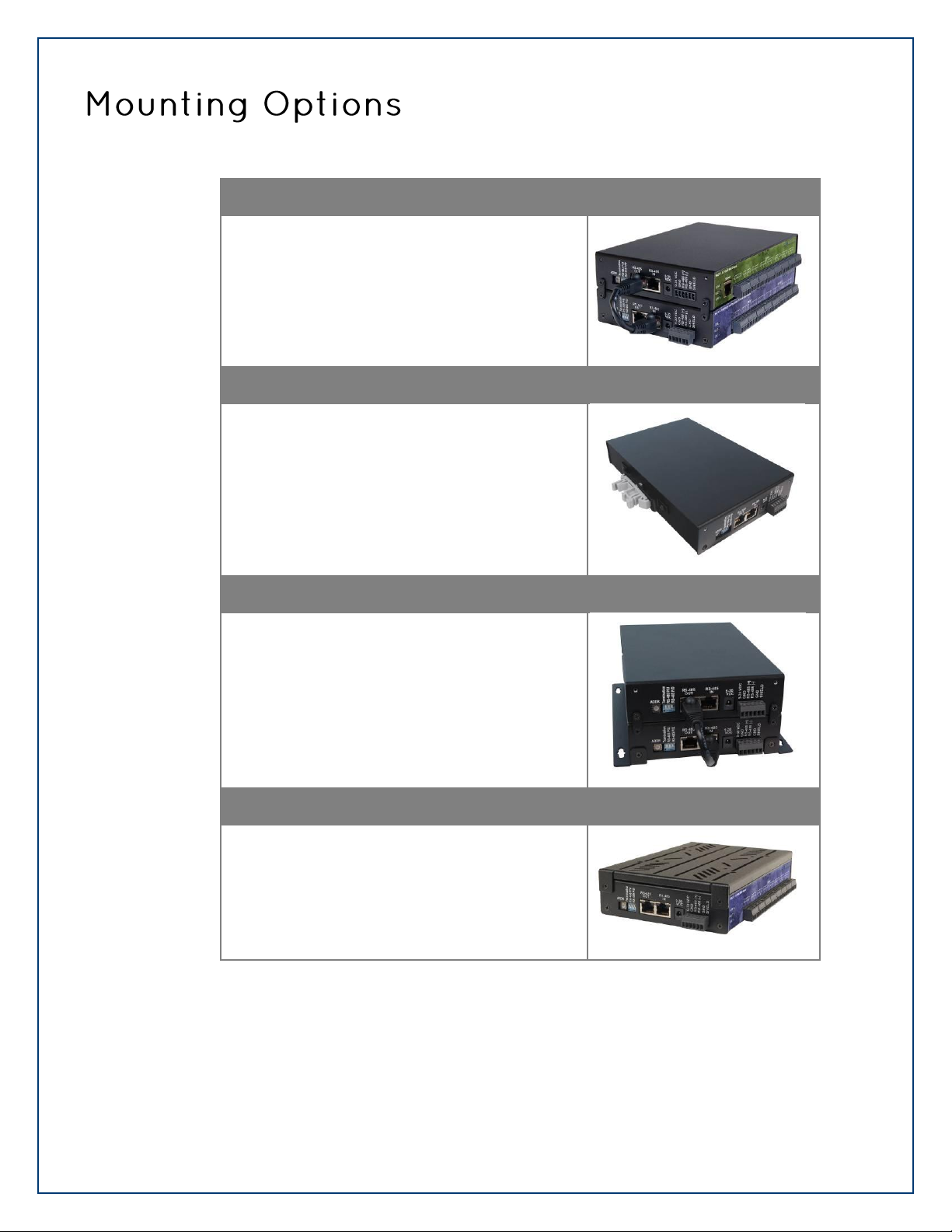
©Sealevel Systems, Inc.
SL9049 - 11/2010
SeaI/O Manual
98
SeaI/O Mounting Kit (Part# KT122)
Expanding your I/O count is as simple as adding NSeries expansion units to the Base SeaI/O module
(or other N-series modules). Each N-Series module
includes an expansion and strap kit (Part# KT122),
which includes a 5” CAT5 interconnect cable, four
metal straps, and four #4-40 metal screws. The
image shows a SeaI/O stack configuration using
the expansion kit.
DIN Rail Mounting (Part# DR104)
All SeaI/O modules are available with a factoryinstalled DIN-rail mounting clip. Alternatively DINrail mounting clips can be ordered as a field
upgrade kit (Part# DR104). The bracket with clip is
easily attached using two included #4-40 Phillips
head machine screws.
Table/Wall Mounting (Part# KT123)
The flush mount bracket kit (Part# KT123) is
extremely versatile and can be used to mount
SeaI/O modules from the top, bottom, or back
edge. Individual modules or a stack of SeaI/O
modules can be mounted flat to a tabletop,
underneath a counter, or inside an enclosure. The
kit can be used to mount SeaI/O modules flat to a
wall, or along the back edge, similar to DIN-rail
mounting options.
Universal Mounting Bracket (Part# KT125)
The universal mounting bracket (Part# KT125) can
be used as a “backpack” to mount power supplies
and other devices to SeaI/O modules. The bracket
has holes for both 75mm and 100mm VESA
mounting options. The universal arrangement of
slots and holes accept bolt sizes to M4 and can be
used for virtually any mounting configuration.
Page 99
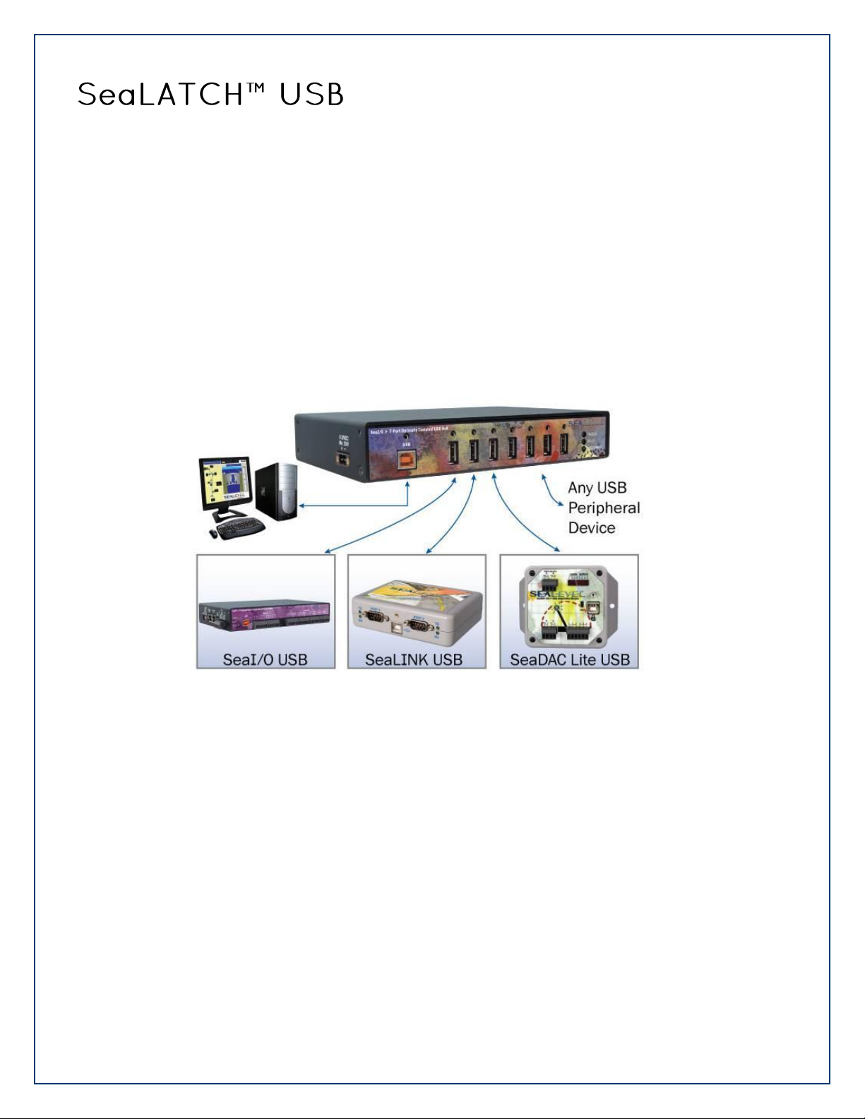
©Sealevel Systems, Inc.
SL9049 - 11/2010
SeaI/O Manual
99
SeaI/O USB modules integrate a patent-pending SeaLATCH USB port, which is fully compatible with
standard USB cables. When used with the included USB cable (Part# CA356) with a SeaLATCH USB
type B connector, the metal thumbscrew provides a secure metal-to-metal connection to the module
and prevents accidental cable disconnection.
Sealevel incorporates SeaLATCH locking USB ports on many USB hubs and I/O devices. Accidental
cable disconnection is the most common point of failure with USB industrial I/O devices and
SeaLATCH cables and connectors prevents that while being fully compatible with standard USB
cables.
Examples of the isolated 7-port USB hub (Part# SeaI/O-270U) with SeaLATCH equipped Sealevel I/O
devices are shown below.
Page 100
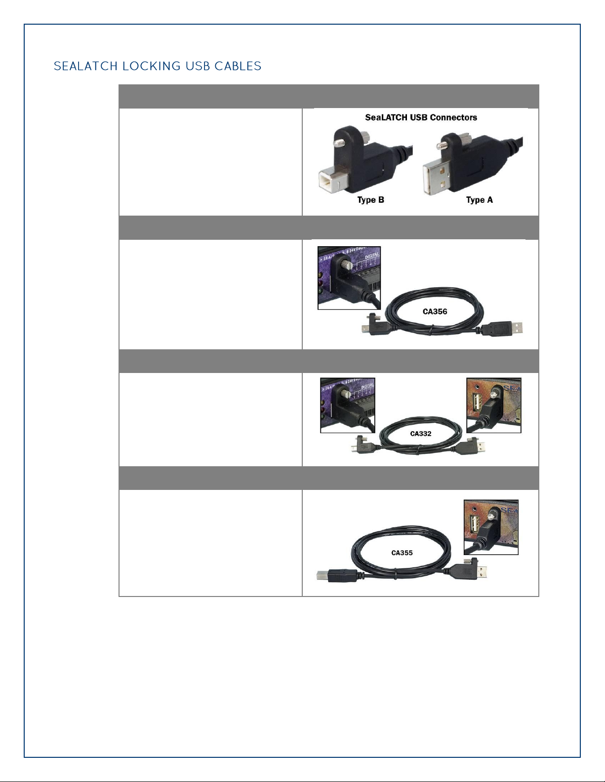
©Sealevel Systems, Inc.
SL9049 - 11/2010
SeaI/O Manual
100
SeaLATCH USB Connectors
SeaLATCH locking USB cables integrate
a small thumbscrew into each USB
connector. SeaLATCH USB cables are
fully interchangeable with standard USB
cables. The thumbscrew provides a
secure metal-to-metal connection
preventing accidental disconnection.
SeaLATCH USB cables are available in
three configurations.
72" USB cable with SeaLATCH type B and standard type A connectors (Part# CA356)
The CA356 is a 72” USB cable with a
SeaLATCH type B connector and a
standard USB type A connector. This
cable provides a secure connection
between Sealevel products with a
SeaLATCH type B port and legacy USB
type A ports. The CA356 is included
with Sealevel devices with a SeaLATCH
type B port.
72" USB cable with both SeaLATCH type A and type B USB connectors (Part# CA332)
The CA332 is a 72” cable with both
SeaLATCH type A and B connectors.
This cable secures both ends of the
cable to devices with SeaLATCH USB
ports and offers complete protection
against accidental cable disconnection.
72" USB cable with standard type B and SeaLATCH type A connectors (Part# CA355)
The CA355 is a 72” cable with a
standard USB type B and a SeaLATCH
type A connector. This cable provides a
secure connection between legacy USB
devices and Sealevel products with a
SeaLATCH type A port, such as the
isolated USB hub (Part# 270U).
 Loading...