

Page 1

SeaI/O User Manual
www.sealevel.com PO Box 830 – Liberty, SC 29657 864.843.4343
Page 2

Table of Contents
INTRODUCTION......................................................................................................................... 1
SEAI/O HARDWARE DESCRIPTION..................................................................................... 3
SEAI/O BASE AND EXPANSION MODULES ................................................................................... 3
SEAI/O MODULE COMMON FEATURES ........................................................................................ 4
SEAI/O CONFIGURATIONS & SPECIFICATIONS............................................................................. 5
410 Series – 16 Optically Isolated Inputs/16 Reed Relay Outputs......................................... 5
420 Series – 16 Optically Isolated Inputs/8 Form C Outputs................................................. 6
430 Series – 32 Optically Isolated Inputs............................................................................... 7
440 Series – 32 Reed Relay Outputs....................................................................................... 7
450 Series – 16 Form C Relay Outputs .................................................................................. 8
462 Series – 96 Channel TTL DB-78......................................................................................9
463 Series – 96 Channel TTL 50-Pin.................................................................................... 11
470 Series – 16 A/D, 2 D/A, 8 24V Outputs, 8 Isolated Inputs.............................................14
520 Series – 8 Optically Isolated Inputs/8 High-Current Form C Outputs.......................... 15
POWER OPTIONS .................................................................................................................... 16
BASE MODULE POWER CONNECTION......................................................................................... 16
SEAI/O EXPANSION POWER CONNECTION ................................................................................. 16
SeaI/O Max Power Requirements.........................................................................................16
TTL Power Requirements ..................................................................................................... 16
Sample Power Calculation ................................................................................................... 17
HARDWARE CONFIGURATION .......................................................................................... 18
SeaI/O-463 Ribbon Cable Installation Instructions ............................................................. 18
SeaI/O-470 Jumper and Dipswitch Settings Instructions..................................................... 21
SeaI/O-470 Jumper Locations .............................................................................................. 22
WIRING OPTIONS ................................................................................................................... 24
EAI/O PASS-THROUGH CONNECTOR........................................................................................24
S
I/O WIRING – SEAI/O-410, 420, 430, 440, AND 450 MODULES ................................................25
I/O WIRING – SEAI/O-462 AND 463 MODULES......................................................................... 26
I/O W
I/O W
IRING – SEAI/O-470 MODULES........................................................................................ 29
IRING – SEAI/O-520 MODULES........................................................................................ 32
CONNECTOR PIN OUTS............................................................................................................... 33
MOUNTING OPTIONS............................................................................................................. 34
ACCESSORIES .......................................................................................................................... 35
SEAMAX APPLICATION SUITE........................................................................................... 37
S
EAI/O ARCHITECTURE............................................................................................................. 38
EVICE ADDRESS CONFIGURATION ........................................................................................... 39
D
Setting Device Address (Slave ID)........................................................................................39
Setting Termination & Pull-Up/Pull-Down Resistors .......................................................... 40
CONFIGURING THE “BASE” SEAI/O MODULE ............................................................................ 41
© Sealevel Systems, Inc.
SL9049 Revision 8/2006
SeaI/O User Manual
Page 3

CONFIGURING N-SERIES EXPANSION MODULES........................................................................ 42
CONFIGURING AN ETHERNET MODULE (E-SERIES).................................................................... 43
MAXSSD CONFIGURATION & DIAGNOSTICS UTILITY............................................................... 46
Host PC Configuration Tab.................................................................................................. 46
SeaI/O Configuration Tab..................................................................................................... 47
Digital I/O Tab...................................................................................................................... 49
Programmable I/O Tab......................................................................................................... 50
A/D Inputs Tab...................................................................................................................... 51
D/A Outputs Tab................................................................................................................... 52
Diagnostics ........................................................................................................................... 53
COMMUNICATING VIA MODBUS ................................................................................................ 54
Modbus Commands............................................................................................................... 54
Modbus RTU......................................................................................................................... 55
Modbus TCP ......................................................................................................................... 55
EXTENDED MODBUS COMMAND SET......................................................................................... 56
DEVELOPING CUSTOM APPLICATIONS USING SEAMAX API .................................................... 64
SEAMAX API ........................................................................................................................... 65
NON OBJECT-ORIENTED SEAMAX API .................................................................................... 70
IOCTL CALLS AND FUNCTIONALITY......................................................................................... 73
USING SEAMAX WITH VISUAL C++ 6.0 ................................................................................... 79
USING SEAMAX WITH VISUAL BASIC 6.0................................................................................. 81
EXAMPLE SEAMAX PROGRAMMING TASKS.............................................................................. 82
CETHERNET API...................................................................................................................... 87
APPENDIX A – DATA ENCODING TABLES....................................................................... 95
APPENDIX B – CRC CALCULATION................................................................................... 96
APPENDIX C – SEAIO MODEL 462/463 HOLDING REGISTER SET............................. 97
APPENDIX D – SEAMAX DATA TYPES AND STRUCTURES......................................... 98
APPENDIX E – TROUBLESHOOTING............................................................................... 102
APPENDIX F – HOW TO GET ASSISTANCE.................................................................... 104
APPENDIX G – COMPLIANCE NOTICES......................................................................... 105
WARRANTY............................................................................................................................. 106
© Sealevel Systems, Inc.
SL9049 Revision 8/2006
SeaI/O User Manual
Page 4

Introduction
SeaI/O
TM
modules provide a powerful way to add I/O to a variety of computers,
controllers, and PLCs. Each SeaI/O model is designed for maximum flexibility and
easy field wiring. Ordering options allow connection to the host device via Wireless
802.11b/g (Coming Soon!), Ethernet, USB, RS-485, or RS-232, and multiple units
can be daisy chained together using convenient pass-through connectors. For easy
software integration, application programs or 3
SeaMAX
TM
library or industry standard Modbus protocol.
rd
party software can use the Sealevel
This manual covers the installation and operation of these SeaI/O products:
Ethernet 10/100 BaseT
SeaI/O-410E – 16 Optically Isolated Inputs/16 Reed Relay Outputs
SeaI/O-420E – 16 Optically Isolated Inputs/8 Form C Outputs
SeaI/O-430E – 32 Optically Isolated Inputs
SeaI/O-440E – 32 Reed Relay Outputs
SeaI/O-450E – 16 Form C Relay Outputs
SeaI/O-462E – 96 Bit TTL I/O (DB-78)
SeaI/O-463E – 96 Bit TTL I/O (50-Pin IDC)
SeaI/O-470E – 8 Inputs/8 Outputs/2 D/A & 16 A/D
SeaI/O-520E – 8 Optically Isolated Inputs/8 High-Current Form C Outputs
USB
SeaI/O-410U – 16 Optically Isolated Inputs/16 Reed Relay Outputs
SeaI/O-420U – 16 Optically Isolated Inputs/8 Form C Outputs
SeaI/O-430U – 32 Optically Isolated Inputs
SeaI/O-440U – 32 Reed Relay Outputs
SeaI/O-450U – 16 Form C Relay Outputs
SeaI/O-462U – 96 Bit TTL I/O (DB-78)
SeaI/O-463U – 96 Bit TTL I/O (50-Pin IDC)
SeaI/O-470U – 8 Inputs/8 Outputs/2 D/A & 16 A/D
SeaI/O-520U – 8 Optically Isolated Inputs/8 High-Current Form C Outputs
RS-485
SeaI/O-410M – 16 Optically Isolated Inputs/16 Reed Relay Outputs
SeaI/O-420M – 16 Optically Isolated Inputs/8 Form C Outputs
SeaI/O-430M – 32 Optically Isolated Inputs
SeaI/O-440M – 32 Reed Relay Outputs
SeaI/O-450M – 16 Form C Relay Outputs
SeaI/O-462M – 96 Bit TTL I/O (DB-78)
SeaI/O-463M – 96 Bit TTL I/O (50-Pin IDC)
SeaI/O-470M – 8 Inputs/8 Outputs/2 D/A & 16 A/D
SeaI/O-520M – 8 Optically Isolated Inputs/8 High-Current Form C Outputs
RS-232
SeaI/O-410S – 16 Optically Isolated Inputs/16 Reed Relay Outputs
SeaI/O-420S – 16 Optically Isolated Inputs/8 Form C Outputs
SeaI/O-430S – 32 Optically Isolated Inputs
SeaI/O-440S – 32 Reed Relay Outputs
SeaI/O-450S – 16 Form C Relay Outputs
SeaI/O-462S – 96 Bit TTL I/O (DB-78)
SeaI/O-463S – 96 Bit TTL I/O (50-Pin IDC)
SeaI/O-470S – 8 Inputs/8 Outputs/2 D/A & 16 A/D
SeaI/O-520S – 8 Optically Isolated Inputs/8 High-Current Form C Outputs
Expansion Units (Connect to Base Unit via RS-485)
SeaI/O-410N – 16 Optically Isolated Inputs/16 Reed Relay Outputs
SeaI/O-420N – 16 Optically Isolated Inputs/8 Form C Outputs
SeaI/O-430N – 32 Optically Isolated Inputs
SeaI/O-440N – 32 Reed Relay Outputs
SeaI/O-450N – 16 Form C Relay Outputs
SeaI/O-462N – 96 Bit TTL I/O (DB-78)
SeaI/O-463N – 96 Bit TTL I/O (50-Pin IDC)
SeaI/O-470N – 8 Inputs/8 Outputs/2 D/A & 16 A/D
SeaI/O-520N – 8 Optically Isolated Inputs/8 High-Current Form C Outputs
© Sealevel Systems, Inc.
- 1 -
SeaI/O User Manual
Page 5

Software Installation
SeaI/O modules can be used with industry standard Modbus protocol or easily
controlled from application programs using the supplied SeaMAX software libraries.
Included are two diagnostic and configuration tools: MaxSSD and Ethernet Config.
The SeaMAX library features an object-oriented and functional interface for use with
C++ and Visual Basic. Also included is the CEthernet API library for programmatic
discovery and configuration of Ethernet enabled SeaI/O modules. Refer to the
SeaMAX Application Suite section of this manual for detailed information.
Industry Segments
SeaI/O modules are perfect for a wide variety of applications and environments
including:
Process Control
Data Acquisition
Broadcast Automation
Security
Facility Management
Features
Choice of Connectivity:
o Wireless (802.11b/g) – coming soon!
o Ethernet
o USB
o RS-485
o RS-232
Supports Industry Standard Modbus TCP & RTU Protocols
Models Offering Choice of:
o Optically Isolated Inputs
o Reed Relay Outputs
o Form C Relay Outputs
o TTL Interfaces
o Analog A/D & D/A
Status Indicator LEDs for Communication, Fault, and Status
Field Removable Terminal Block Connectors (most models)
9-30VDC Power Input
Power Input via Terminal Block or DC Jack
Daisy Chain up to 247 Modules
Extended Temperature Available (-40°C to +85°C)
Rugged Metal Enclosure
Compact Size - 7.5"(L) x 5.1"(W) x 1.3"(H)
Din Rail or Table Mount
© Sealevel Systems, Inc.
- 2 -
SeaI/O User Manual
Page 6

SeaI/O Hardware Description
SeaI/O Base and Expansion Modules
Base Modules connect to the host via one of the following interfaces:
E-Series - Ethernet Modbus TCP
U-Series - USB Modbus RTU
M-Series - RS-485 Modbus RTU
S-Series - RS-232 Modbus RTU
After the Base unit is installed, up to 246 additional SeaI/O N-Series Expansion
Units can be added to create an I/O network. These expansion modules interface via
RS-485 and can be located local to the Base SeaI/O device or remotely located up to
4000 feet away. Local installations should use the 5” CAT5 RS-485 pass-through
cable (Item number CA239) shipped with each N-series module to connect. Remote
expansion modules should use RS-485 twisted pair wiring from the Base unit
connected via the removable screw terminal connector.
For local installations power to the expansion modules is supplied from the Base unit
via the pass-through connectors. For remote devices, separate power is required at
each expansion unit. Refer to the Power Options section of this manual for more
information on SeaI/O power requirements and power supply sizing.
Included Communications and Expansion Accessories
SeaI/O modules are shipped with the following accessories:
E-Series (Ethernet) Item# CA246 – 1 x 7’ straight through Ethernet cable, for
connection to a hub or switch.
Item# CA251 – 1 x 7’ crossover cable, for direct connection to a
computer’s Ethernet port.
U-Series (USB) Item# CA179 – 6’ A to B USB cable.
M-Series (RS-485)
S-Series (RS-232) Item# KT119 – RS-232 DB9/RJ45 Kit, includes a DB9F to RJ45
N-Series (Expansion) KT122 – Expansion & Strap Kit, includes 5” CAT5 RS-485
All Models
No cable is included. RS-485 twisted-pair wiring connects to screw
terminals.
adapter with RS-232 pinout (Item# DB109) and a 7’ CAT5 patch
cable (Item# CA246) for connecting SeaI/O modules to both
Sealevel and standard RS-232 serial ports.
interconnect cable, four metal straps, and four #4-40 metal screws,
for connecting two or more SeaI/O modules together in a “stack”.
Each SeaI/O unit is shipped with 4 adhesive rubber feet that can be
attached to the bottom of the enclosure to enhance stability in table
mount applications.
© Sealevel Systems, Inc.
- 3 -
SeaI/O User Manual
Page 7

SeaI/O Module Common Features
All SeaI/O modules include the same connectors and configuration options on the
side of the unit:
NOTE:
RS-485 networks should have termination enabled on each end of
the network. Pull-up and pull-down resistors should also be enabled
on the last device on the network.
The 9-30VDC input barrel connector is center positive.
Status LEDs are included on the front of all SeaI/O devices to indicate
Communication (Yellow), Fault (Red), and Status (Green).
© Sealevel Systems, Inc.
- 4 -
SeaI/O User Manual
Page 8

SeaI/O Configurations & Specifications
410 Series – 16 Optically Isolated Inputs/16 Reed Relay Outputs
SeaI/O-410 modules provide 16 optically isolated inputs and 16 Reed relay outputs.
Inputs can range from 5-24VDC, while the Reed relays provide long life switch
closures that are well suited for low current applications. Inputs and outputs are
grouped into four-bit segments. Each group shares a common for easy wiring via
removable 3.5mm terminal blocks.
Inputs
Type: 16 non-polarized optically isolated inputs
Voltage Range: 5-24VDC
Isolation: 300V
Input Resistance: 6.2K Ohms in series
Response Time: 4 microseconds
Outputs
Type: 16 SPST Form A Reed relays
Power: 10VA max.
Contact Voltage: 60VDC max.
Contact Current: 500mA max.
Operate Time: 0.5ms max.
Bounce Time: 0.5ms max.
Release Time: 0.2ms max.
© Sealevel Systems, Inc.
- 5 -
SeaI/O User Manual
Page 9

420 Series – 16 Optically Isolated Inputs/8 Form C Outputs
The SeaI/O-420 provides 16 optically isolated inputs and 8 SPDT Form C relay
outputs. Inputs can range from 5-24VDC and provide 300V isolation to ground. Each
output offers normally open and normally closed contact connections via 3.5mm field
removable terminal blocks.
Inputs
Type: 16 non-polarized optically isolated inputs
Voltage Range: 5-24VDC
Isolation: 300V
Input Resistance: 6.2K Ohms in series
Response Time: 4 microseconds
Outputs
Type: 8 SPDT Form C relays
Power: DC 30W/ AC 60 VA
Contact Voltage: 60VDC max.
Contact Current: 2A max.
Operate Time: 2ms max.
Bounce Time: 7ms max.
Release Time: 1ms max.
© Sealevel Systems, Inc.
- 6 -
SeaI/O User Manual
Page 10

430 Series – 32 Optically Isolated Inputs
SeaI/O-430 modules provide 32 optically isolated inputs with 300V external isolation
and high channel-to-channel isolation. Ideal for low voltage monitoring applications,
connection to real world signals is made via 3.5mm convenient removable screw
terminal connectors.
Inputs
Type: 32 non-polarized optically isolated inputs
Voltage Range: 5-24VDC
Isolation: 300V
Input Resistance: 6.2K Ohms in series
Response Time: 4 microseconds
440 Series – 32 Reed Relay Outputs
The SeaI/O-440 provides 32 SPST Form A dry contact Reed relays. Reed relays offer
long life performance and fast response time. Convenient removable 3.5mm screw
terminal blocks compatible with 14-22 AWG wiring allow reliable connection to real
world I/O.
Outputs
Type: 32 SPST Form A Reed relays
Power: 10VA max.
Contact Voltage: 60VDC max.
Contact Current: 500mA max.
Operate Time: 0.5ms max.
Bounce Time: 0.5ms max.
Release Time: 0.2ms max.
© Sealevel Systems, Inc.
- 7 -
SeaI/O User Manual
Page 11

450 Series – 16 Form C Relay Outputs
Control a variety of low voltage, low current devices with the SeaI/O-450. The
module’s 16 channels of highly reliable SPDT Form C relay outputs are rated for up
to 60VDC @ 2A. Each output offers normally open and normally closed contact
connections via 3.5mm field removable terminal blocks.
Outputs
Type: 16 SPDT Form C relays
Power: DC 30W/ AC 60 VA
Contact Voltage: 60VDC max.
Contact Current: 2A max.
Operate Time: 2ms max.
Bounce Time: 7ms max.
Release Time: 1ms max.
© Sealevel Systems, Inc.
- 8 -
SeaI/O User Manual
Page 12

462 Series – 96 Channel TTL DB-78
Perfect for driving industry-standard solid-state relay (SSR) racks, the SeaI/O-462
provides 96 bits of buffered drive TTL I/O. Each DB-78 connector brings out 48 I/O
bits addressable as six, eight-bit ports. For easy connection to relay racks, Sealevel
offers a six-foot cable (Item# CA237) that terminates each DB-78 connector to two
industry standard 50-pin IDC connectors. Order part number 462x-KT and receive
two CA237 cables with each unit.
Power Requirements
Max Output Power: +5VDC @ 1A (5W)
Inputs
Logic High: Min 2VDC
Logic Low: Max 0.8VDC
Outputs
Logic High: Min 2VDC @ 32mA
Logic Low: Max 0.5VDC @ 64mA
© Sealevel Systems, Inc.
- 9 -
SeaI/O User Manual
Page 13

SeaI/O-462 Optional Items
Depending upon your application, you are likely to find one or more of the following
items useful for interfacing the SeaI/O-462 to real-world signals. All items can be
purchased from our website (http://www.sealevel.com
For high-current, high-voltage applications:
DB-78 to Dual IDC 50 Pin Ribbon Cable (Item Number CA237)
− 60” cable connects each SeaI/O-462’s DB-78 connectors to solid-state
relay racks equipped with 50-pin header interface.
Solid-State Relay Racks:
• Quad six position relay rack (Part Number PB24HQ)
− Relay rack can accept up to six QSSRs for a total of 24 channels.
Features a 50-pin header connector for easy interface via 50conductor ribbon cables.
• Quad four position relay rack (Part Number PB16HQ)
− Relay rack can accept up to four QSSRs for a total of 16 channels.
Features a 50-pin header connector for easy interface via 50conductor ribbon cables.
Quad Solid-State Relay Modules:
• AC Input (Part Number IA5Q) – Provides 4 channels of discrete I/O
interface to monitor AC inputs up to 140V @ 10mA.
• DC Input (Part Number IB5Q) – Provides 4 channels of discrete I/O
interface to monitor DC inputs from 3.3V to 32V.
• AC Output (Part Number OA5Q) – Provides 4 channels of discrete I/O
interface to control AC outputs up to 140V @ 3A.
• DC Output (Part Number OB5Q) – Provides 4 channels of discrete I/O
interface to control DC outputs up to 60V @ 3A.
Simulation/debug module (Part Number TA01)
− Module simulates the operation and load characteristics of a standard 24-
channel relay rack. An LED corresponding to each port bit illuminates to
indicate state. Eight position DIP-switches are used to generate input status
changes.
) or by calling 864-843-4343.
© Sealevel Systems, Inc.
- 10 -
SeaI/O User Manual
Page 14

463 Series – 96 Channel TTL 50-Pin
The SeaI/O-463 offers 96 bits of buffered drive TTL I/O via four internal industrystandard 50-pin header connectors. The interface module addresses the 96 channels
of I/O as 12 eight-bit ports, each programmable as input or output. Using standard
50-pin IDC ribbon cables, connect up to four industry standard relay racks for PC
based control and automation of equipment including sensors, switches, security
control systems, and other industrial automation systems. A metal strain relief
bracket is included to secure the cables after installation.
Power Requirements
Max Output Power: +5VDC @ 1A (5W)
Inputs
Logic High: Min 2VDC
Logic Low: Max 0.8VDC
Outputs
Logic High: Min 2VDC @ 32mA
Logic Low: Max 0.5VDC @ 64mA
© Sealevel Systems, Inc.
- 11 -
SeaI/O User Manual
Page 15

SeaI/O-463 Optional Items
Depending upon your application, you are likely to find one or more of the following
items useful for interfacing the SeaI/O-463 to real-world signals. All items can be
purchased from our website (http://www.sealevel.com
For TTL applications:
Terminal Block Kit - (Item# KT107)
− Kit includes the TB07 screw terminal block and CA167 ribbon cable for
connecting one of the SeaI/O-463’s 50-pin header connectors to your I/O.
6” Snap track and DIN rail clips are included for DIN rail mounting.
IDC 50 to IDC 50 Pin 40" Ribbon Cable (Item# CA167)
− Interfaces each of the SeaI/O-463’s 50-pin header connectors.
Simulation/debug module (Item# TA01)
− Module allows monitoring status of output pins and controlling state of
input pins. An LED corresponding to each port bit illuminates to indicate
state. Eight position DIP-switches are used to generate input status
changes.
) or by calling 864-843-4343.
© Sealevel Systems, Inc.
- 12 -
SeaI/O User Manual
Page 16

For high-current, high-voltage applications:
IDC 50 to IDC 50 Pin Ribbon Cable (Item# CA167)
− 40” cable connects the SeaI/O-463 to solid-state relay racks equipped with
50-pin header interface.
IDC 50 to IDC 50 Pin Ribbon Cable (Item# CA135)
− 40” cable connects the SeaI/O-463 to solid-state relay racks equipped with
50-pin edge connector.
Solid-State Relay Racks:
• Quad six position relay rack (Item# PB24HQ)
− Relay rack can accept up to six QSSRs for a total of 24 channels.
Features a 50-pin header connector for easy interface via 50conductor ribbon cables.
• Quad four position relay rack (Item# PB16HQ)
− Relay rack can accept up to four QSSRs for a total of 16 channels.
Features a 50-pin header connector for easy interface via 50conductor ribbon cables.
Quad Solid-State Relay Modules:
• AC Input (Item# IA5Q) – Provides 4 channels of discrete I/O interface to
monitor AC inputs up to 140V @ 10mA.
• DC Input (Item# IB5Q) – Provides 4 channels of discrete I/O interface to
monitor DC inputs from 3.3V to 32V.
• AC Output (Item# OA5Q) – Provides 4 channels of discrete I/O interface to
control AC outputs up to 140V @ 3A.
• DC Output (Item# OB5Q) – Provides 4 channels of discrete I/O interface to
control DC outputs up to 60V @ 3A.
Simulation/debug module (Item# TA01)
− Module simulates the operation and load characteristics of a standard 24-
channel relay rack. An LED corresponding to each port bit illuminates to
indicate state. Eight position DIP-switches are used to generate input status
changes.
© Sealevel Systems, Inc.
- 13 -
SeaI/O User Manual
Page 17

470 Series – 16 A/D, 2 D/A, 8 24V Outputs, 8 Isolated Inputs
Designed using the Maxim MAX197 successive approximation-type A/D chip, the
SeaI/O-470 provides eight differential or 16 single-ended 12-bit inputs. The A/D
inputs can be individually configured for sensing 4-20mA current loop signals.
Additionally, the module provides two 12-bit D/A output channels, eight optically
isolated inputs, and eight open collector outputs, ideal for driving 24V devices
commonly found in industrial environments. Perfect for a variety of data
acquisition/control and test & measurement applications, the SeaI/O-470 includes
removable screw terminals, which simplify field-wiring connections.
Optically Isolated Inputs
Input Range: 5-30VDC
Open Collector Outputs
Output Voltage: Max. 30VDC
Output Current: Max. 500mA (single output)
Output Current: Max. 580mA (all outputs)
A/D Inputs
Number of Channels: 8 differential or 16 single-ended
Resolution: 12-bits
Sampling Rate: 100K/s
A/D Input Range
Software Selectable: 0-5V, 0-10V, +/-5V, +/-10V
Hardware Selectable: 0-20mA current loop (for 4-20mA devices)
D/A Outputs
Number of Channels: 2 single-ended
Resolution: 12-bits
Output Range: 0-5V, 0-10V
Load Resistance: Min. 2K
© Sealevel Systems, Inc.
- 14 -
SeaI/O User Manual
Page 18

520 Series – 8 Optically Isolated Inputs/8 High-Current Form C Outputs
The SeaI/O-520 provides 8 optically isolated inputs and 8 SPDT high-current Form C
relay outputs. Inputs can range from 5-30VDC and provide 300V isolation to ground.
Each output offers normally open and normally closed contact connections via
3.5mm field removable terminal blocks.
Inputs
Type: 8 non-polarized optically isolated inputs
Voltage Range: 5-30VDC
Isolation: 300V
Input Resistance: 6.2K Ohms in series
Response Time: 4 microseconds
Outputs
Type: 8 SPDT High-Current Form C relays
Contact Voltage: 250VAC/100VDC max.
Contact Current: 6A max.
Operate Time: 10ms max.
Release Time: 10ms max.
© Sealevel Systems, Inc.
- 15 -
SeaI/O User Manual
Page 19

Power Options
Base Module Power Connection
Base modules are powered from a 9-30VDC source using either the DC jack or screw
terminals on the side of the unit. Sealevel offers several power supply choices to
make connection easy (see Accessories chapter at the end of this document).
SeaI/O Expansion Power Connection
Each SeaI/O product, including the expansion modules, contains an onboard
switching regulator power supply rated for 9-30VDC. For local installations (less
than 10’ apart), expansion unit power is usually supplied from the Base unit via the
pass-through connectors. The number of expansion modules that can be driven from
the Base unit depends on the power source and number/type of expansion units.
Refer to the chart below for power requirements. For expansion modules mounted
remotely (greater than 10’ apart), separate power is required at each expansion unit.
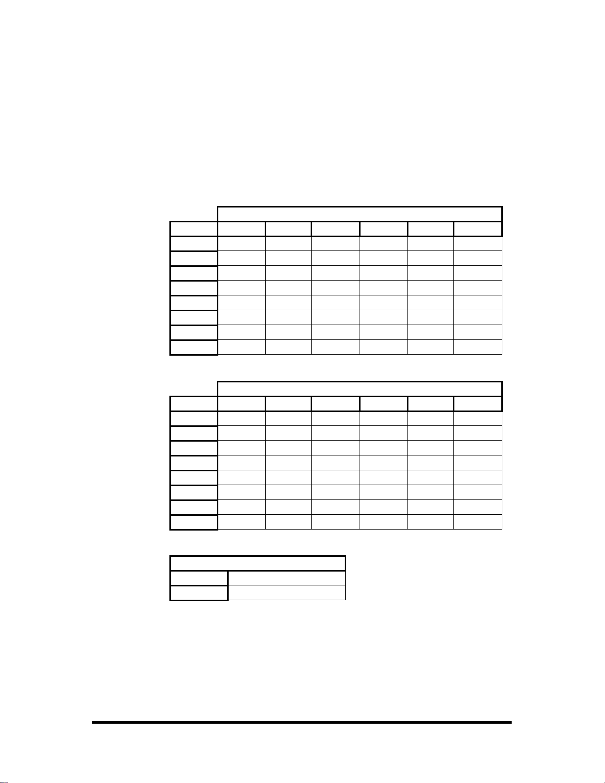
SeaI/O Max Power Requirements
SeaI/O-410 2.9W 1.7W 1.4W 1.6W 1.4W
SeaI/O-420 3.5W 2.3W 2.0W 2.2W 2.0W
SeaI/O-430 1.9W 0.7W 0.4W 0.6W 0.4W
SeaI/O-440 4.0W 2.8W 2.5W 2.7W 2.5W
SeaI/O-450 5.3W 4.1W 3.8W 4.0W 3.8W
SeaI/O-470 3.0W 1.8W 1.5W 1.7W 1.5W
SeaI/O-520 5.0W 3.8W 3.5W 3.7W 3.5W
TTL Power Requirements
The SeaI/O-462 and SeaI/O-463 use 74ABT245 octal bi-directional transceivers to
provide TTL input/output capabilities and can sink 64mA and source 32mA. Each
bit is pulled to +5V through a 10K ohm pull-up resistor to insure each bit is at a
known state when not driven. The supply current and maximum output power are
shown below.
SeaI/O-462 2.0W 0.8W 0.5W 0.7W 0.5W
SeaI/O-463 2.0W 0.8W 0.5W 0.7W 0.5W
Output Power +5VDC @ 1A (5W) Maximum
E-Series U-Series M-Series S-Series N-Series
E-Series U-Series M-Series S-Series N-Series
© Sealevel Systems, Inc.
- 16 -
SeaI/O User Manual
Page 20
Sample Power Calculation
A typical application for SeaI/O products would use one Base module and several Nseries units in a local expansion configuration. In this arrangement, with power
applied to the Base module through either the DC jack or screw terminal connector
and passed-through to the expansion units, attention should be given to ensure the
input power to the Base module is adequate.
Example:
Power (W)
Base Unit: SeaI/O-430U 0.7
Expansion 1: SeaI/O-410N 1.4
Expansion 2: SeaI/O-440N 2.5
4.6W Power Required
In this application, the Sealevel Item# TR112 “wall wart” power supply is a good
choice since it is low-cost and supplies 24VDC @ 250mA (6W).
NOTE:
A complete listing of recommended power supplies is provided in
the Accessories section of this manual.
© Sealevel Systems, Inc.
- 17 -
SeaI/O User Manual
Page 21
Hardware Configuration
The SeaI/O-463 and SeaI/O-470 are the only two modules that require you to open
the enclosure. On all SeaI/O modules, most device settings can be configured on the
left side of the SeaI/O module. Refer to the SeaI/O Hardware Description section
of this manual for a list of common features available and settings that can be
changed on the left side of the SeaI/O module.
When connecting more than one SeaI/O module to a host computer, you will need to
set the device address (Slave ID). This can be done in software or by using a rotary
switch on the left side of the enclosure. Refer to the SeaMAX Application Suite
section where you can find instructions for configuring the device address (Slave ID)
and setting the termination pull up and pull down resistors.
SeaI/O-463 Ribbon Cable Installation Instructions
A copy of these instructions are included with the SeaI/O-463 module and can also
be downloaded from the SeaI/O-463 product page on the Sealevel website.
NOTE:
Do not perform these instructions with the power connected. Be
sure to follow proper ESD procedures by grounding yourself and the
SeaI/O module.
What you will need:
SeaI/O-463 module
Phillips head screwdriver
Slotted screwdriver
50-pin IDC ribbon cable* (up to four)
*Ribbon cable accessories available:
• CA167 – 40” IDC 50-pin to IDC 50-pin ribbon cable
• CA197 – 18” IDC 50-pin to IDC 50-pin ribbon cable
• CA135 – 40” IDC 50-pin to 50-pin edge connector ribbon cable
Step 1
Remove the terminal block from the left side and
then remove the two black screws from each side
of the module as shown in the image.
© Sealevel Systems, Inc.
- 18 -
SeaI/O User Manual
Page 22

Step 2
On the front right side of the module, wedge a
slotted screwdriver between the top and bottom
halves as shown. Pry upwards – a pem in the top
half must clear the metal lip in the bottom half of
the enclosure.
Step 3
Remove the two screws from the metal strain
relief, as shown.
Step 4
Remove the three screws from the bottom of the
module and remove the front plate.
Step 5
Install up to four industry standard ribbon cables
in the 50-pin header connectors. A list of optional
cable part numbers is listed on the previous page.
Step 6
Replace the front plate and install the three screws
in the bottom of the module as shown.
© Sealevel Systems, Inc.
- 19 -
SeaI/O User Manual
Page 23

Step 7
Replace the metal strain relief. Start both screws
and tighten only until snug. Do not over-tighten.
Step 8
Replace the top half by starting it on the left side
over the connectors and then snapping the right
side down into place. Be careful not to pinch
fingers. Replace both screws on each side and
then replace the terminal block on the left side.
Step 9
Continue with the installation of the SeaI/O-463
module. The SeaI/O Hardware Description
section of this manual contains information on
TTL applications and optional accessories. The
SeaMAX Application Suite section walks you
through setting up the hardware address (Slave ID)
and software installation.
© Sealevel Systems, Inc.
- 20 -
SeaI/O User Manual
Page 24

SeaI/O-470 Jumper and Dipswitch Settings Instructions
The SeaI/O-470 module ships factory configured with the D/A outputs set for 0-10V
and current loop mode on the A/D inputs disabled. If you need to enable current loop
mode or set the D/A outputs to 0-5V, you will need to open the enclosure and access
the jumpers (shown on the next page).
NOTE:
Do not perform these instructions with the power connected. Be
sure to follow proper ESD procedures by grounding yourself and the
SeaI/O module.
What you will need:
SeaI/O-470 module
Phillips head screwdriver
Slotted screwdriver
Step 1
Remove the terminal block from the left side and
then remove the two black screws from each side
of the module as shown in the image.
Step 2
On the front right side of the module, wedge a
slotted screwdriver between the top and bottom
halves as shown. Pry upwards – a pem in the top
half must clear the metal lip in the bottom half of
the enclosure.
Jumpers and dipswitch locations are shown on the
following page.
© Sealevel Systems, Inc.
- 21 -
SeaI/O User Manual
Page 25

SeaI/O-470 Jumper Locations
This detail image of the right side of the SeaI/O-470 circuit board shows the locations
of the user configurable jumpers and dipswitches. Refer to the following pages for
instructions on properly configuring the jumpers and switches. The colored boxes
are shown here for clarity and are not visible on the actual circuit board.
© Sealevel Systems, Inc.
- 22 -
SeaI/O User Manual
Page 26

D/A Settings
The (E1) and (E2) jumpers (shown in the orange boxes on the previous page)
configure the D/A outputs for 0-5V or 0-10V. Both channels can be configured
independently. The D/A outputs do not support negative voltages. You must also set
the correct output voltage in your application or MaxSSD. Refer to the SeaMAX
Application Suite section of this manual for help configuring software to work with
the SeaI/O-470.
A/D 10X Gain
The A/D 10X gain (E3) jumper (shown in the green box on the previous page) is
disabled at the factory. Position the hardware jumper on both pins to enable this
functionality, which allows smaller voltages to be measured more accurately (e.g., a
0-1V input signal can be measured more accurately by enabling the 10x hardware
gain jumper and setting the SeaI/O-470 A/D input channel for 0-10V range). You
can also set the A/D input channel for 0-5V to sense voltages smaller than 0.5V.
When the jumper is enabled, the “10X Hardware Gain” checkbox will also be
enabled on the A/D Inputs tab in MaxSSD. Refer to the SeaMAX Application Suite
section of this manual for information on using MaxSSD.
A/D and Current Loop Dipswitches
The (SW3) and (SW4) dipswitches (shown in the yellow box on the previous page)
configure the A/D inputs for current loop mode and are disabled at the factory. Since
current loop mode is differential, the corresponding dipswitch on both (SW3) and
(SW4) should be properly set (e.g., ‘CH1’ on both dipswitches needs to be set to
‘ON’ to enable current loop mode).
SW3 – enables the current-loop sensing resistor
SW4 – ties the other half of connection to ground
© Sealevel Systems, Inc.
- 23 -
SeaI/O User Manual
Page 27
Wiring Options
SeaI/O Pass-Through Connector
All SeaI/O modules include two RS-485 pass-through connectors on the left side of
the unit that are internally connected to the same pins on the screw terminals. This
offers two convenient options for adding additional expansion modules.
For connecting several SeaI/O modules together in a “stack”, all N-series expansion
modules ship with an expansion and strap kit (item# KT122) that includes four metal
straps, four #4-40 screws, and a 5” RJ45 RS-485 interconnect cable (item# CA239).
The metal straps allow you to securely connect multiple SeaI/O modules together.
The interconnect cable can be used to connect SeaI/O modules together via the RJ45
pass-through connectors, providing an easy method to cascade RS-485 signals and
power from one module to the next.
For expansion modules that are less than ten feet from a base unit, a standard RJ45
CAT5 patch cable may be used. For SeaI/O modules greater than ten feet apart, use
twisted-pair cable connecting the data lines to the screw terminals instead. If RJ45
connectors are preferred, be sure to connect only the data lines (pins 4 & 5).
NOTE:
Modules greater than ten feet apart must have separate power
supplies. Refer to the Power Options section of this manual for
recommendations.
© Sealevel Systems, Inc.
- 24 -
SeaI/O User Manual
Page 28
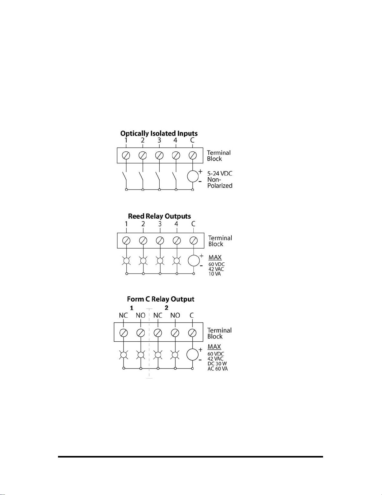
I/O Wiring – SeaI/O-410, 420, 430, 440, and 450 Modules
Optically isolated inputs are arranged such that each group of four shares a single
common. The four I/O points and shared common are connected via a five-position
removable screw terminal. Input voltage range is 5-24VDC. Like the inputs, each
group of four Reed relays also shares a single common and connects via a fiveposition removable screw terminal. Form C Relay outputs are arranged such that each
group of two relays shares a common. The NC and NO contacts of each relay along
with the common are brought out via a five-position removable screw terminal.
© Sealevel Systems, Inc.
- 25 -
SeaI/O User Manual
Page 29
I/O Wiring – SeaI/O-462 and 463 Modules
SeaI/O-462 DB-78F Connectors
The SeaI/O-462’s 96 digital I/O channels are brought out to two DB-78 Female
connectors on the front of the enclosure (pinout shown below). Each connector
provides 48 bits of digital I/O divided into six eight-bit ports. Each port may be
individually configured via software command as an input or an output.
Bits A1 B1 C1 A2 B2 C2
D0
D1
D2
D3
D4
D5
D6
D7
Bits A3 B3 C3 A4 B4 C4
D0
D1
D2
D3
D4
D5
D6
D7
+5V
Commons 41 – 58, 64 – 73
75 38 18 10 30 2
76 37 17 9 29 1
77 36 16 8 28 22
78 35 15 7 27 21
59 34 14 6 26 40
39 33 13 5 25 60
20 32 12 4 24 61
19 31 11 3 23 62
75 38 18 10 30 2
76 37 17 9 29 1
77 36 16 8 28 22
78 35 15 7 27 21
59 34 14 6 26 40
39 33 13 5 25 60
20 32 12 4 24 61
19 31 11 3 23 62
Power & Commons
63, 74
Bits 1-48
Bits 49-96
© Sealevel Systems, Inc.
- 26 -
SeaI/O User Manual
Page 30

SeaI/O-462 Optional Cable (Item# CA237) Pinout
For easy connection to industry-standard solid-state relay racks, Sealevel
manufactures a 6’ cable, Item# CA237, that terminates the DB-78 to two industry
standard 50-pin header connectors. Two cables and a SeaI/O unit can be order
together as a kit using Item# 462x-KT. The pinout for the two 50-pin headers is
shown below.
© Sealevel Systems, Inc.
- 27 -
SeaI/O User Manual
Page 31

SeaI/O-463 50-Pin Header Connectors
The SeaI/O-463’s 96 digital I/O channels are accessed via four industry-standard 50pin header connectors. Each header provides 24 bits of digital I/O divided into three
eight-bit ports. Each port may be individually configured via software command as
an input or an output.
You will need to open the SeaI/O-463’s enclosure to access the four header
connectors: P2, P3, P4, and P5. The connector designators are silk-screened onto the
PCB for easy identification. Once cables are connected to the headers, route them
through the opening in the front of the enclosure, attach the included strain-relief
bracket to secure the cables and reassemble the enclosure. Refer to the ribbon cable
installation instructions included with the SeaI/O-463.
Each of the four 50-pin connectors has the following pinout, which is compatible
with a wide variety of industry-standard solid-state relay racks:
© Sealevel Systems, Inc.
- 28 -
SeaI/O User Manual
Page 32

I/O Wiring – SeaI/O-470 Modules
A/D Wiring Connections
The SeaI/O-470 supports single-ended, differential, and current loop A/D inputs.
Single-ended and differential modes can be configured in software. Current loop
mode requires configuring dipswitches inside the enclosure. Refer to the Hardware
Configuration section of this manual for instructions on configuring the current loop
dipswitches.
The SeaI/O-470 can be configured for up to sixteen 12-bit single-ended A/D inputs.
Each input is referenced to a common ground. The user selectable voltage ranges are
0-5V, 0-10V, +/-5V, and +/-10V.
The SeaI/O-470 can be configured for up to eight 12-bit differential A/D inputs. The
inputs are not referenced to ground. The user selectable voltage ranges are 0-5V, 010V, +/-5V, and +/-10V.
© Sealevel Systems, Inc.
- 29 -
SeaI/O User Manual
Page 33

The SeaI/O-470’s A/D channels can also be configured to provide up to eight 12-bit
current loop inputs. Each input has two terminals – one positive and one negative.
The input current range is 0-20mA for interfacing commonly used 4-20mA devices.
The dipswitches inside the enclosure must be properly configured for each current
loop input.
D/A Wiring Connections
The SeaI/O-470 provides two 12-bit D/A output channels, configured for 0-10V.
0-5V mode requires different jumper settings inside the enclosure. Refer to the
Hardware Configuration section of this manual for instructions on configuring the
D/A jumpers.
The SeaI/O-470 module’s D/A output channels can be independently configured for
0-5V or 0-10V. The D/A outputs do not support negative voltages.
© Sealevel Systems, Inc.
- 30 -
SeaI/O User Manual
Page 34

Digital I/O Wiring Connections
The SeaI/O-470 modules include eight optically isolated inputs that are arranged such
that each group of four inputs shares a single common. The four I/O points and
shared common are connected via a five-position removable screw terminal.
The SeaI/O-470 modules provide eight open-collector digital outputs. The outputs
do not source any current and must be connected to an external power source, max
30VDC. The outputs act as a switch and the circuit is open until energized. When
the output circuit is energized in software, the output sinks the current to ground,
closing the circuit.
© Sealevel Systems, Inc.
- 31 -
SeaI/O User Manual
Page 35

I/O Wiring – SeaI/O-520 Modules
Optically isolated inputs are arranged such that each group of two shares a single
common. The four I/O points and shared common are connected via a six-position
removable screw terminal. Input voltage range is 5-30VDC. Like the inputs, each
group of two Form C relays also shares a single common. The NC and NO contacts
of each relay along with the commons are brought out via a six-position removable
screw terminal.
© Sealevel Systems, Inc.
- 32 -
SeaI/O User Manual
Page 36

Connector Pin Outs
SeaI/O (RS-232) S-Series Modules
SeaI/O S-Series (RS-232) modules have an RJ45 connector on the face of the
enclosure. Each S-series module includes a kit (item# KT119) to convert the RJ45
RS-232 pin out to a standard DB9 RS-232 pin out. The kit ships with a DB-9F to
RJ45 modular adapter (item# DB109) with RS-232 pin out and a standard 7' CAT5
patch cable (item# CA246). This kit allows SeaI/O S-series modules to be easily
connected to a standard DB9 RS-232 serial port. For other interfacing options, the
RJ45 pin out is shown below.
© Sealevel Systems, Inc.
- 33 -
SeaI/O User Manual
Page 37

Mounting Options
SeaI/O Mounting Kit
Expanding your I/O count is as simple as adding
N-Series expansion units to the Base SeaI/O
module (or other N-series modules). Each NSeries module includes an expansion and strap kit
(Item# KT122), which includes a 5” CAT5
interconnect cable, four metal straps, and four #440 metal screws. The image shows a SeaI/O stack
configuration using the expansion kit.
DIN Rail Mounting
All SeaI/O modules are available with a factoryinstalled DIN-rail mounting clip. Alternatively
DIN-rail mounting clips can be ordered as a field
upgrade kit (Item# DR104). The bracket with clip
is easily attached using two included #4-40
Phillips head machine screws.
Table/Wall Mounting
The flush mount bracket kit (Item# KT123) is
extremely versatile and can be used to mount
SeaI/O modules from the top, bottom, or back
edge. Individual modules or a stack of SeaI/O
modules can be mounted flat to a tabletop,
underneath a counter, or inside an enclosure. The
kit can be used to mount SeaI/O modules flat to a
wall, or along the back edge, similar to DIN-rail
mounting options.
Universal Mounting Bracket
The universal mounting bracket (Item# KT125)
can be used as a “backpack” to mount power
supplies and other devices to SeaI/O modules. The
bracket has holes for both 75mm and 100mm
VESA mounting options. The universal
arrangement of slots and holes accept bolt sizes to
M4 and can be used for virtually any mounting
configuration.
© Sealevel Systems, Inc.
- 34 -
SeaI/O User Manual
Page 38

Accessories
Power Supplies
US Options
TR112 – 120VAC to 24VDC 250mA “Wall Wart” Power Supply with 1.3mm Plug
(for single SeaI/O module)
TR109 – 120VAC to 24VDC 500mA “Wall Wart” Power Supply with 1.3mm Plug
(for multiple SeaI/O modules)
TR108-US – 100-250VAC to 24VDC 36W 1.5A “Desktop” Power Supply with
1.3mm Plug, includes (CA248) Nema 5-15P 6’ US Power Cord
PS101 – 100-240VAC to 24VDC 7.5W 300mA DIN Rail Mount Power Supply
(connects via screw terminals, no wire included)
PS103 – 100-240VAC to 24VDC 50W 2.1A DIN Rail Mount Power Supply
(connects via screw terminals, no wire included)
International Options
TR108-AU - 100-250VAC to 24VDC 36W 1.5A “Desktop” Power Supply with
1.3mm Plug, includes (CA187) “AS 3112” 6’ Australian Power Cord
TR108-EC - 100-250VAC to 24VDC 36W 1.5A “Desktop” Power Supply with
1.3mm Plug, includes (CA188) “Schuko” 6’ Continental European Power Cord
TR108-UK - 100-250VAC to 24VDC 36W 1.5A “Desktop” Power Supply with
1.3mm Plug, includes (CA189) “BS 1363” 6’ UK Power Cord
TR108 – 100-250VAC to 24VDC 36W 1.5A “Desktop” Power Supply with 1.3mm
Plug, requires IEC country-specific Power Cord
Mounting Options
KT122 – Expansion & Strap Kit. Includes 5” RS-485 Interconnect Cable (item#
CA239), four metal straps, and four #4-40 metal screws, for connecting two SeaI/O
modules together in a “stack”
KT123 – Flush Mount Bracket Kit. Includes two metal brackets and four #4-40
metal screws, for mounting SeaI/O modules or stacks in a variety of positions and
locations
KT125 – Universal Mounting Bracket. Includes metal mounting bracket and four
#4-40 metal screws, for mounting devices to SeaI/O modules or mounting SeaI/O
modules to VESA mounts and other devices.
DR104 – DIN Rail Mounting Assembly. Connects to the back edge of SeaI/O
modules to facilitate an easy DIN rail mounting option and a cleaner installation
RK1U – 1U 19” Rack Tray
RK2U – 2U 19” Rack Tray
RK-CLAMP – Securely holds SeaI/O modules to rack trays
© Sealevel Systems, Inc.
- 35 -
SeaI/O User Manual
Page 39

Cabling Options
CA239 – 5” CAT5 RS-485 Interconnect Cable, used to connect SeaI/O modules
together in a stack (included in 4xxN SeaI/O expansion modules)
CA246 – 7’ Blue Ethernet Patch Cable. Can be used to connect SeaI/O Ethernet
modules to a hub (included with 4xxE SeaI/O Ethernet modules). Can be used to
connect SeaI/O RS-232 modules to both Sealevel and standard RS-232 serial ports
(included with 4xxS SeaI/O RS-232 modules as part of p/n: KT119). Optionally, it
can be used as an RS-485 interconnect cable to cascade additional SeaI/O modules
via the RS-485 In/Out ports on the side of SeaI/O modules
CA251 – 7’ Yellow Crossover Cable. Used to connect SeaI/O Ethernet modules
directly to a computer’s Ethernet port without having to go through a hub or switch
CA247 – 10’ Blue Ethernet Patch Cable. Can be used to connect SeaI/O Ethernet
modules to a hub, or can be used as an RS-485 interconnect cable to cascade SeaI/O
modules via the RS-485 In/Out ports
CA179 – USB 6’ A to B Cable (included with 4xxU SeaI/O USB modules)
KT119 – RS-232 DB9/RJ45 Kit, includes (DB109) DB9F to RJ45 adapter with RS-
232 pinout, and (CA246) 7’ CAT5 patch cable. For connecting SeaI/O modules to
both Sealevel and standard RS-232 serial ports (included with 4xxS SeaI/O RS-232
modules)
KT120 – RS-422 DB9/RJ45 Kit, includes (DB110) DB9F to RJ45 adapter with RS422 pinout, and (CA246) 7’ CAT5 patch cable. Optional accessory for connecting
SeaI/O modules to Sealevel RS-422 serial port products
KT121 – RS-485 DB9/RJ45 Kit, includes (DB111) DB9F to RJ45 adapter with RS485 pinout, and (CA246) 7’ CAT5 patch cable. Optional accessory for connecting
SeaI/O modules to Sealevel RS-485 serial port products
© Sealevel Systems, Inc.
- 36 -
SeaI/O User Manual
Page 40

SeaMAX Application Suite
Introduction
The SeaMAX Suite is a collection of software libraries, and configuration and
diagnostic utilities that facilitates rapid application development. The following
libraries and utilities are included in the SeaMAX Suite:
MaxSSD Configuration & Diagnostics utility
Ethernet Config utility
SeaMAX API
CEthernet API
Sealevel SeaI/O modules are available in various I/O configurations, each designed
for maximum flexibility and easy field wiring. Host devices can communicate with
SeaI/O modules using Modbus TCP (Ethernet) or Modbus RTU (RS-232, RS-485,
and USB). Up to 246 expansion modules can be daisy chained together via RS-485
using convenient pass-through connectors. Coupled with the SeaMAX Suite,
Sealevel SeaI/O modules offer powerful data acquisition solutions, perfect for a
range of applications and environments, and easy interfacing to a variety of
computers, controllers, and PLCs.
The source code referenced in this document is designed to offer a high-level
overview of how to utilize the libraries contained on the Sealevel software CD-ROM
that ships with all SeaI/O modules. These code samples are meant as examples to
assist in your application development. Any questions about the code samples may be
emailed to technical support at support@sealevel.com
.
© Sealevel Systems, Inc.
- 37 -
SeaI/O User Manual
Page 41

SeaI/O Architecture
The memory map for the I/O listed in the table below describes how to address the
SeaI/O modules in both Modbus compliant applications as well as through the
SeaMAX API library.
SeaI/O
Model
410
420
430
440
450
462
463
470
Opto. Inputs 8 0x02 0 – 7 Bit
D/A Outputs 2 0x06 0 – 1 16 Bits
A/D Inputs 16 0x04 0 – 15 16 Bits
520
Opto. Inputs 8 0x02 0 – 7 Bit
Type No.
Reed Relays 16 0x01 0 – 15 Bit
Opto. Inputs 16 0x02 0 – 15 Bit
Form C Relays 8 0x01 0 – 7 Bit
Opto. Inputs 16 0x02 0 – 15 Bit
Opto. Inputs 32 0x02 0 – 31 Bit
Reed Relays 32 0x01 0 – 31 Bit
Form C Relays 16 0x01 0 – 15 Bit
Programmable I/O 96 0x41
Programmable I/O 96 0x41
Outputs 8 0x01 0 – 7 Bit
Form C Relays 8 0x01 0 – 7 Bit
Modbus
Function
0x42
0x42
Modbus
Range
– –
– –
Access
When communicating with SeaI/O modules, the users needs to be aware of the
following:
When accessing multiple I/O points, they must be addressed linearly.
The output memory space is separate from the input I/O space; therefore
individual reads must be issued for each type of I/O (i.e., a 16-input and 16output module has two unique spaces. A program that wants to read all 32 digital
I/O points must issue two sixteen position reads for each I/O space).
In terms of Modbus, digital outputs are mapped into coil space and digital inputs
are mapped into discrete input space.
© Sealevel Systems, Inc.
- 38 -
SeaI/O User Manual
Page 42

Device Address Configuration
Before configuring SeaI/O modules using MaxSSD, you must first select a device
addressing method. Next, you must properly set termination and pull-up/pull-down
resistors. Finally, you must configure the SeaI/O modules one at a time before
MaxSSD and any subsequent applications (using the SeaMAX API) will be able to
successfully communicate.
Setting Device Address (Slave ID)
SeaI/O modules have a rotary switch, labeled “ADDR”, located on the left side of the
device that is used to set the device address (slave ID). The default position for all
SeaI/O modules is position “0” (zero). Each SeaI/O module must be set to a unique
slave ID in order to properly communicate with the host device, which can be a
computer or Modbus device. The slave ID can be set by hardware using the rotary
switch, which is recommended for most users. The slave ID can also be set in
software by leaving the rotary switch at position “0” and using MaxSSD to set the
slave ID. The rotary switch has three functions:
Set Address (slave ID) via Hardware – If the rotary switch is set to a position
between “1” and “15” (F), then the SeaI/O module will always respond to
commands issued at that slave ID. This is useful when there are fewer than 16
SeaI/O modules in a chain and the slave ID is not required to change. This
method is recommended for most users.
Set Address (slave ID) via Software – If the rotary switch is left in the “0”
(zero) position, the SeaI/O module uses a default slave ID of 247 for
communications. By using MaxSSD (or the SeaMAX libraries), it is possible to
set the slave ID to a software address between 1 and 247. This is useful when
there are more than 16 SeaI/O modules in a chain, or when the slave ID of a
module needs to be frequently changed.
Hardware Reset – If you have an existing SeaI/O module set to an unknown
slave ID or baud rate, you may wish to reset the device. If the rotary switch is
rotated clockwise one full revolution, the SeaI/O module will be reset to factory
defaults (slave ID 247, 9600 bps, and no parity).
NOTE:
A Hardware Reset will not reset the communication rate of an
Ethernet (E-series) module. Rotate the rotary switch clockwise one
full revolution, and then use the MaxSSD utility to broadcast a set
baud rate command to 9600 bps and no parity.
© Sealevel Systems, Inc.
- 39 -
SeaI/O User Manual
Page 43

Setting Termination & Pull-Up/Pull-Down Resistors
A “stack” or “chain” of SeaI/O modules, connected via the pass-through connectors
or screw terminals on the left side of the enclosure, communicates via an RS-485 bus,
which must be properly terminated to work correctly. A set of three dipswitches is
located on the left side of enclosure, next to the “ADDR” rotary switch. These
switches control line termination and the RS-485 pull-up and pull-down resistors.
The pull-up and pull-down resistors ensure that the input ports are at a known state
when not being driven by the RS-485 line. In most cases, all three of the dipswitches
on each SeaI/O module should be in the down position, except the two end modules.
The first and last SeaI/O modules in the chain should have all three dipswitches in the
up (enabled) position.
NOTE:
Make sure that only the first and last SeaI/O modules have line
termination enabled (up position). Improper termination settings
can result in invalid data or communication failures.
© Sealevel Systems, Inc.
- 40 -
SeaI/O User Manual
Page 44

Configuring the “Base” SeaI/O Module
After you have decided which address (slave ID) method you intend to use, proceed
with installing the SeaMAX Software Suite (discussed in the following section).
Once SeaMAX has been installed successfully, start by connecting the E-, U-, M-, or
S-series module to your computer. This module will be referred to as the “base”
module.
If you are chaining multiple SeaI/O modules together, only one SeaI/O module in the
chain can be the “base”. All other SeaI/O modules connected to the “base” module
are referred to as expansion modules. Multiple “base” modules can be directly
connected to a host computer, but expansion modules must be connected (daisy
chained) to a “base” module.
NOTE:
If you are configuring an Ethernet SeaI/O (E-series) module, skip
ahead to the Configuring an Ethernet Module section for
additional information on installing an Ethernet module.
For all other SeaI/O modules (U-series, S-series, or M-series), locate the COM port
by expanding the ‘Ports’ list in Windows Device Manager.
Start MaxSSD (Start Æ All Programs Æ Sealevel SeaMAX Æ MaxSSD) and choose
the correct port (IP address or COM port) to communicate with the “base” module.
Ensure a successful Get operation (refer to the MaxSSD section on the following
pages for more information).
Set the slave ID of the “base” module using the rotary switch or software selection
method discussed in the Setting Device Address section on the previous pages. This
guarantees that any expansion modules connected next will not conflict with the
“base” module. Perform another Get operation to verify that you can communicate
with the “base” module at the new slave ID.
NOTE:
Configure the SeaI/O modules one at a time. Set the address to a
hardware slave ID other than “0” or a software slave ID other than
247, which avoids device conflicts during setup.
After the “base” module is successfully communicating via MaxSSD, you can
proceed with adding SeaI/O expansion modules (N-series), as required.
NOTE:
If the “base” module doesn’t respond as expected, turn the rotary
switch (ADDR) clockwise one full revolution to reset. Configure the
PC to communicate at 9600 bps and no parity and then try again.
© Sealevel Systems, Inc.
- 41 -
SeaI/O User Manual
Page 45
Configuring N-Series Expansion Modules
Once you have successfully connected and communicated with a “base” module, you
can begin adding expansion modules (N-series). Connect a single expansion module
to the “base” module via the RJ45 pass-through connectors or screw terminals on the
left side of the enclosure. Expansion modules include a convenient 5” interconnect
cable (item# CA239) to simplify daisy-chaining SeaI/O modules together.
Alternately, you can use standard network patch cables to chain expansion modules
to a “base” module.
NOTE:
The RJ45 pass-through connectors are NOT Ethernet connectors.
Do not connect the ports to Ethernet enabled devices else damage to
Ethernet devices WILL result.
Ensure a successful Get operation (refer to the MaxSSD section on the following
pages for more information). Set the slave ID of the expansion module using the
rotary switch or software selection method discussed in the Setting Device Address
section on the preceding pages. Perform another Get operation to verify that you can
communicate with the expansion module at the new slave ID.
Continue adding expansion modules (N-series), one at a time, until all modules have
been successfully daisy-chained together and respond to a Get operation in MaxSSD.
Once all SeaI/O modules are configured and communicating successfully, they are
ready to communicate with your application.
© Sealevel Systems, Inc.
- 42 -
SeaI/O User Manual
Page 46

Configuring an Ethernet Module (E-Series)
NOTE:
Verify that SeaMAX has been installed successfully and that an Ethernet SeaI/O
module is connected to your computer. This module will become the “base” module.
All Ethernet SeaI/O (E-series) modules are shipped with DHCP enabled. When you
first connect an Ethernet SeaI/O module to the network, the status LEDs on the front
of the module will blink while it searches for a DHCP server. Once it receives an IP
address, the status LEDs will remain on.
If no DHCP server is available, the Ethernet SeaI/O module will default to a random
IP address in the range 169.254.x.x. To discover the Ethernet SeaI/O module’s IP
address, start the Ethernet Config utility (Start Æ All Programs Æ Sealevel
SeaMAX Æ Ethernet Config) installed with SeaMAX.
This section applies only to Ethernet SeaI/O (E-series) modules.
For all other SeaI/O modules, refer to the Configuring a “Base”
SeaI/O Module and Configuring Expansion Modules sections on
the previous pages.
Click on the “Search for SeaI/O Devices” button and the ‘Available SeaI/O Devices’
pane should refresh with any Ethernet SeaI/O modules that are found on the network.
Select one of the modules in the list by clicking on it. You can update the settings in
the Device Network Settings pane and then confirm these changes by clicking the
“Apply Changes” button. The module list should refresh, indicating that your
changes were successful.
© Sealevel Systems, Inc.
- 43 -
SeaI/O User Manual
Page 47

Configuring an Ethernet Module (Continued)
NOTE:
If the module does not change or respond, the PC and the module
may be on different subnets. Proceed to the Recover Module
section on the following page.
Start MaxSSD (Start Æ All Programs Æ Sealevel SeaMAX Æ MaxSSD) and choose
the correct IP address to communicate with the “base” Ethernet SeaI/O module.
Ensure a successful Get operation (refer to the MaxSSD section on the following
pages for more information).
Set the slave ID of the “base” Ethernet SeaI/O module using the rotary switch or
software selection method discussed in the Setting Device Address section on the
previous pages. This guarantees that any expansion modules connected next will not
conflict with the “base” module. Perform another Get operation to verify that you
can communicate with the “base” Ethernet SeaI/O module at the new slave ID.
NOTE:
Configure the SeaI/O modules one at a time. Set the address to a
hardware slave ID other than “0” or a software slave ID other than
247, which avoids device conflicts during setup.
After the “base” Ethernet SeaI/O module is successfully communicating via
MaxSSD, you can proceed with adding SeaI/O expansion modules (N-series). Refer
to the Configuring Expansion Modules section on the previous pages.
© Sealevel Systems, Inc.
- 44 -
SeaI/O User Manual
Page 48

Resetting an Ethernet SeaI/O Module
An Ethernet SeaI/O module may become no longer visible in the module list in the
Ethernet Config utility if the Ethernet SeaI/O module has been configured to use a
different subnet than the host computer.
In other cases, the Ethernet SeaI/O module doesn’t appear in the module list due to a
DHCP discovery failure. In either case, clicking on the “Recover Module” button
(see image on previous page) in the Ethernet Config utility will bring up the
“Module Reset” window shown below.
Before recovery begins, make certain that the PC and Ethernet SeaI/O module are on
the same network segment – they should be connected with an Ethernet crossover
cable, through a hub, or through a non-routing switch. Ethernet SeaI/O modules are
shipped with both an Ethernet patch cable (blue) and an Ethernet crossover cable
(yellow).
Enter the MAC address found on the label on the bottom of the SeaI/O enclosure. A
MAC address is made up of six pairs of hex digits separated by dashes (i.e., xx-xxxx-xx-xx-xx). While entering the MAC address, the indicator to the right of the field
will turn red if the MAC address entered is invalid. Once a MAC address is
successfully entered, the indicator light will turn green and the “Network Settings”
options will be enabled.
Contact your network administrator if you are unsure of the proper network settings
to choose. If a DHCP server is available, select the “Enable DHCP Configuration”
checkbox. Otherwise, complete the network settings and click the “Recover Module”
button to complete the configuration changes.
Proceed with configuring expansion modules, explained in the previous section, or
refer to the Troubleshooting section at the end of the manual for more information.
© Sealevel Systems, Inc.
- 45 -
SeaI/O User Manual
Page 49

MaxSSD Configuration & Diagnostics Utility
The Sealevel Systems configuration utility, MaxSSD, is designed to simplify the
installation, configuration, and diagnostics of Sealevel SeaI/O modules. MaxSSD is a
Microsoft Windows application and has been tested with Windows 2000 and XP.
Host PC Configuration Tab
The first time you run the MaxSSD utility (Start Æ All Programs Æ Sealevel
SeaMAX Æ MaxSSD) it will default to the “Host PC Configuration” tab. This tab
allows the user to set the initial communication settings. The “COM Port” dropdown
box allows the selection of a serial COM port (from COM1 to COM256) or Ethernet.
Once a COM port is selected, the baud rate and parity can be selected.
NOTE:
The baud rate and parity of the PC must match the settings of the
SeaI/O module to be configured. The factory default settings for all
SeaI/O modules are 9600 baud and no parity.
To use an Ethernet connection, select “ETHERNET” from the “COM Port”
dropdown box. When Ethernet is selected, MaxSSD searches for any SeaI/O Ethernet
modules on the network and displays their IP addresses in the “Available Ethernet
Devices” list box (not shown). When an IP address is selected from the list box, a
socket is opened to the SeaI/O module and it is ready for communication.
NOTE:
If no IP address is shown when using Ethernet modules, review the
previous Hardware Configuration section, or proceed to the
Troubleshooting section at the end of this manual.
© Sealevel Systems, Inc.
- 46 -
SeaI/O User Manual
Page 50

SeaI/O Configuration Tab
Once the host computer is configured correctly, the “SeaI/O Configuration” tab
becomes available.
Before communicating with a SeaI/O module, the configuration utility must
determine if there is a SeaI/O module at that slave ID address, and if so, what type of
module it is. This is the purpose of the Get operation.
To perform a Get operation, first select the slave ID to which the module is
configured. SeaI/O modules are shipped at hardware setting 0 (labeled “ADDR” on
the left side of the module) and slave ID 247 by default. All other slave ID addresses
(from 1 to 246) are available. However, each daisy chained SeaI/O module must have
a unique slave ID address - no duplicates are allowed.
Once a slave ID is selected, click the “Get SeaI/O Device Settings” button. After a
short delay, the information for that SeaI/O module should be displayed. If no
information appears, verify the host settings and baud rates are correct and make
changes, if necessary. Check the hardware settings (on the left side of the module)
and try again.
© Sealevel Systems, Inc.
- 47 -
SeaI/O User Manual
Page 51

After the Get command is executed, the “SeaI/O Configuration” tab will display
colored labels showing the SeaI/O model number and interface type. The “Set Device
Settings” and “Change Slave ID” buttons will also be enabled for this module. In the
example shown, the module found at slave ID 247 is a SeaI/O 410 module with an
RS-485 interface.
After a successful Get operation, additional tabs may be displayed in MaxSSD,
depending on the found device model. These tabs display device I/O and allow easy
configuration for the entire SeaI/O family of devices.
The “Broadcast to Multiple SeaI/O Devices” checkbox, along with the “Set Device
Settings” button can be used to change the baud rate and parity on multiple SeaI/O
modules at once. MaxSSD broadcasts a set data rate and set parity command to all
devices on the RS-485 bus, but only those modules listening at the current baud rate
will be able to receive and respond. For example, if you have five SeaI/O modules
chained together and two are set to 9600 bps and no parity and three are set to 115.2k
bps and the PC is set to 9600 bps, only the two modules set to 9600 bps will receive
the broadcast set data rate and parity message.
NOTE:
Important note regarding SeaI/O Ethernet (E-series) modules
The broadcast feature sets the Ethernet SeaI/O (E-series) module’s
TCP/IP to RS-485 translation data rate independently of the SeaI/O
module itself. Therefore, if you have an Ethernet SeaI/O module
and you set the data rate to 115.2K bps via a MaxSSD broadcast
command, both the RS-485 port and the Ethernet port will respond
thereafter to 115.2K bps, as expected. However, if you reset the
SeaI/O module by rotating the rotary switch clockwise one complete
revolution, the RS-485 port will reset to 9600 bps and no parity, but
the Ethernet port will remain unaffected. To restore
communications, broadcast another set data rate and parity
command (9600 and no parity) via MaxSSD.
© Sealevel Systems, Inc.
- 48 -
SeaI/O User Manual
Page 52

Digital I/O Tab
The “Digital IO” tab of MaxSSD is displayed when using SeaI/O devices featuring
discrete inputs and outputs. It displays the device’s current input and/or output status
in an intuitive and usable manner.
The “Digital IO” tab displays inputs and outputs in groupings (or banks) of eight.
Therefore, a SeaI/O device with 16 inputs and 8 outputs would show two banks of
inputs and one bank of outputs.
When displaying banks of inputs, the status LEDs update on each of the banks
automatically. This allows the user to dynamically monitor external signals.
With a bank of outputs, the output coils can be set using the buttons below each
output LED. As each coil is set, the SeaI/O module is read. The corresponding status
LED in the “Digital IO” window indicates the state of the coil.
© Sealevel Systems, Inc.
- 49 -
SeaI/O User Manual
Page 53

Programmable I/O Tab
The “Programmable IO” tab of MaxSSD is displayed when using SeaI/O devices
featuring programmable inputs or outputs. This tab allows for bank configuration,
input/output configuration, as well as bit-level presets.
Each bank of programmable I/O can be set as either an 8-bit group of inputs or
outputs. By selecting “Bank 1” from the drop-box, clicking the “Bank functions as
Input” radio button, and then clicking the “Set Programmable IO Options” button, the
first 8 PIO bits on the device will now function as inputs. For ease of configuration,
an “All Banks of IO” option is available to configure all of the I/O at one time.
Inputs have no preset mode; therefore, the preset options are disabled for any bank of
inputs. Outputs; however, have bit-addressable presets. These presets are used
whenever the device is powered up or the bank direction changes from input to
output.
NOTE:
The output presets, will not lock the outputs into a specified on or
off state. They only set the state of the outputs on a power on or
bank direction change.
© Sealevel Systems, Inc.
- 50 -
SeaI/O User Manual
Page 54

A/D Inputs Tab
The “A/D Inputs” tab displays the current state of the analog-to-digital channels for
devices that feature A/D inputs. Settings are provided for both device wide and perchannel configuration.
The “Device Configuration” selection drop-box adjusts the arrangement and function
of the A/D input channels. Input channels are displayed as banks (groups of eight).
Each channel is range configurable via the voltage range dropdown list. Both the
channel voltage range and device-wide configuration are set on a dropdown list.
There is no need to save your settings – they are automatically saved to the device as
you select the various configuration options.
“10x Hardware Gain Enabled” checkbox – Indicates whether or not the onboard
hardware gain jumper is currently set. This option is not user configurable – it only
reflects the status of the onboard hardware jumper settings. Set the hardware jumper
to enable this functionality, which allows smaller voltages to be measured more
accurately (e.g., a 0-1V input signal can be measured more accurately by enabling the
10x hardware gain jumper and setting the SeaI/O-470 A/D input channel for 0-10V
range).
“Show 12-Bit Hex Values” checkbox – Displays the values returned by the A/D
converter as a hexadecimal value without converting the values to engineering units
(i.e., Amps or Volts)
© Sealevel Systems, Inc.
- 51 -
SeaI/O User Manual
Page 55

D/A Outputs Tab
The “D/A Outputs” tab is useful for manually setting the digital to analog output
voltages. A preliminary diagnostics utility (see following page) has been provided to
verify proper hardware functionality.
The D/A outputs of the SeaI/O-470 are factory set for 0-10V. To configure the D/A
outputs for 0-5V, you will need to open the enclosure and set the correct jumpers.
Refer to the Hardware Configuration section of this manual for instructions on
opening the enclosure and accessing the correct jumpers.
To adjust a particular channel’s output voltage, drag the slider until the desired
voltage is displayed in the window on the right side. Also, you may type the desired
voltage directly into the voltage display and press the ‘Enter’ key.
NOTE:
The output voltage will not change until the ‘Enter’ key is pressed
or you have clicked on the window anywhere outside of the field.
© Sealevel Systems, Inc.
- 52 -
SeaI/O User Manual
Page 56

Diagnostics
To check basic functionality of both the A/D and D/A converters, press the
“Diagnostics Utility” button on the “D/A Outputs” tab (shown on the previous page)
and then press the “Start” button, as shown below. Any errors will be shown in the
“Results” pane. If errors occur, please contact technical support for further help.
© Sealevel Systems, Inc.
- 53 -
SeaI/O User Manual
Page 57

Communicating Via Modbus
Modbus Commands
Sealevel SeaI/O modules are designed to integrate seamlessly into existing Modbus
networks. The supported command set will vary depending on the SeaI/O model
number used. Below is a list of valid commands for each SeaI/O model number.
SeaI/O 410 SeaI/O 420 SeaI/O 430
0x01 Read Coils
0x02 Read Discrete Inputs
0x05 Write Single Coil
0x0F Write Multiple Coils
SeaI/O 440 SeaI/O 450 SeaI/O 462/463
0x01 Read Coils
0x05 Write Single Coil
0x0F Write Multiple Coils
SeaI/O 470 SeaI/O 520
0x01 Read Coils
0x02 Read Discrete Inputs
0x05 Write Single Coil
0x0F Write Multiple Coils
0x04 Read Input Register
0x06 Write Single Register
0x10 Write Multiple Reg.
0x01 Read Coils
0x02 Read Discrete Inputs
0x05 Write Single Coil
0x0F Write Multiple Coils
0x01 Read Coils
0x05 Write Single Coil
0x0F Write Multiple Coils
0x01 Read Coils
0x02 Read Discrete Inputs
0x05 Write Single Coil
0x0F Write Multiple Coils
0x02 Read Discrete Inputs
0x41 Read PIO Data
0x42 Write PIO Data
0x43 Read PIO Config
0x44 Write PIO Config
Specialized diagnostic commands and other RTU specific codes are not supported at
this time. An overview of the Modbus specification for both RTU and TCP
connections is covered in subsequent sections. The official Modbus specification can
be found at www.modbus.org
.
© Sealevel Systems, Inc.
- 54 -
SeaI/O User Manual
Page 58

Modbus RTU
The Modbus RTU specification is a serial line style of communication where the
packets are determined by a series of timeouts. The last byte of an arriving packet is
defined as no more bits have been clocked into the shift registers for 3.5 character
times (i.e., no more bytes have been received for at least 3.5 character times). The
layout of a Modbus RTU packet is shown below.
Address Payload CRC-16
The payload consists of function code, followed by the function specific data. That
data is well defined within the Modbus Application Protocol specification. The
extended commands, defined in this manual, are good examples of how the payload
of a Modbus command is designed.
Modbus TCP
The SeaI/O E-Series (Ethernet) modules utilize the Modbus TCP communications
package. The libraries provided with the SeaI/O modules will operate virtually the
same as the Modbus RTU libraries.
The Modbus TCP protocol is slightly easier to use because there is no CRC attached.
Instead, Modbus TCP relies on the TCP implementation to ensure the message gets
to the sender without error.
The defined port for Modbus TCP communications is 502. This port has been
reserved on TCP modules that implement Modbus TCP. All Ethernet enabled SeaI/O
modules support a bridging mode, where all connected modules can respond to
Modbus commands as if they were a single unit. The modules utilize their unique
Slave ID (Unit ID) and will respond to a command that the Ethernet bridge will then
transmit back to the user. The header of the TCP message is named the MBAP
Header, and is designed as follows:
Tx ID (h) Tx ID (l) Protocol ID (h) Protocol ID (l) Length (h) Length (l) Unit ID
Following the MBAP header is the same payload of the RTU messages described in
the Modbus Application Protocol Specification.
© Sealevel Systems, Inc.
- 55 -
SeaI/O User Manual
Page 59

Extended Modbus Command Set
Sealevel SeaI/O modules support an extended Modbus command set that allows an
application to easily modify the Slave ID (address) and communication parameters.
(0x45) Get Config
The Get Config request is designed to obtain model and configuration information
for SeaI/O modules and can be used as a mechanism to verify that the unit is
operational and responding. A Get Config request must be issued to a SeaI/O module
before attempting to set the address or the communication parameters of the module.
This simplistic security model is designed to protect the module from multiple get/set
operations that could occur when multiple masters query the same module.
This transaction shows that the SeaI/O module queried is a SeaI/O-410E, operating at
a baud rate of 14400, with no parity. To change the parameters for this module, the
Magic Cookie, 0xCA, is required.
Request Response
Field Name (Hex) Field Name (Hex)
Function
Model (lower byte)
Bridge Unit
Baud Rate
Parity
Magic Cookie
45
Function
45
9A
01
05
00
CA
NOTE:
If the Get Config response returns (00) for the model number, the
module being queried is outside the original SeaI/O 4xx series.
Query the module using the (0x66) Get Extended Module
Information request to retrieve the full two-byte model number.
NOTE:
There are no exception codes possible with this transaction. The
tables in Appendix A illustrate how to decode transaction data.
© Sealevel Systems, Inc.
- 56 -
SeaI/O User Manual
Page 60

(0x66) Get Extended Module Information
When querying SeaI/O modules, perform a standard Get Config (0x45) request. If
the Get Config response returns zero (00) for the model number, the module being
queried is outside the original SeaI/O 4xx series. Use the Get Extended Module
Information request to retrieve the (full two-byte) model number for SeaI/O
modules outside the original SeaI/O 4xx series.
This transaction shows that the SeaI/O module queried is a SeaI/O-520 (e.g., Hex
0208 = Decimal 520). The additional 14 bytes of data has been reserved for future
use. There are no exception codes possible with this transaction.
Request Response
Field Name (Hex) Field Name (Hex)
Function
Model (upper byte)
Model (lower byte)
RESERVED
66
Function
66
02
08
[14 bytes]
NOTE:
The (0x45) Get Config request should still be used to retrieve the
bridge unit, baud rate, and parity of all SeaI/O modules.
© Sealevel Systems, Inc.
- 57 -
SeaI/O User Manual
Page 61

(0x46) Set Address
SeaI/O modules can be configured to use a software address, which can be any
number from 1 to 247. By verifying that the Hexadecimal switch (labeled “ADDR”
on the left side of the module) is set to “0”, the module can then be set to respond to
any address between 1 and 247. A Get Config transaction must first be issued to
obtain the Magic Cookie byte. A sample transaction is shown with an assumed
Magic Cookie byte of 0xCA.
Request Response
Field Name (Hex) Field Name (Hex)
Function
New Address
Pad Byte
Magic Cookie
46
F6
00
CA
Function
New Address
Pad Byte
Magic Cookie
46
F6
00
CA
NOTE:
If the Hexadecimal switch is not set to the “0” position, the Set
Address command will fail.
Upon a successful Set Address operation, the SeaI/O module will respond with the
same packet it received. However, an exception can be generated if one of the
following conditions occurs:
• The address set is not within the range [1, F7] (Hex)
• The Magic Cookie is invalid
• The message was broadcast
• The Hexadecimal switch is not at position “0”
© Sealevel Systems, Inc.
- 58 -
SeaI/O User Manual
Page 62

(0x47) Set Communication
The Set Communication command can be used two different ways. The first method
is a direct one-to-one communication with a single SeaI/O module. This requires a
Get Config request to obtain the Magic Cookie byte. However, to easily change the
communication parameters of multiple SeaI/O modules at the same time, the Set
Communication operation can be broadcast to all daisy-chained modules. A sample
transaction is shown with an assumed Magic Cookie byte of 0xCA, which is only
required for one-to-one communication.
Request Response
Field Name (Hex) Field Name (Hex)
Function
Baud Rate
Parity
Magic Cookie
Upon a successful Set Communication operation, the SeaI/O module will respond
with the same packet it received. An exception can be generated if one of the
following conditions occurs:
47
0A
00
CA
Function
Baud Rate
Parity
Magic Cookie
47
0A
00
CA
• The baud rate is not within the range [1, 0A] (Hex)
• The parity rate is not within the range [0, 2]
• The Magic Cookie is invalid (one-to-one communication only)
© Sealevel Systems, Inc.
- 59 -
SeaI/O User Manual
Page 63
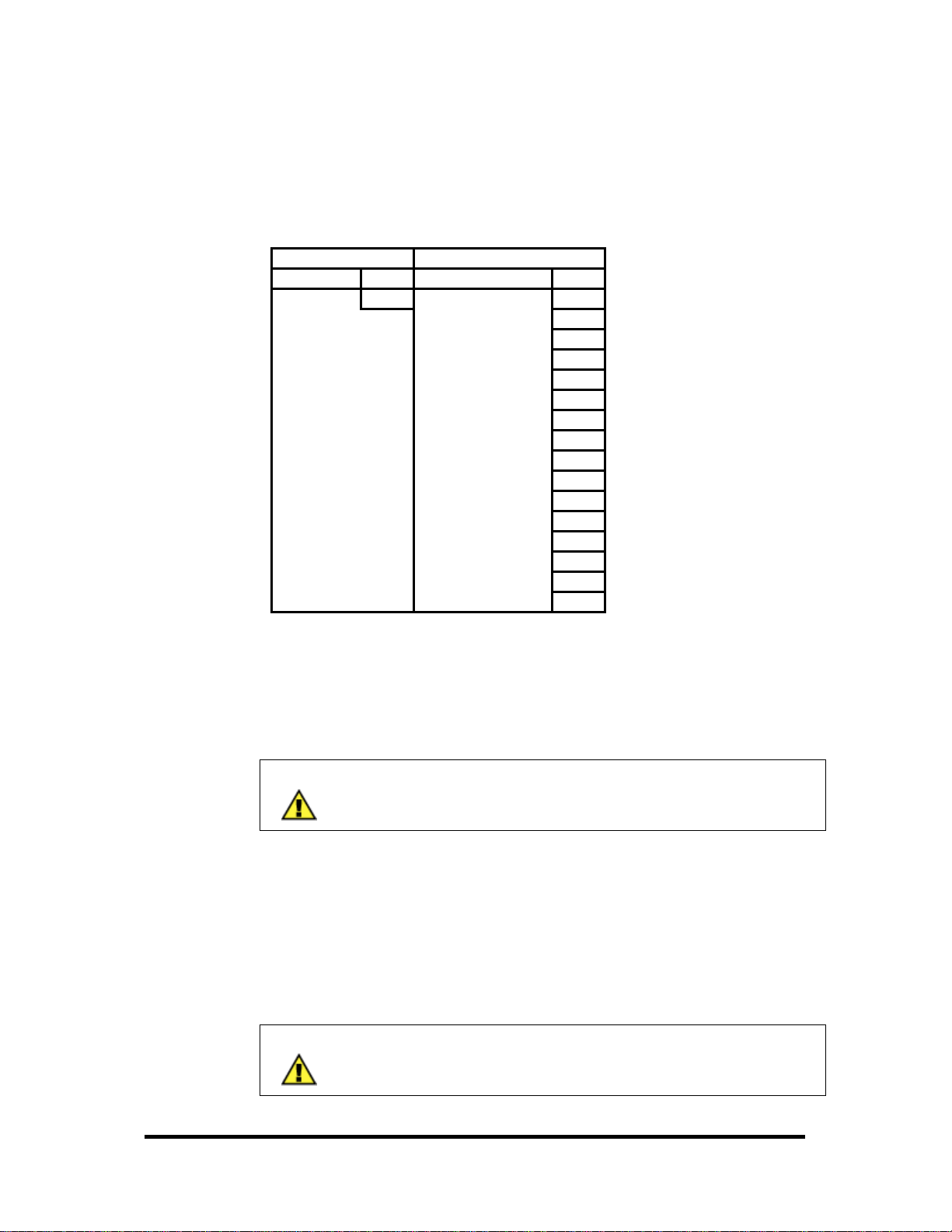
(0x41) Read From Programmable I/O (PIO) Modules
The Read command is used differently for SeaI/O PIO modules. The data, model
number, and configuration are all returned with the state of the module. A sample
Read transaction packet is shown.
Request Response
Field Name (Hex) Field Name (Hex)
Function
Model (lower byte)
Config (channel 2)
Config (channel 1)
Data (Port A1)
Data (Port B1)
Data (Port C1)
Data (Port A2)
Data (Port B2)
Data (Port C2)
Data (Port A3)
Data (Port B3)
Data (Port C3)
Data (port A4)
Data (port B4)
Data (port C4)
41
Function
41
CE
3F
00
AA
55
AA
55
AA
55
AA
55
AA
55
AA
55
Upon a successful Read operation, the SeaI/O module will respond with the
appropriate packet. In this example, the module queried is a SeaI/O-462. The higher
channel is set to all inputs and the lower channel is set to all outputs, with the data
read alternating with 0xAA and 0x55.
NOTE:
Appendix C covers the layout of PIO enabled module registers.
(0x42) Write To PIO Modules
The Write command for a Sealevel SeaI/O PIO module simply sends a request with
function code 0x42 followed by the 12 bytes of data to write. Upon a successful
Write operation, the response packet will be identical to the request.
NOTE:
Appendix C covers the layout of PIO enabled module registers.
© Sealevel Systems, Inc.
- 60 -
SeaI/O User Manual
Page 64

(0x43) Get PIO Config
The Get PIO Config command is used to retrieve the current status of the ports. The
SeaI/O module queried will respond with the model number and the port-by-port I/O
configuration. The module will not respond with any data contained in those ports;
use a Read command to retrieve that information. A sample transaction packet is
shown, below.
Request Response
Field Name (Hex) Field Name (Hex)
Function
Model (lower byte)
Config (channel 2)
Config (channel 1)
NOTE:
Appendix C covers the layout of PIO enabled module registers.
43
Function
43
CE
3F
00
(0x44) Set PIO Config
The Set PIO Config command is used to set the I/O configuration of the ports on a
SeaI/O PIO module. The two most significant bits of each Config channel should be
set to “0”, while the lower six bits determine whether the port will be an input or
output. A bit value of “1” indicates an input and a bit value of “0” indicates an
output.
In this example, channel 2 is set to be all inputs (3F, 00111111), and channel 1 is set
to be all outputs (00, 00000000).
Request Response
Field Name (Hex) Field Name (Hex)
Function
Config (channel 2)
Config (channel 1)
NOTE:
Appendix C covers the layout of PIO enabled module registers.
Function
44
Config (channel 2)
3F
Config (channel 1)
00
44
3F
00
© Sealevel Systems, Inc.
- 61 -
SeaI/O User Manual
Page 65
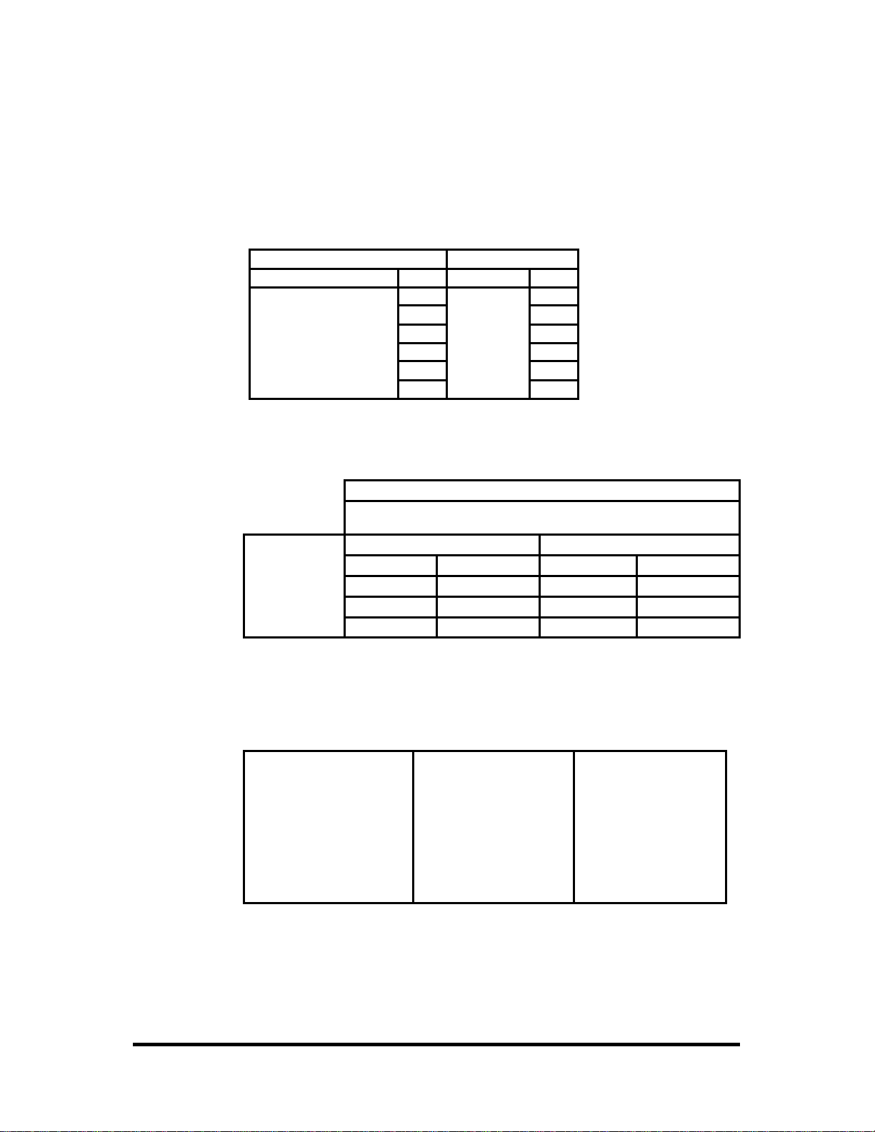
(0x64) Set A/D, D/A Configuration
SeaI/O devices featuring analog to digital or digital to analog conversions can be
configured via a Modbus command. Upon a successful operation, the SeaI/O module
will respond with the response packet shown below.
Request Response
Field Name (Hex) Field Name (Hex)
Function
Device Config
Channels 1-4 Config
Channels 5-8 Config
Channels 9-12 Config
Channels 13-16 Config
The configuration byte stream is defined as follows:
64
00
00
00
00
00
Function
64
BIT 7 BIT 6 BIT
5
BYTE
BIT 4 BIT 3 BIT
2
BIT
1
BIT
0
Device Config A/D Voltage Reference A/D Channel Mode
1-4 Config Ch 1 Range Ch 2 Range Ch 3 Range Ch 4 Range
5-8 Config Ch 5 Range Ch 6 Range Ch 7 Range Ch 8 Range
9-12 Config Ch 9 Range Ch 10 Range Ch 11 Range Ch 12 Range
13-16 Config Ch 13 Range Ch 14 Range Ch 15 Range Ch 16 Range
The actual values for the configuration options above (A/D Voltage Reference, A/D
Channel Mode, and A/D Ch xx Ranges) are enumerated in SeaMaxW32.h, included
with the SeaMAX libraries, and shown in the table below.
A/D Voltage Reference A/D Channel Mode Ch xx Ranges
ANALOG_OFFSET = 0 SINGLE_ENDED = 0 ZERO_TO_FIVE = 0
GND_OFFSET = 1 DIFFERENTIAL = 1 PLS_MIN_FIVE = 1
AD_REF_OFFSET = 2 CURRENT_LOOP = 2 ZERO_TO_TEN = 2
DA_CHANNEL_1 = 4 PLS_MIN_TEN = 3
DA_CHANNEL_2 = 8
© Sealevel Systems, Inc.
- 62 -
SeaI/O User Manual
Page 66

(0x65) Get the A/D, D/A Configuration
Before setting the configuration, it is often useful to retrieve the current configuration
of the SeaI/O module. Modbus command 0x65 will retrieve the settings currently in
use, so that they may be altered and set via command 0x64.
Request Response
Field Name (Hex) Field Name (Hex)
Function
The actual values for the configuration are enumerated in SeaMaxW32.h, included
with the SeaMAX libraries. Upon a successful operation, the SeaI/O module will
respond with the response packet containing the current module configuration.
Function
65
Device Config
Channels 1-4 Config
Channels 5-8 Config
Channels 9-12 Config
Channels 13-16 Config
65
00
00
00
00
00
© Sealevel Systems, Inc.
- 63 -
SeaI/O User Manual
Page 67

Developing Custom Applications Using SeaMAX API
The SeaI/O modules are also designed to work with third party applications. In order
to supplement this development work, Sealevel Systems provides libraries that are
linked into an application and provide an easy interface to the SeaI/O modules. These
libraries are provided for Visual C++ and Visual Basic. The interaction of the
SeaMAX API with SeaI/O modules is shown in the diagram below.
© Sealevel Systems, Inc.
- 64 -
SeaI/O User Manual
Page 68

SeaMAX API
A functional description of each method in the class, including the possible return
values, is provided. All return values less than zero are standard error codes listed
and defined in the standard C library header file <errno.h>. In the following, with the
Object-Oriented model, the Visual C++ DLL is designed as a single class. This class
has the following model:
Open
CSeaMaxW32::Open( unsigned char* filename )
Description
Parameters
Return Codes
Opens the specified resource. The filename parameter can be one
of two different types, Modbus RTU or Modbus TCP.
To specify a Modbus RTU connection (used for all non-Ethernet
enabled modules) the string “sealevel_rtu://COMx” should be
used, where x is a valid COM port number.
To specify a Modbus TCP connection (used only for Ethernet
enabled modules) the string “sealevel_tcp://x.x.x.x” should be
used, where x’s represent the valid IP address of the module to be
accessed.
unsigned char* filename
-38 ENAMETOOLONG The length of the filename is
greater than 256 characters.
-22 EINVAL The specified protocol is invalid,
or, the module could not be
contacted.
-9 EBADF The specified location is invalid
0 Success
Close
CSeaMaxW32::Close( )
Description
Parameters
Return Codes
Closes a previously opened SeaIO module resource.
None
0 Success
© Sealevel Systems, Inc.
- 65 -
SeaI/O User Manual
Page 69

Read
CSeaMaxW32::Read( slave_address_t slaveID, seaio_type_t type, address_loc_t
starting_address, address_range_t range, void* data)
Description
Parameters
Return Codes
Read performs a Modbus read on an opened SeaIO module and
returns the data by reference.
The actual Modbus read type is specified by the ‘type’ argument.
Since Modbus is actually base one, the starting location should be
no less than one. Likewise, the range indicates how many
consecutive inputs should be read.
The final parameter, ‘data’, is a pointer to a buffer in which to
store the returned data – most often, an array of bytes. Consult
the provided code examples for model specific information.
slave_address_t slave_id
seaio_type_t type
address_loc_t starting_address
address_range_t range
-14 EFAULT A Modbus read exception has occurred – the
-22 EINVAL A NULL pointer has been supplied where a
-9 EBADF The specified communication is not currently
-19 ENODEV The SeaIO module did not respond.
≥ 0
void* data
first byte of the data buffer contains the
exception code.
pointer to a data buffer was expected.
established.
Success – The number of valid data bytes in
the buffer.
© Sealevel Systems, Inc.
- 66 -
SeaI/O User Manual
Page 70

Write
CSeaMaxW32::Write( slave_address_t slaveID, seaio_type_t type, address_loc_t
starting_address, address_range_t range, unsigned char*
data)
Description
Parameters
Return Codes
Write performs a Modbus write on an opened SeaIO module and
returns the data by reference.
The actual Modbus write type is specified by the ‘type’ argument.
Since Modbus is actually base one, the starting location should be
no less than one. Likewise, the range indicates how many
consecutive inputs should be read.
The final parameter, ‘data’, is a pointer to a buffer in which to
store the returned data – specifically, an array of bytes. Consult
the provided code examples for model specific information.
slave_address_t slave_id
seaio_type_t type
address_loc_t starting_address
address_range_t range
unsigned char* data
-14 EFAULT A Modbus read exception has occurred – the
first byte of the data buffer contains the
exception code.
-22 EINVAL A NULL pointer has been supplied where a
pointer to a data buffer was expected.
-9 EBADF The specified communication is not currently
established.
-18 EXDEV Can not write data to the outbound
connection – connection error.
-19 ENODEV The SeaIO module did not respond.
-34 ERANGE Attempting to write to more IO points than
are available.
-27 EFBIG Illegal data value
Success – The number of valid data bytes in
≥ 0
the buffer.
© Sealevel Systems, Inc.
- 67 -
SeaI/O User Manual
Page 71

Ioctl
CSeaMaxW32::Ioctl( slave_address_t slaveID, IOCTL_t which, unsigned char *
data)
Description
Parameters
Return Codes
Ioctl has been provided as a muli-function tool to configure and
access non-standard Modbus features of the SeaIO module.
The actual Modbus transaction (and corresponding action) is
specified by the ‘which’ argument. Ioctl can be used to set module
parameters, configure state, and access data. Consult the
provided example source code for model specific information.
The final parameter, ‘data’, is a pointer to a data type which is
appropriate for the particular IOCTL call. Consult the provided
code examples for model specific information.
slave_address_t slave_id
IOCTL_t which
-22 EINVAL A NULL pointer has been supplied where a
≥ 0
void* data
pointer to a data buffer was expected.
Success
( Reference the return values for both Read( ) and Write( ) )
© Sealevel Systems, Inc.
- 68 -
SeaI/O User Manual
Page 72

set_intermessage_delay
CSeaMaxW32::set_intermessage_delay( int delay)
Description
Parameters
Return Codes
This function is used to set the intermessage delay time in effort to
optimize the number of messages that can be sent. This time must
be at least 4 character times long. The default is a function of the
baud rate and should not be changed unless necessary.
The parameter ‘delay’ is the delay (in milliseconds) to wait
between sending back to back messages.
int delay
Success – A Windows HANDLE to the COM resource.
≥ 0
getCommHandle
CSeaMaxW32::getCommHandle( void )
Description
This method may be used to return the HANDLE type data used by
SeaMAX as the communications resource.
Parameters
Return Codes
None
None
© Sealevel Systems, Inc.
- 69 -
SeaI/O User Manual
Page 73

Non Object-Oriented SeaMAX API
The methods following methods have been created to ease use for those more
familiar with non-Object-Oriented or functional design. These functions use the
same parameters as their method counterparts and are used interchangeably.
Before using the functions below, SeaMaxW32Create() should first be called in
order to create a global SeaMAX object and return a pointer as a long data type.
Before the end of program execution, SeaMaxW32Destroy() should be called in
order to clean up the global memory space and release the SeaMAX object.
SeaMaxW32Create
SeaMaxW32Create( void )
Description
Parameters
Return Codes
Creates an instance of the SeaMAX object in the global memory
space.
None
> 0 Success – A long pointer to the SeaMAX
object.
SeaMaxW32Destroy
SeaMaxW32Destroy(CSeaMaxW32* SeaMaxPointer)
Description
Parameters
Return Codes
Releases the globally allocated SeaMAX object.
CSeaMaxW32* SeaMaxPointer
0 Success
© Sealevel Systems, Inc.
- 70 -
SeaI/O User Manual
Page 74

SeaMaxW32Open
SeaMaxW32Open(CSeaMaxW32* SeaMaxPtr, char* filename)
Description
Parameters
Return Codes
See CSeaMaxW32::Open( )
CSeaMaxW32* SeaMaxPointer
See CSeaMaxW32::Open( )
char* filename
SeaMaxW32Close
SeaMaxW32Close(CSeaMaxW32* SeaMaxPointer)
Description
Parameters
Return Codes
See CSeaMaxW32::Close( )
CSeaMaxW32* SeaMaxPointer
See CSeaMaxW32::Close( )
SeaMaxW32Read
SeaMaxW32Read(CSeaMaxW32 *SeaMaxPointer, slave_address_t slaveId,
seaio_type_t type, address_loc_t starting_address,
address_range_t range, void* data)
Description
Parameters
Return Codes
See CSeaMaxW32::Read( )
CSeaMaxW32* SeaMaxPointer
slave_address_t slaveId
seaio_type_t type
address_loc_t starting_address
address_range_t range
See CSeaMaxW32::Read( )
void* data
© Sealevel Systems, Inc.
- 71 -
SeaI/O User Manual
Page 75

SeaMaxW32Write
SeaMaxW32Write(CSeaMaxW32* SeaMaxPointer, slave_address_t slaveId,
seaio_type_t type, address_loc_t starting_address,
address_range_t range, unsigned char* data)
Description
Parameters
Return Codes
See CSeaMaxW32::Write( )
CSeaMaxW32* SeaMaxPointer
slave_address_t slaveId
seaio_type_t type
address_loc_t starting_address
address_range_t range
unsigned char* data
See CSeaMaxW32::Write( )
SeaMaxW32Ioctl
SeaMaxW32Ioctl(CSeaMaxW32* SeaMaxPointer, slave_address_t slaveId,
IOCTL_t which, void* data)
Description
Parameters
See CSeaMaxW32::Ioctl( )
CSeaMaxW32* SeaMaxPointer
slave_address_t slaveId
IOCTL_t which
void* data
Return Codes
See CSeaMaxW32::Ioctl( )
SeaMaxW32GetCommHandle
SeaMaxW32GetCommHandle(CSeaMaxW32* SeaMaxPointer)
Description
Parameters
Return Codes
See CSeaMaxW32::getCommHandle( )
CSeaMaxW32* SeaMaxPointer
See CSeaMaxW32::getCommHandle( )
© Sealevel Systems, Inc.
- 72 -
SeaI/O User Manual
Page 76

IOCTL Calls and Functionality
The Ioctl method allows multiple functions to be implemented through a single,
convienient call. The last parameter of all Ioctl calls is a void pointer – a pointer that
is cast to a particular data type depending on the use of the Ioctl call. Likewise, the
actual Modbus traffic generated depends on the ‘which’ parameter and the type of
Ioctl functionality desired. The following is a list of the Ioctl call types and their
functionality.
Read Module Communications Parameters
Which
Description
Models
Expected
Data Type
Return Codes
IOCTL_READ_COMM_PARAM (1)
Reads the communication parameter, model specific information,
and configuration data from the SeaIO module.
The last parameter is expected to be a pointer to a ‘seaio_ioctl_s’
structure. This structure will be populated with relavent
information regarding the module mode, bridge type, baud rate,
parity.
All the returned information is stored in the ‘seaio_ioctl_s’
structure as a union named ‘params’.
All SeaIO modules
Pointer to a seaio_ioctl_s structure
None
© Sealevel Systems, Inc.
- 73 -
SeaI/O User Manual
Page 77

Set Module Software-Selectable Address
Which
Description
Models
Expected
Data Type
Return Codes
IOCTL_SET_ADDRESS (2)
Sets the SeaIO module’s software selectable address.
The last parameter is expected to be a pointer to a ‘seaio_ioctl_s’
structure. Only one field is used in the structure (u.address) and
should be populated with a valid address before calling Ioctl.
All SeaIO modules
Pointer to a seaio_ioctl_s structure
-22 EINVAL A NULL pointer has been supplied where a
pointer to a data buffer was expected.
Success
≥ 0
( Reference the return values for both Read( ) and Write( ) )
Set Module Baud Rate & Parity
Which
Description
Models
Expected
Data Type
Return Codes
IOCTL_SET_COMM_PARAM (3)
Sets the SeaIO module’s baud rate and parity.
The last parameter is expected to be a pointer to a ‘seaio_ioctl_s’
structure. Two fields are used in the structure
(u.comms.new_baud_rate and u.comms.new_parity) and should be
populated with valid data before calling Ioctl.
All SeaIO modules
Pointer to a seaio_ioctl_s structure
-22 EINVAL A NULL pointer has been supplied where a
pointer to a data buffer was expected.
Success
≥ 0
( Reference the return values for both Read( ) and Write( ) )
© Sealevel Systems, Inc.
- 74 -
SeaI/O User Manual
Page 78

Retrieve Module PIO Configuration
Which
Description
Models
Expected
Data Type
Return Codes
IOCTL_GET_PIO (4)
Requests from the SeaIO module the IO space configuration, as
well as the module model.
The last parameter is expected to be a pointer to a ‘seaio_ioctl_s’
structure. Firstly, the u.pio.model will be populated on return with
an integer representation of the SeaIO module model number.
Secondly, depending on the model, several fields may be
populated. For the 462/463 models, the
u.pio.config_state.PIO96.channel1 and
u.pio.config_state.PIO96.channel2 fields will each contain a onebyte representation of the IO direction of 6 ports.
The ‘Set PIO Config’ section under Modbus commands better
describes the returned data format.
SeaIO 462 / 463
Pointer to a seaio_ioctl_s structure
-22 EINVAL A NULL pointer has been supplied where a
pointer to a data buffer was expected.
Success
≥ 0
( Reference the return values for both Read( ) and Write( ) )
© Sealevel Systems, Inc.
- 75 -
SeaI/O User Manual
Page 79

Set Module PIO Configuration
Which
Description
Models
Expected
Data Type
Return Codes
IOCTL_SET_PIO (5)
Sets the SeaIO module IO space configuration.
The last parameter is expected to be a pointer to a ‘seaio_ioctl_s’
structure. Depending on the model, several fields should be
populated before calling Ioctl.
For the 462/463 models, the u.pio.config_state.PIO96.channel1
and u.pio.config_state.PIO96.channel2 fields should each contain
a one-byte representation of the IO direction of 6 ports.
The ‘Set PIO Config’ section under Modbus commands better
describes the required data format.
SeaIO 462 / 463
Pointer to a seaio_ioctl_s structure
-22 EINVAL A NULL pointer has been supplied where a
pointer to a data buffer was expected.
Success
≥ 0
( Reference the return values for both Read( ) and Write( ) )
© Sealevel Systems, Inc.
- 76 -
SeaI/O User Manual
Page 80

Get Module A/D & D/A Configuration
Which
Description
Models
Expected
Data Type
Return Codes
IOCTL_GET_ADDA_CONFIG (6)
Requests from the SeaIO module the A/D and D/A configuration.
The last parameter is expected to be a pointer to a ‘adda_struct’
structure. On return the adda_struct will contain the software
selectable module A/D configuration and individual channel
voltage ranges.
The ‘Set A/D, D/A Configuration’ section under Modbus
commands better describes the returned data format.
SeaIO 470
Pointer to a adda_struct structure
-22 EINVAL A NULL pointer has been supplied where a
pointer to a data buffer was expected.
Success
≥ 0
( Reference the return values for both Read( ) and Write( ) )
Set Module A/D & D/A Configuration
Which
Description
Models
Expected
Data Type
Return Codes
IOCTL_SET_ADDA_CONFIG (7)
Sets the SeaIO module A/D and D/A configuration.
The last parameter is expected to be a pointer to a populated
‘adda_struct’ structure.
The ‘Set A/D, D/A Configuration’ section under Modbus
commands better describes the required data format.
SeaIO 470
Pointer to a adda_struct structure
-22 EINVAL A NULL pointer has been supplied where a
pointer to a data buffer was expected.
Success
≥ 0
( Reference the return values for both Read( ) and Write( ) )
© Sealevel Systems, Inc.
- 77 -
SeaI/O User Manual
Page 81

Get Module Onboard Hardware Configuration
Which
Description
Models
Expected
Data Type
Return Codes
NOTE
IOCTL_GET_ADDA_EXT_CONFIG (8)
Requests from the SeaIO module the current state of the on-board
A/D and D/A jumper configuration.
The last parameter is expected to be a pointer to a
‘adda_extended_struct’ structure. On return the structure will
contain the state of the hardware jumpers specific to the SeaIO
module.
SeaIO 470
Pointer to a adda_extended_struct structure
-22 EINVAL A NULL pointer has been supplied where a
pointer to a data buffer was expected.
Success
≥ 0
( Reference the return values for both Read( ) and Write( ) )
This particular call determines the on-board jumper settings by
altering many of the outputs, reading the values returned, and
determining the jumper settings required to match the results.
This Ioctl functionality has been provided to determine the hardware
settings on an unknown SeaIO module. If the hardware configuration
is known, this call should be replaced with software coded values due
to the time required to resolve the hardware configuration.
© Sealevel Systems, Inc.
- 78 -
SeaI/O User Manual
Page 82

Using SeaMAX with Visual C++ 6.0
Before using SeaMAX within your Visual C++ 6.0 application, you must add the
include paths and the library paths to help Visual C++ find the libraries. To
configure Visual C++ to use the libraries, open Microsoft Visual C++ 6.0, and click
the ‘Tools’ menu. Click on the ‘Options’ item to select the application options, as
shown below.
© Sealevel Systems, Inc.
- 79 -
SeaI/O User Manual
Page 83

To include the SeaMAX library files, choose the ‘Directories’ tab and select the
‘Include files’ option as shown below. Select the bottom blank line, click the new
entry button, and add your SeaMAX installation directory.
NOTE:
The default SeaMAX installation directory is:
‘C:\Program Files\Sealevel Systems\SeaMAX’
Perform the same operation for the “Library files” option. To add a new folder, click
on the ‘Add’ button, and then click on the ‘(...)’ button to browse to your installation
directory. You are now ready to use SeaMAX in your custom application.
© Sealevel Systems, Inc.
- 80 -
SeaI/O User Manual
Page 84

Using SeaMAX with Visual Basic 6.0
In order to use the SeaMAX library with your Visual Basic program, it will first be
necessary to import the SeaMAX functions using Declare. In each of the example
folders, there exists a file named ‘SeaMAX.bas’ which contains the various type and
function imports.
The following is an example of how to import the various SeaMAX functions into
Visual Basic:
Public Declare Function SeaMaxW32GetCommHandle Lib "CSeaMaxW32.dll" _
(ByVal ptr As Any) As Long
Public Declare Function SeaMaxW32Create Lib "CSeaMaxW32.dll" _
() As Long
Public Declare Function SeaMaxW32Destroy Lib "CSeaMaxW32.dll" _
(ByVal ptr As Any) As Long
Public Declare Function SeaMaxW32Open Lib "CSeaMaxW32.dll" _
(ByVal ptr As Any, _
ByVal portStr As String) As Long
Public Declare Function SeaMaxW32Close Lib "CSeaMaxW32.dll" _
(ByVal ptr As Any) As Long
Public Declare Function SeaMaxW32Read Lib "CSeaMaxW32.dll" _
(ByVal ptr As Any, _
ByVal slaveId As Integer, _
ByVal seaioType As Integer, _
ByVal addressLoc As Integer, _
ByVal addressRange As Integer, _
ByRef readData As Any) As Long
Public Declare Function SeaMaxW32Write Lib "CSeaMaxW32.dll" _
(ByVal ptr As Any, _
ByVal slaveId As Integer, _
ByVal seaioType As Integer, _
ByVal addressLoc As Integer, _
ByVal addressRange As Integer, _
ByRef writeData As Any) As Long
Public Declare Function SeaMaxW32Ioctl Lib "CSeaMaxW32.dll" _
(ByVal ptr As Any, _
ByVal slaveId As Integer, _
ByVal ioctlType As Integer, _
ByRef data As Any) As Long
© Sealevel Systems, Inc.
- 81 -
SeaI/O User Manual
Page 85

Example SeaMAX Programming Tasks
The following is a sampling of the various tasks that can be performed with the
SeaMAX library. For more complete examples, see the provided Visual C++ and
Visual Basic examples installed with the SeaMAX libraries.
NOTE:
The SeaMAX installation places all these examples in the SeaMAX
installation folder. Refer to those examples for more complete and
in-depth information.
Opening/Closing a SeaI/O Module
Whether in C++ or Visual Basic, the process of accessing the SeaMAX libraries
begins with the creation of a SeaMAX object. After creating the SeaMAX object,
Open() can be called with a string argument indicating where the resource exists –
either as COM resource or as a TCP/IP resource.
The following is an example of how to open a COM based SeaI/O module with an
RS-232 bridge, USB bridge, or direct RS-485 connection.
CSeaMaxW32 cw32;
char *portString = “sealevel_rtu://COM6”;
int result = cw32.Open(portString);
For a TCP/IP connection to a SeaI/O module with a Ethernet bridge, the example port
string below is valid. The code below is an example of how to open a TCP/IP
enabled SeaI/O module in Visual Basic.
dim seaMaxPointer as Long
dim portString as String
portString = “sealevel_tcp://10.0.0.1”
seaMaxPointer = SeaMaxW32Create()
returnValue = SeaMaxW32Open(seaMaxPointer, portString)
© Sealevel Systems, Inc.
- 82 -
SeaI/O User Manual
Page 86

Reading From Inputs / Outputs
In order to read from the inputs or outputs, the SeaIO module must first be opened
successfully. The VC++ example below shows how to read in four inputs, starting at
input 3 and continuing until input 6. In this case, since we are not reading in a full 8
bits, the data will be present in the lowest order bits of the data array.
unsigned char data[1] = {0};
int slaveId = 247
int type = D_INPUTS;
int start = 3;
int range = 4;
result = cw32.Read(slaveId, type, start, range, data);
Reading in inputs within Visual Basic is similar; D_INPUTS is the read type required
for either language to access the inputs. The example below shows how it can be
done through VB. If the current status of the outputs is required, a read can be
performed using the COILS type.
dim slaveId, startLoc, range as Integer
dim recvData(2) as Byte
slaveId = 247
startLoc = 1
range = 16
returnValue = SeaMaxW32Read(seaMaxPointer, slaveId, D_INPUTS, _
startLoc, range, recvData(0))
Writing to Outputs
Writing outputs is similar to reading inputs, with the single exception that
Write or SeaMaxW32Write is called instead of Read. The two examples
below show how to write to digital outputs using Write and
SeaMaxW32Write in Visual C++ and Visual Basic, respectively.
result = cw32.Write(slaveId, COILS, start, range, data);
returnValue = SeaMaxW32Write(seaMaxPointer, slaveId, COILS, startLoc,
range, sendData(0))
© Sealevel Systems, Inc.
- 83 -
SeaI/O User Manual
Page 87

Changing the Programmable I/O Configuration
For SeaI/O modules featuring programmable IO, it may be necessary to configure the
IO direction and presets from a custom application, rather than through MaxSSD.
In such a case, the holding registers hold the module IO configuration. Specifically,
holding registers 4 – 9 contain the bit presets for the module. However, these
registers must be written singly, rather than performing a multi-register write (i.e.
only one register should be written to at a time). Please note that holding registers
are two bytes wide, each.
After the bit presets have been written, the IO direction can be set by writing to
holding register three. For more information, consult the section labeled “Set PIO
Config” and the appendix section titled “Model 462/463 Holding Registers.”
result = cw32.Write(slaveId, HOLDINGREG, 4 + index, 1,
&writeHoldRegs[index]);
result = cw32.Write(slaveId, HOLDINGREG, 3, 1, &writeHoldRegs[0]
The following is an example of how to set the holding registers within a Visual Basic
application.
returnValue = SeaMaxW32Write(seaMaxPointer, slaveId, HOLDINGREG, 4 +
Counter, 1, writeHoldRegs(i))
returnValue = SeaMaxW32Write(seaMaxPointer, slaveId, HOLDINGREG, 3, 1,
writeHoldRegs(0))
NOTE:
Each group of 8 PIO is considered a port. Ports may be set either as
a group of inputs or a group of outputs – with bit selectable presets
for ports configured as outputs.
NOTE:
The output port presets do not define a constant state for the output
ports. Rather, the presets indicate the default state for when the
ports change IO directions (i.e. from input to output) or when the
device is reset.
© Sealevel Systems, Inc.
- 84 -
SeaI/O User Manual
Page 88

Reading from Analog Inputs
In order to read from an A/D channel, SeaMAX requires that an input register read
occurs – much like a discreet input read is required to read the digital input. It’s
important to note that a read of input register type requires that there be 2 bytes of
available space allocated for each register being read. The example below
exemplifies an input register read from within Visual C++.
result = cw32.Read(slaveId, INPUTREG, start, range, ad_input);
Following is an example of an input register read performed within a Visual Basic
application.
returnValue = SeaMaxW32Read(seaMaxPointer, slaveId, INPUTREG, startLoc,
range, recvData(0))
The data returned by the Read function is only a binary value. In order to translate
the data into a meaningful unit such as Volts or milliamps, refer to the example
documentation provided within the SeaMAX installation.
Writing to Analog Outputs
Similar to reading from an A/D channel, writing to an analog output occurs by
issuing a holding register write. Holding registers are two bytes wide and require that
the data be available in Big Endian format.
result = cw32.Write(slaveId, HOLDINGREG, start, range, da_output);
The following example shows how to write to a holding register within Visual Basic.
returnValue = SeaMaxW32Write(seaMaxPointer, slaveId, HOLDINGREG,
startLoc, range, sendData(0))
Similar to reading A/D values, in order to convert a desired Voltage value into the
appropriate Write data, consult the examples installed with the SeaMAX installation.
© Sealevel Systems, Inc.
- 85 -
SeaI/O User Manual
Page 89

Configuring A/D or D/A Channels
In order to read the A/D channels properly, it is often necessary to first configure
them to be within the proper voltage ranges. The following VC++ example shows
how to get the current device configuration via an Ioctl call, adjust the channel and
device settings, and then commit those changes back to the SeaIO module.
adda_ext_config extended_configuration;
result = cw32.Ioctl(slaveId, IOCTL_GET_ADDA_EXT_CONFIG,
&extended_configuration);
configuration.device.reference_offset = ANALOG_OFFSET;
configuration.device.channel_mode = SINGLE_ENDED;
configuration.channels.ch_1 = PLS_MIN_TEN;
result = cw32.Ioctl(slaveId, IOCTL_SET_ADDA_CONFIG, &configuration);
In the example above, the device was set to measure the analog inputs as 16 singleended inputs and the first channel was configured to be within the plus or minus 10
Volt range. In the Visual Basic example below, however, the device has been
configured to read the analog inputs in current loop mode and channel 1 has been
configured to the zero to five Volt range.
Dim configuration As adda_config
returnValue = SeaMaxW32Ioctl(seaMaxPointer, slaveId,
IOCTL_GET_ADDA_CONFIG, configuration)
configuration.device.reference_offset = ANALOG_OFFSET
configuration.device.channel_mode = SINGLE_ENDED
configuration.channels.ch_1 = PLS_MIN_TEN
returnValue = SeaMaxW32Ioctl(seaMaxPointer, slaveId,
IOCTL_SET_ADDA_CONFIG, configuration)
NOTE:
Please note that when setting the configuration, all channel ranges
are set concurrently on an Ioctl set configuration call. In order to
change a single channel’s configuration, the current configuration
must be requested, altered, and then reset.
© Sealevel Systems, Inc.
- 86 -
SeaI/O User Manual
Page 90

CEthernet API
The CEthernet API is designed as an extension library that enables programmers to
develop applications to automatically find, configure, and use Ethernet-enabled
Sealevel devices. This library removes the manual hard-coding requirement of
locating a device on the network and replaces it with an automatic search function.
The CEthernet Development Libraries support the SeaI/O (Digital I/O) E-series and
SeaLINK (Ethernet Serial Servers) product families.
The source code contained in this document is designed to offer a high-level
overview of how to utilize the libraries contained on the Sealevel software CD-ROM
that ships with all SeaI/O modules. These code segments are meant as examples to
assist in your application development. Contact technical support regarding any
questions about the included code segments.
NOTE:
This library is not required to use any Sealevel Ethernet device.
© Sealevel Systems, Inc.
- 87 -
SeaI/O User Manual
Page 91
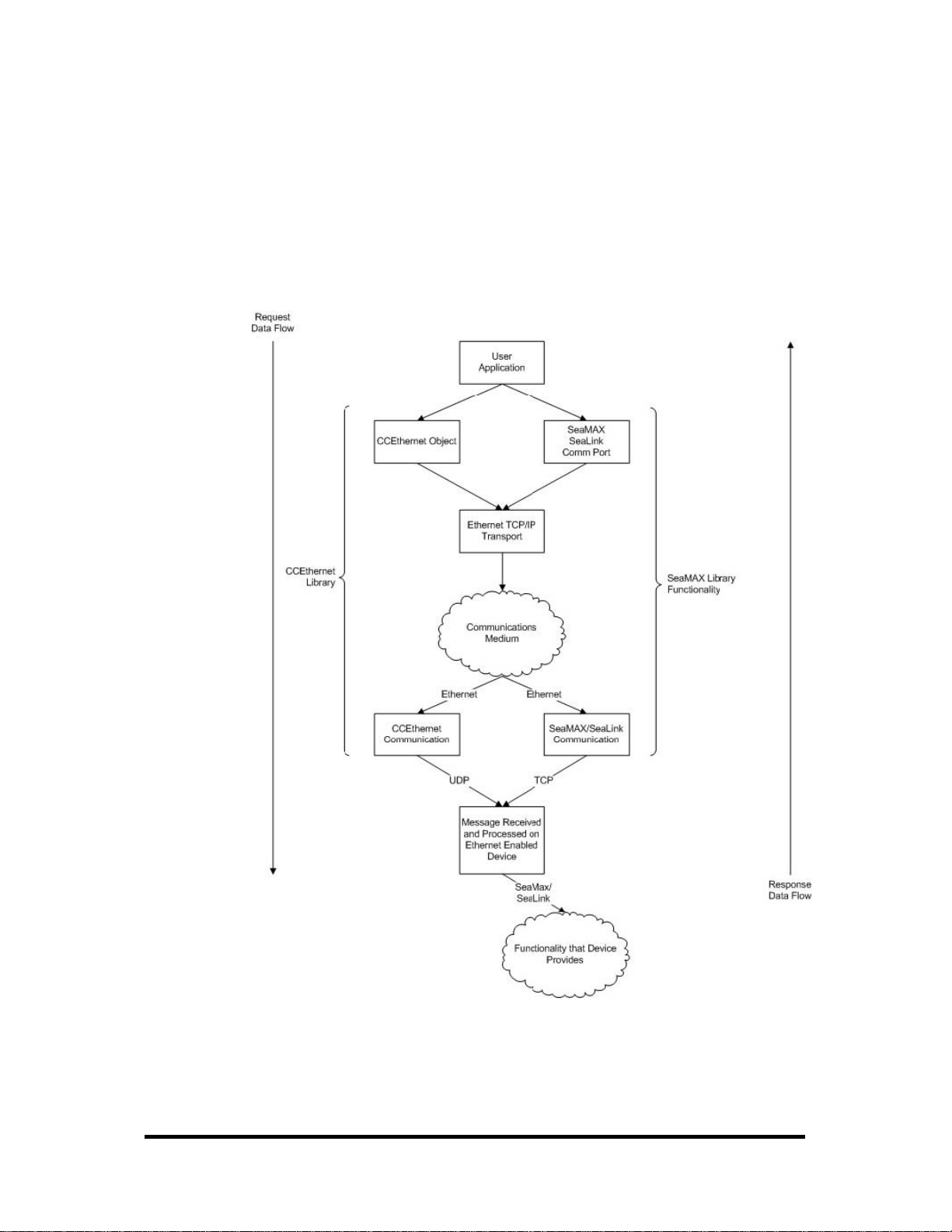
CEthernet Architecture
The diagram below is a high-level overview of how the CEthernet Library co-exists
with other libraries, such as SeaMAX, to communicate with Ethernet-enabled
devices. As stated in the introduction, this is a supplementary library and is not
required for the device to be functional. All packets from the CEthernet library are
UDP based.
Flow Model for Ethernet Enabled Devices
© Sealevel Systems, Inc.
- 88 -
SeaI/O User Manual
Page 92

CEthernet API
find_devices
The API to CCEthernet is easy to use, straightforward, and designed to be as userfriendly as possible. Looking at the UML diagram, one can determine that there are
only six functions that the interface provides. Of those, only four are required for
basic operation. Sample code segments are provided in a later section. Each of the
methods are documented below, including the parameters and the associated return
codes.
CCEthernet
-array
+CE
-objs
+CCEthernet()
+~CCEthernet()
+Alloc(in number : int)
+find_devices(in type_to_find : ceth_device_type, in number_to_find : int, inout list_to_store_devices : ceth_device *)
+Free(inout list : ceth_device *)
+get_number_of_interfaces()
+isWinsockInitialized()
-prepareList(inout c : ceth_device *, in n : int)
+set_information(inout device : ceth_device *, in command : ceth_set_types, in ... : ...)
UML Class Model for CCEthernet
Parameters
type_to_find
− Can be: SeaIO_Ethernet, SeaLink_Dev, or Sealevel_All_Devices.
number_to_find
− number <= number allocated using Alloc().
list_to_store_devices
− pointer to the list previously allocated.
Return Values
-100XX
− Socket Error. Refer to Winsock documentation for error code.
© Sealevel Systems, Inc.
- 89 -
SeaI/O User Manual
Page 93

set_information
Parameters
device
− The device to modify the parameters of
command
− which parameters to modify, (SetIPAddress, SetDHCP, SetName).
...
− This list is based off the command parameter above. For more information,
see below.
The variable argument list above, (denoted by the ...) is defined by which command
parameter is passed in. The commands can be logically OR'd together to make the
sequence easier. First, each command individually:
SetIPAddress
− New IP Address
− New Netmask
− New Gateway
SetDHCP
− None
SetName
− New Name
If the IP configuration (DHCP or Static) is logically OR'd with the SetName option,
the parameters for the IP address must come first, and the last parameter will be the
name.
Return Values
-100XX
− Socket Error. Refer to Winsock documentation for error code.
© Sealevel Systems, Inc.
- 90 -
SeaI/O User Manual
Page 94

Alloc
Free
Parameters
number
− Number of devices to allocate space for. allocated.
Return Values
> 0
− Valid list.
-ENOMEM
− Error allocating memory.
Parameters
list
− Pointer to the list previously allocated.
Return Values
None
NOTE:
Because the allocation masks much of the socket communication,
the interface provides a mechanism to allocate and free the device
structures. It will not automatically perform this operation and use
of this library requires the explicit calls to Alloc() and Free().
© Sealevel Systems, Inc.
- 91 -
SeaI/O User Manual
Page 95

CEthernet Application Development
Using Visual C++
To use the CCEthernet Class, simply ensure that the SeaMAX directory is in the
include and library path for Visual C++. Once that is complete, simply include the
CEthernet.lib file is contained on the link tab settings for the project.
Required Code
For all of the following examples, the following must be in either the StdAfx.h file if
using Precompiled Header Files (PCH) or at the top of the individual C++ file. Once
these files are added, the code will know the definitions and locations for the
provided library.
#include <stdio.h>
#include <windows.h>
#include <stdlib.h>
#include "CEthernet.h"
© Sealevel Systems, Inc.
- 92 -
SeaI/O User Manual
Page 96

Simple Find Using print_info Function
This section will show a simple find on all Sealevel Devices. There is a helper
function that is used to print out the information discovered about each unit. The
source code segment for the helper function is listed below.
void print_info(ceth_device_p c)
{
printf("Type : %s\n",
c->type==SeaIO_Ethernet?"SeaIO Ethernet"
:c->type==SeaLink_Dev?"SeaLink Device"
:"Who Knows?");
printf("Mac : %2.2X:%2.2X:%2.2X:%2.2X:%2.2X:%2.2X\n",
c->mac_address.c[0],
c->mac_address.c[1],
c->mac_address.c[2],
c->mac_address.c[3],
c->mac_address.c[4],
c->mac_address.c[5]);
printf("IP : %d.%d.%d.%d\n",c->ip_address.c[0],
c->ip_address.c[1],
c->ip_address.c[2],
c->ip_address.c[3]);
printf("NetMask : %d.%d.%d.%d\n",c->net_mask.c[0],
c->net_mask.c[1],
c->net_mask.c[2],
c->net_mask.c[3]);
if(c->gateway.i == 0)
{
printf("Gateway: Not Set\n");
}
else
{
printf("Gateway : %d.%d.%d.%d\n",c->gateway.c[0],
c->gateway.c[1],
c->gateway.c[2],
c->gateway.c[3]);
printf("Name : %s\n",c->name);
printf("DHCP Enabled? : %s\n",
c->dhcp_enabled?"Yes":"No");
}
© Sealevel Systems, Inc.
- 93 -
SeaI/O User Manual
Page 97

Finding All Devices
This simple code segment issues a find on all devices and then prints out each device
using the print_info function code segment from the previous page.
This code segment allocates space for ten devices and then performs a find for
devices. If the return code is greater than zero, then the function successfully found
the number of devices returned.
Notice that we have to explicitly Free() the allocated buffers, and then delete the class
for proper memory management.
int main(int argc, char* argv[])
{
CCEthernet *a;
ceth_device_p b;
ceth_device_p d;
int c;
int i;
a = new CCEthernet();
b = a->Alloc(10);
c=a->find_devices(Sealevel_All_Devices,10,b);
if(c<0)
{
printf("Error %d\n",c);
goto end;
}
printf("Found %d\n",c);
d=b;
for(i=0;i<c;i++)
{
dump_out(d);
d++;
}
end:
a->Free(b);
delete(a);
return 0;
}
© Sealevel Systems, Inc.
- 94 -
SeaI/O User Manual
Page 98
Appendix A – Data Encoding Tables
These tables help to decode Get Config responses from Sealevel SeaI/O modules. A
Get Config response contains five bytes in the following order:
Model Number Baud Rate Bridge Type Parity Magic Cookie
For more information, refer to the Get Config request explained in the Extended
Modbus Command Set section of this manual.
Model Numbers
Result Model
9A 410x
A4 420x
AE 430x
B8 440x
C2 450x
CE 462x
CF 463x
D6 470x
00
NOTE:
See Note
A ‘Get’ request (0x45) resulting in (00) means that a ‘Get
Extended Module Information’ (0x66) request should be
performed to retrieve the actual device number.
Refer to the Extended Modbus Command section of this manual
for additional information.
Result Baud Rate
Baud Rates
01 1200
02 2400
03 4800
04 9600
05 14.4K
06 19.2K
07 28.8K
08 38.4K
09 57.6K
0A 115.2K
Bridge Types
Result Bridge
00 RS-485
01 Ethernet
02 USB
03 RS-232
04 Expansion Unit
© Sealevel Systems, Inc.
- 95 -
Parity
Result Parity
00 None
01 Odd
02 Even
SeaI/O User Manual
Page 99

Appendix B – CRC Calculation
To further illustrate the example shown in the CRC-16 section, the algorithm for
generating the CRC-16 is shown below.
unsigned short calc_crc(int n,unsigned char *outbound_message)
{
unsigned char carry_flag;
unsigned short crc=0xFFFF;
for (int i = 0; i < n; i++)
{
crc = crc ^ outbound_message[i];
for (int j = 0; j < 8; j++)
{
carry_flag = crc & 0x01;
crc = crc >> 1;
if (carry_flag == 1)
{
crc = crc ^ 0xA001;
}
}
}
return crc;
}
© Sealevel Systems, Inc.
- 96 -
SeaI/O User Manual
Page 100

Appendix C – SeaIO Model 462/463 Holding Register Set
Register 8 bits 8 bits
1 Bridge Type Model Number
Standard
4 bits 4 bits 8 bits
2 Baud Rate Parity Address
Port 4 Port 3 Port 2 Port 1
C B A C B A C B A C B A
3 0 0 X X X X X X 0 0 X X X X X X
Port B1 Port A1
Default Default
4 X X X X X X X X X X X X X X X X
Port A2 Port C1
Default Default
Default
Configuration
State
(46X Only)
5 X X X X X X X X X X X X X X X X
Port C2 Port B2
Default Default
6 X X X X X X X X X X X X X X X X
Port B3 Port A3
Default Default
7 X X X X X X X X X X X X X X X X
Port A4 Port C3
Default Default
8 X X X X X X X X X X X X X X X X
Port C4 Port B4
Default Default
9 X X X X X X X X X X X X X X X X
15 0
Default
Power-On
Bit Presets
(46X Only)
© Sealevel Systems, Inc.
- 97 -
SeaI/O User Manual
 Loading...