

Page 1

ULTRA COMM+422™
USER MANUAL
Part #3055
Sealevel Systems, Inc. Telephone: (864) 843-4343
PO Box 830 Fax: (864) 843-3067
Liberty, SC 29657 USA www.sealevel.com
Page 2

Contents
INTRODUCTION ........................................................................ 1
OVERVIEW......................................................................................1
WHAT’S INCLUDED ........................................................................1
FACTORY DEFAULT SETTINGS ........................................................1
CARD SETUP ............................................................................ 2
ADDRESS SELECTION......................................................................2
JUMPER SELECTIONS ......................................................................4
IRQ Selection..............................................................................4
INTERRUPT MODES.........................................................................5
RS-485 ENABLE MODES ................................................................6
Interface Mode Examples J1D – J4D .........................................7
Interface Mode Examples J1D – J4D (continued) ......................8
LINE TERMINATION ........................................................................9
CLOCK MODES .............................................................................10
BAUD RATES AND DIVISORS FOR THE ‘DIV1’ MODE .....................11
BAUD RATES AND DIVISORS FOR THE ‘DIV2’ MODE .....................12
INSTALLATION ....................................................................... 13
OPERATING SYSTEM INSTALLATION .............................................13
For Windows Users ..................................................................13
Other Operating Systems ..........................................................13
TECHNICAL DESCRIPTION .................................................... 14
FEATURES.....................................................................................14
INTERRUPTS .................................................................................15
WHY USE AN ISP? ........................................................................16
CONNECTOR PIN ASSIGNMENTS ...................................................17
DB-9 Pin Assignments.............................................................. 17
DB-37 Connector Pin Assignments ..........................................17
SPECIFICATIONS .................................................................... 18
ENVIRONMENTAL SPECIFICATIONS ............................................... 18
MANUFACTURING.........................................................................18
POWER CONSUMPTION .................................................................18
MEAN TIME BETWEEN FAILURES (MTBF)...................................18
PHYSICAL DIMENSIONS ................................................................18
A
PPENDIX A - TROUBLESHOOTING ...................................... 19
PPENDIX B - HOW TO GET ASSISTANCE............................ 21
A
A
PPENDIX C - ELECTRICAL INTERFACE .............................. 22
RS-422......................................................................................... 22
RS-485......................................................................................... 22
Page 3

APPENDIX D - ASYNCHRONOUS COMMUNICATIONS ............ 23
APPENDIX E - SILK-SCREEN ................................................. 24
APPENDIX F - COMPLIANCE NOTICES .................................. 25
FEDERAL COMMUNICATIONS COMMISSION STATEMENT .............. 25
EMC DIRECTIVE STATEMENT ......................................................25
WARRANTY............................................................................ 26
Figures
Figure 1 - Available Address Combinations............................................2
Figure 2 - Address Selection Table...........................................................3
Figure 3 - Port to Connector Table ..........................................................3
Figure 4 - Header J1A, Normal IRQ Mode ............................................. 5
Figure 5 - Header J1A & J2A, Shared IRQ Mode..................................5
Figure 6- Headers J1D- J4D, RS-422 .......................................................7
Figure 7 - Headers J1D- J4D, RS-485 ‘Auto’ Enabled, with ‘No Echo’7
Figure 8 - Headers J1D- J4D, RS-485 ‘Auto’ Enabled, with ‘Echo’ .....7
Figure 9 - Headers J1D- J4D, RS-485 ‘RTS’ Enabled, with ‘No Echo’ 8
Figure 10 - Headers J1D- J4D, RS-485 ‘RTS’ Enabled, with ‘Echo’ .... 8
Figure 11 - Headers J1E - J4E, Line Termination ..................................9
Figure 12 - Clocking Mode 'Divide By 4’...............................................10
Figure 13 - Clocking Mode 'Divide By 2’...............................................10
Figure 14 - Clocking Mode 'Divide By 1’...............................................10
Figure 15 - Asynchronous Communications Bit Diagram....................23
©Sealevel Systems, Inc.
SL9146 Revision 7/2006
Sealevel Systems, Incorporated. All rights reserved.
Page 4
Introduction
Introduction
Overview
The Sealevel Systems ULTRA COMM+422 provides the PC with four
additional RS-422/485 serial ports for terminals, modems, printers, etc.
The unique feature of the ULTRA COMM+422 is the ability to be RS-485
compatible without the need for special software or drivers. This ability is
especially useful in Windows, Windows NT, and OS/2 environments where the
lower level I/O control is abstracted from the application program. This ability
means that the user can effectively use the ULTRA COMM+422 in an RS-485
application with existing (i.e. standard RS-232) software drivers.
Note: The ‘Auto Enable’ feature is not available on the p/n 3441.
What’s Included
The ULTRA COMM+422 is shipped with the following items. If any of these
items are missing or damaged, contact the supplier.
• ULTRA COMM+422 Serial I/O Adapter
• DB-37 to four DB-9 ‘Spider Cable’
• Sealevel Software
Factory Default Settings
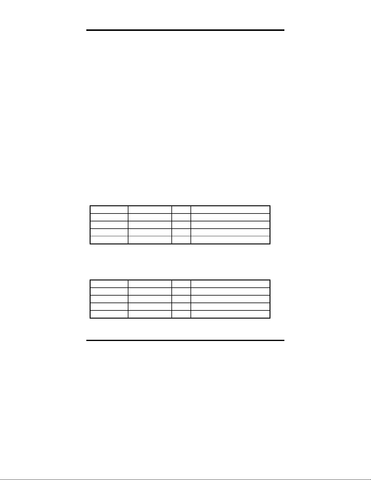
The ULTRA COMM+422 factory default settings are as follows:
Port # Base Address IRQ Electrical Specification
Port 1 280 10 RS-422
Port 2 288 5 RS-422
Port 3 290 10 RS-422
Port 4 298 5 RS-422
To install the ULTRA COMM+422 using factory default settings, refer to
Installation on page 13.
For your reference, record installed ULTRA COMM+422 settings below:
Port # Base Address IRQ Electrical Specification
Port 1
Port 2
Port 3
Port 4
Sealevel Systems ULTRA COMM+422 Page 1
Page 5

Card Setup
Card Setup
The ULTRA COMM+422 contains several jumper straps, which must be set for
proper operation.
Address Selection
Each port on the ULTRA COMM+422 occupies eight consecutive I/O
locations. A DIP-switch is used to set the base address for these locations.
The ULTRA COMM+422 has a unique addressing scheme that allows it to be
completely compatible with Sealevel Systems’ older four port RS-422/485
interface adapter (p/n 3067) and provide for the ability to select address
combinations more commonly used.
The first addressing scheme allows the ULTRA COMM+422 to select the
addresses for its ports from a table of available address combinations.
The following table shows the addressing combinations available. If different
address combinations are required, please contact Sealevel Systems Technical
Support about a custom PAL option.
Switch6 Switch7 Switch8 Port
1
On On Off 3F8 2F8 3E8 2E8
On Off On 2F8 3E8 2E8 2E0
On Off Off 3E8 2E8 280 288
Off On On 500 508 510 518
Off On Off 580 588 590 598
Off Off On 1500 1508 1510 1518
Off Off Off 3220 3228 4220 4228
On On On Addresses set up by switches 1-5
Figure 1 - Available Address Combinations
Note: Each COM: port in the system should have a unique address. Typically
COM1: - COM4: addresses are 3F8, 2F8, 3E8 and 2E8 Hex.
Refer to Appendix A for common address contentions.
Sealevel Systems ULTRA COMM+422 Page 2
Port
2
Port
3
Port
4
Page 6
Card Setup
The second mode of address selection provides the compatibility mode. In this
mode the DIP-switch sets the base address and the adapter occupies 32
consecutive I/O locations. The following table illustrates the location of each
port and its relationship to the other ports.
Note: For switches 1 - 5 to become active, switches 6, 7 & 8 must be set in the
‘On’ or ‘Up’ position.
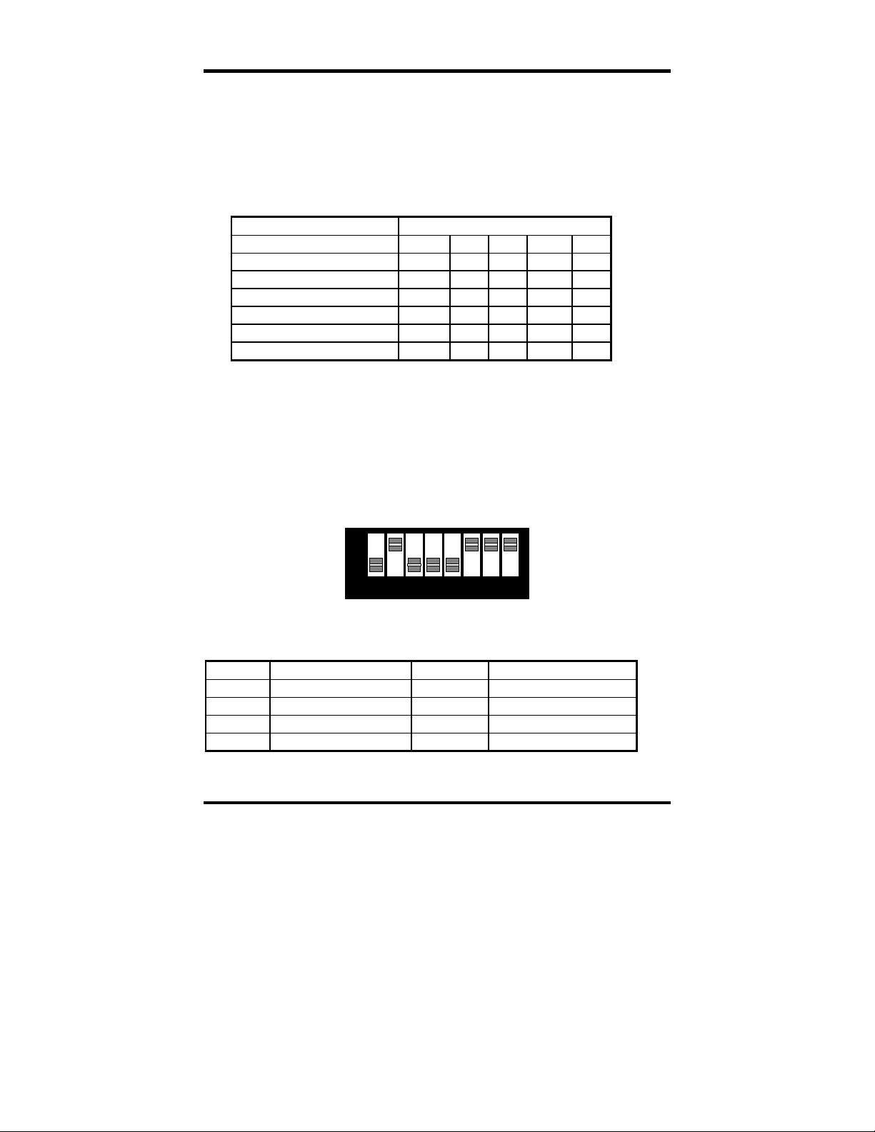
Switch Settings
Address lines Æ A9 A8 A7 A6 A5
Address Selected 1 2 3 4 5
280-29F Off On Off On On
2A0-2BF Off On Off On Off
380-39F Off Off Off On On
1A0-1BF On Off Off On Off
2E0-2FF Off On Off Off Off
Figure 2 - Address Selection Table
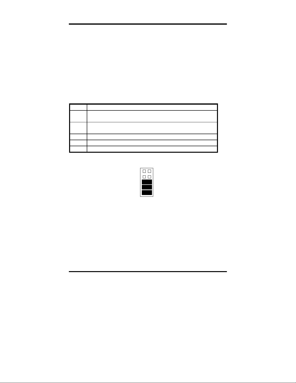
The following illustration shows the correlation between the DIP-switch setting
and the address bits used to determine the base address. In the example below,
address 2E0 is selected as a base. Address 2E0 in binary is XX 10 111X XXXX
where X = a non-selectable address bit.
A9 A5
ON
OFF
1 2 3 4 5 6 7
Port # Connector Location Address Example (Base=2E0)
1
2
3
4
Sealevel Systems ULTRA COMM+422 Page 3
1 Base+0 2E0-2E7
2 Base+8 2E8-2EF
3 Base+16 2F0-2F7
4 Base+24 2F8-2FF
Figure 3 - Port to Connector Table
8
Page 7
Card Setup
Jumper Selections
For ease of configuration, the headers are grouped by port. Port one headers
have a ‘J1’ prefix; Port two headers have the ‘J2’ prefix, etc. For example, the
header that controls the Port one IRQ selection is J1B; the header that controls
the Port 2 IRQ selection is J2B. The silk-screen also provides information for
configuring the adapter without the use of the manual. This is particularly useful
in field re-configuration.
IRQ Selection
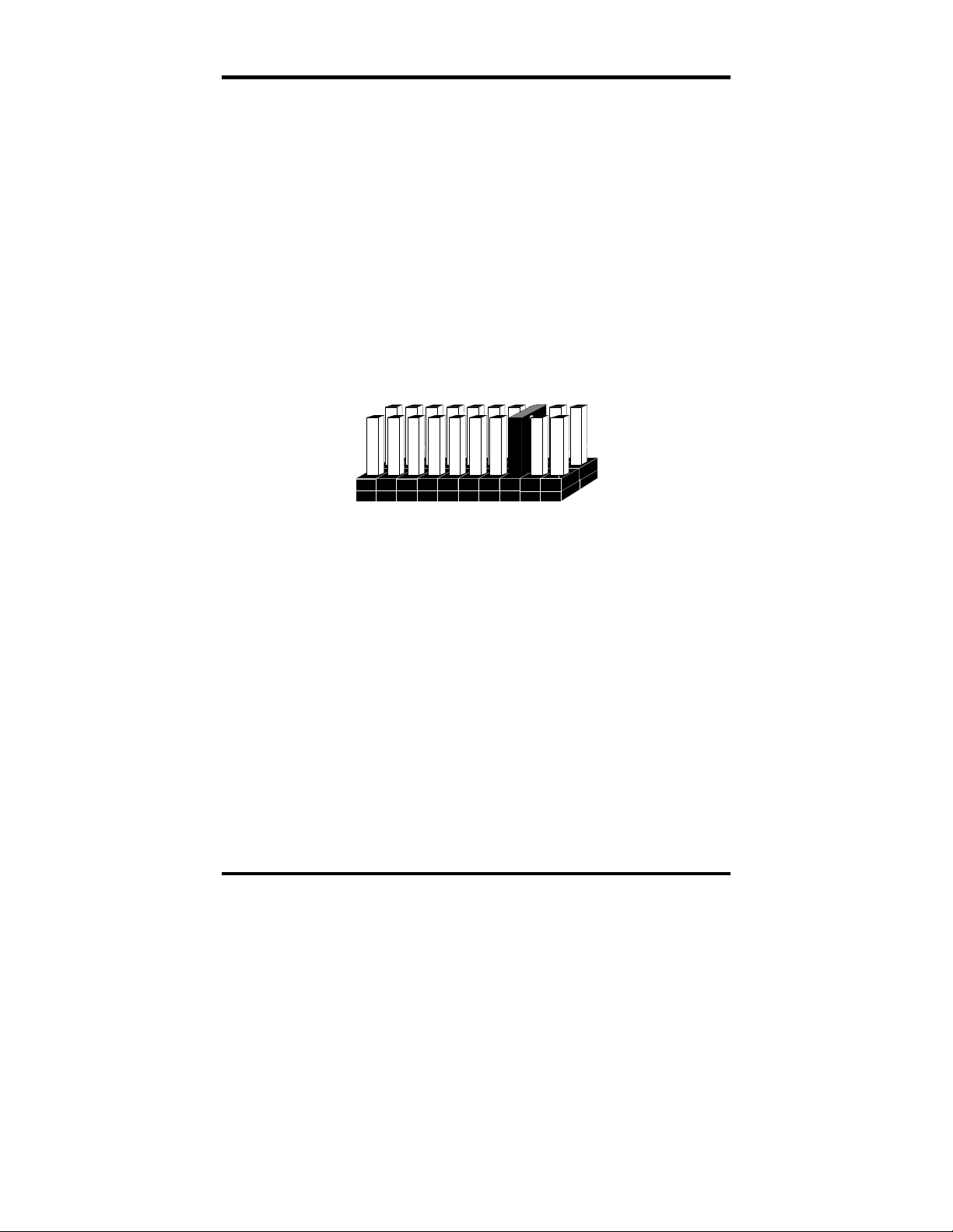
Headers J1B through J4B select the interrupt request for each serial port. If
COM1: is selected, the corresponding jumper must be on the IRQ4 setting. If
COM2: is selected, the corresponding jumper must be on IRQ3.
34567 101112159
Figure 4 – Headers J1B – J4B, IRQ Selection
Note: Most communications software applications default COM3: to IRQ4 and
COM4: to IRQ3. This requires the sharing of interrupts between COM1:
and COM3:, and between COM2: and COM4:. While this is the default, it
is not always the preferred setting. Check your software configuration
instructions to determine the most appropriate IRQ selection.
Any two or more ports can share a common IRQ by placing the jumpers on the
same IRQ setting and setting the appropriate selections at J1A through J4A.
Consult your particular software for IRQ selection. If no interrupt is desired,
remove the jumper.
Sealevel Systems ULTRA COMM+422 Page 4
Page 8
Card Setup
Interrupt Modes
Headers J1A through J4A select the interrupt modes for each port. Each port
must be set in the correct mode to insure proper operation.
‘N’ indicates the (N)ormal, single interrupt per port mode. ‘S’ Indicates the
(S)hared interrupt mode, which allows more than one port to access a single
IRQ. ‘M’ indicates the inclusion of a 1K ohm pull-down resistor required on one
port when sharing interrupts.
J1A
NM
Figure 4 - Header J1A, Normal IRQ Mode
Set the jumpers to ‘S’ for shared interrupt mode on all blocks sharing an IRQ
except one. Set that port block for ‘M’. This provides the pull-down resistor
circuit that makes sharing IRQs possible. If you are using more than one
ULTRA COMM+422 or a compatible adapter in a bus you should only have
one port set to ‘M’. The following example shows two ports sharing a single
IRQ.
S
J1A
NSM
J2A
NSM
Figure 5 - Header J1A & J2A, Shared IRQ Mode
Set the jumper to ‘S’ if you are using more than one ULTRA COMM+422 in a
bus or to completely remove the pull-down resistor for hardware compatibility.
Setting the adapter in this configuration when it is not accompanied by a
pull-down resistor will prevent the ports from triggering an interrupt.
Sealevel Systems ULTRA COMM+422 Page 5
Page 9

Card Setup
RS-485 Enable Modes
RS-485 is ideal for multi-drop or network environments. RS-485 requires a
tri-state driver (not dual-state) that will allow the electrical presence of the driver
to be removed from the line. The driver is in a tri-state or high impedance
condition when this occurs. Only one driver may be active at a time and the other
driver(s) must be tri-stated. The output modem control signal Request To Send
(RTS) is typically used to control the state of the driver. Some communication
software packages refer to RS-485 as RTS enable or RTS block mode transfer.
One of the unique features of the ULTRA COMM+422 is the ability to be RS485 compatible without the need for special software or drivers. This ability is
especially useful in Windows, Windows NT, and OS/2 environments where the
lower level I/O control is abstracted from the application program. This ability
means that the user can effectively use the ULTRA COMM+422 in an RS-485
application with existing (i.e. standard RS-232) software drivers.
Headers J1D through J4D are used to control the RS-485 mode functions for the
driver circuit. The selections are ‘RTS’ enable (silk-screen ‘RT’) or ‘Auto’
enable (silk-screen ‘AT’). The ‘Auto’ enable feature automatically
enables/disables the RS-485 interface. The ‘RTS’ mode uses the ‘RTS’ modem
control signal to enable the RS-485 interface and provides backward
compatibility with existing software products.
Position 3 (silk-screen ‘NE’) of J1D through J4D is used to control the RS-485
enable/disable functions for the receiver circuit and determine the state of the
RS-422/485 driver. The RS-485 ‘Echo’ is the result of connecting the receiver
inputs to the transmitter outputs. Every time a character is transmitted, it is also
received. This can be beneficial if the software can handle echoing (i.e. using
received characters to throttle the transmitter) or it can confuse the system if the
software does not. To select the ‘No Echo’ mode select silk-screen position
‘NE’.
For RS-422/530/449 compatibility remove the jumpers at J1D through J4D.
Examples on the following pages describe all of the valid settings for J1D - J4D.
Sealevel Systems ULTRA COMM+422 Page 6
Page 10

Card Setup
Interface Mode Examples J1D – J4D
ATRTNE
Figure 6- Headers J1D- J4D, RS-422
ATRTNE
Figure 7 - Headers J1D- J4D, RS-485 ‘Auto’ Enabled, with ‘No Echo’
ATRTNE
Figure 8 - Headers J1D- J4D, RS-485 ‘Auto’ Enabled, with ‘Echo’
Sealevel Systems ULTRA COMM+422 Page 7
Page 11

Card Setup
Interface Mode Examples J1D – J4D (continued)
ATRTNE
Figure 9 - Headers J1D- J4D, RS-485 ‘RTS’ Enabled, with ‘No Echo’
ATRTNE
Figure 10 - Headers J1D- J4D, RS-485 ‘RTS’ Enabled, with ‘Echo’
Sealevel Systems ULTRA COMM+422 Page 8
Page 12
Card Setup
Line Termination
Typically, each end of the RS-485 bus must have line terminating resistors
(RS-422 terminates at the receive end only). A 120-ohm resistor is across each
RS-530/422/485 input in addition to a 1K ohm pull-up/pull-down combination
that bias the receiver inputs. Headers J1E through J4E allow the user to
customize this interface to their specific requirements. Each jumper position
corresponds to a specific portion of the interface. If multiple
ULTRA COMM+422 adapters are configured in an RS-485 network, only the
boards on each end should have jumpers T, P & P ON. Refer to the following
table for each position’s operation:
Name Function
P Adds or removes the 1K ohm pull-down resistor in the
RS-422/RS-485 receiver circuit (Receive data only).
P Adds or removes the 1K ohm pull-up resistor in the RS-422/RS-
485 receiver circuit (Receive data only).
T Adds or removes the 120 ohm termination.
L Connects the TX- to RX- for RS-485 two wire operation.
L Connects the TX+ to RX+ for RS-485 two wire operation.
P
P
T
L
L
Figure 11 - Headers J1E - J4E, Line Termination
Sealevel Systems ULTRA COMM+422 Page 9
Page 13

Card Setup
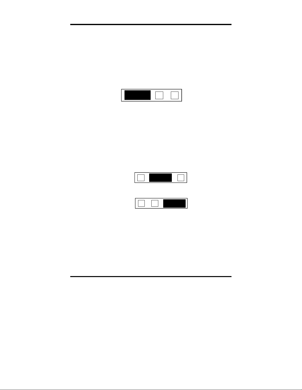
Clock Modes
The ULTRA COMM+422 employs a unique clocking option that allows the
end user to select from divide by 4, divide by 2 and divide by 1 clocking modes.
These modes are selected at Headers J1C through J4C.
To select the Baud rates commonly associated with COM: ports (i.e. 2400,
4800, 9600, 19.2, … 115.2K Bps ) place the jumper in the divide by 4 mode
(silk-screen DIV4).
DIV1
DIV2
DIV4
Figure 12 - Clocking Mode 'Divide By 4’
To double these rates up to a maximum rate for 230.4K bps place the jumper in
the divide by 2 (silk-screen DIV2) position.
DIV1
DIV2
DIV4
Figure 13 - Clocking Mode 'Divide By 2’
To select the maximum data rate (460.8K bps) place the jumper in the divide by
1 (silk-screen DIV1) position.
DIV1
DIV2
DIV4
Figure 14 - Clocking Mode 'Divide By 1’
Sealevel Systems ULTRA COMM+422 Page 10
Page 14

Card Setup
Baud Rates and Divisors for the ‘Div1’ mode
The following table shows some common data rates and the rates you should
choose to match them if using the adapter in the ‘Div1’ mode.
For this Data Rate Choose this Data Rate
1200 bps 300 bps
2400 bps 600 bps
4800 bps 1200 bps
9600 bps 2400 bps
19.2K bps 4800 bps
57.6 K bps 14.4K bps
115.2 K bps 28.8K bps
230.4K bps 57.6 K bps
460.8K bps 115.2 K bps
If your communications package allows the use of Baud rate divisors, choose the
appropriate divisor from the following table:
For this Data Rate Choose this Divisor
1200 bps 384
2400 bps 192
4800 bps 96
9600 bps 48
19.2K bps 24
38.4K bps 12
57.6K bps 8
115.2K bps 4
230.4K bps 2
460.8K bps 1
Sealevel Systems ULTRA COMM+422 Page 11
Page 15

Card Setup
Baud Rates and Divisors for the ‘Div2’ mode
The following table shows some common data rates and the rates you should
choose to match them if using the adapter in the ‘Div2’ mode.
For this Data Rate Choose this Data Rate
1200 bps 600 bps
2400 bps 1200 bps
4800 bps 2400bps
9600 bps 4800 bps
19.2K bps 9600 bps
38.4K bps 19.2K bps
57.6 K bps 28.8K bps
115.2 K bps 57.6 K bps
230.4 K bps 115.2 K bps
If your communications package allows the use of Baud rate divisors, choose the
appropriate divisor from the following table:
For this Data Rate Choose this Divisor
1200 bps 192
2400 bps 96
4800 bps 48
9600 bps 24
19.2K bps 12
38.4K bps 8
57.6K bps 4
115.2K bps 2
230.4K bps 1
Sealevel Systems ULTRA COMM+422 Page 12
Page 16

Installation
Installation
The ULTRA COMM+422 can be installed in any of the PC expansion slots.
The ULTRA COMM+422 contains several jumper straps for each port that
must be set for proper operation.
1. Turn off PC power. Disconnect the power cord.
2. Remove the PC case cover.
3. Locate an available slot and remove the blank metal slot cover.
4. Gently insert the ULTRA COMM+422 into the slot. Make sure that the
adapter is seated properly.
5. Replace the screw.
6. Install the “Spider” Cable
7. Replace the cover.
8. Connect the power cord.
Installation is complete.
Operating System Installation
For Windows Users
Start by choosing Install Software at the beginning of the CD. Choose
Asynchronous COM: Port Software, SeaCOM.
Other Operating Systems
Refer to the appropriate section of the Serial Utilities Software.
Sealevel Systems ULTRA COMM+422 Page 13
Page 17

Technical Description
Technical Description
The ULTRA COMM+422 utilizes the 16550 UART. This chip features
programmable baud rates, data format, interrupt control and a 16-byte input and
output FIFO. Also available as options are the Startech 16C650 and the Texas
Instruments 16C750 UARTs, that provide deeper FIFOs (32 bytes) and
enhanced clocking features.
A second version of the ULTRA COMM+422, p/n 3441 is available without
the auto enable feature for a reduced price. If point to point RS-422 or RTS
enabled RS-485 operations are desired, this option should be considered.
Features
• Automatic RS-485 driver enable/disable allows card to appear to be RS-232
requiring no additional drivers
• ‘PAL’ option allows for unique OEM address selection
• ‘Shareable’ IRQs allow more than one port to share a single IRQ
• IRQs 2/9-7, 10, 11, 12, 15 supported
• 16550 buffered UARTs standard, 16650 and 16750 UARTS available
• 16 Bit address decode allows for easier integration
• Speeds up to 460.8 K bps available
• Multiple clocking modes insuring compatibility with existing software
products
Modem Control Signal Considerations
Some software packages require the use of the modem handshake signals such as
RTS or CTS. Refer to your application software manual to determine the
requirements for modem control signals. If no requirements are mentioned, a
safe configuration is to tie RTS to CTS. This configuration will typically satisfy
the modem control signal requirements for most communications software.
Sealevel Systems ULTRA COMM+422 Page 14
Page 18

Technical Description
Interrupts
A good description of an interrupt and it’s importance to the IBM PC can be
found in the book ‘Peter Norton’s Inside the PC, Premier Edition’:
“ One of the key things that makes a computer different from any other kind of
man-made machine is that computers have the capability to respond to the
unpredictable variety of work that comes to them. The key to this capability is a
feature known as interrupts. The interrupt feature enables the computer to
suspend whatever it is doing and switch to something else in response to an
interruption, such as the press of a key on the keyboard.”
A good analogy of a PC interrupt would be the phone ringing. The phone ‘bell’
is a request for us to stop what we are currently doing and take up another task
(speak to the person on the other end of the line). This is the same process the
PC uses to alert the CPU that a task must be preformed. The CPU upon receiving
an interrupt makes a record of what the processor was doing at the time and
stores this information on the ‘stack’; this allows the processor to resume its
predefined duties after the interrupt is handled, exactly where it left off. Every
main sub-system in the PC has it’s own interrupt, frequently called an IRQ (short
for Interrupt ReQuest)..
In these early days of PC’s Sealevel Systems decided that the ability to share
IRQs was an important feature for any add-in I/O card. Consider that in the IBM
XT the available IRQs were IRQ0 through IRQ7. Of these interrupts only IRQ25 and IRQ7 were actually available for use. This made the IRQ a very valuable
system resource. To make the maximum use of these system resources Sealevel
Systems devised an IRQ sharing circuit that allowed more than one port to use a
selected IRQ. This worked fine as a hardware solution but presented the software
designer with a challenge to identify the source of the interrupt. The software
designer frequently used a technique referred to as ‘round robin polling’. This
method required the interrupt service routine to ‘poll’ or interrogate each UART
as to it’s interrupt pending status. This method of polling was sufficient for use
with slower speed communications, but as modems increased their through put
abilities this method of servicing shared IRQs became inefficient.
Sealevel Systems ULTRA COMM+422 Page 15
Page 19

Technical Description
Why use an ISP?
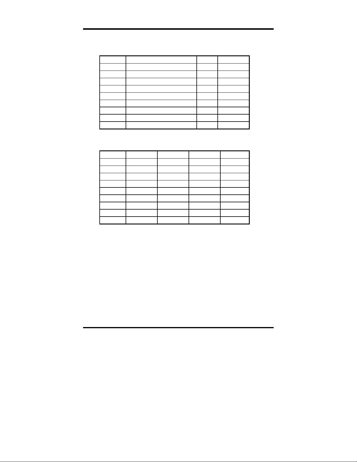
The answer to the polling inefficiency was the Interrupt Status Port (ISP). The
ISP is a read only 8-bit register that sets a corresponding bit when an interrupt is
pending. Port 1 interrupt line corresponds with Bit D0 of the status port, Port 2
with D1 etc. The use of this port means that the software designer now only has
to poll a single port to determine if an interrupt is pending.
The ISP is at Base+7 on each port (Example: Base = 280 Hex, Status Port = 287,
28F… etc.). The ULTRA COMM+422 will allow any one of the available
locations to be read to obtain the value in the status register. All four status ports
on the ULTRA COMM+422 are identical, so any one of the four can be read.
Example: This indicates that Channel 2 has an interrupt pending.
Bit Position: 7 6 5 4 3 2 1 0
Value Read: 0 0 0 0 0 0
0
1
Sealevel Systems ULTRA COMM+422 Page 16
Page 20
Technical Description
Connector Pin Assignments
DB-9 Pin Assignments
Signal Name Pin # Mode
GND Ground 5
TX + Transmit Data Positive 4 Output
TX- Transmit Data Negative 3 Output
RTS+ Request To Send Positive 6 Output
RTS- Request To Send Negative 7 Output
RX+ Receive Data Positive 1 Input
RX- Receive Data Negative 2 Input
CTS+ Clear To Send Positive 9 Input
CTS- Clear To Send Negative 8 Input
DB-37 Connector Pin Assignments
Port # 1 2 3 4
GND 33 14 24 5
TX- 35 12 26 3
RTS- 17 30 8 21
TX+ 34 13 25 4
RX- 36 11 27 2
CTS- 16 31 7 22
RTS+ 18 29 9 20
RX+ 37 10 28 1
CTS+ 15 32 6 23
Sealevel Systems ULTRA COMM+422 Page 17
Page 21

Specifications
Specifications
Environmental Specifications
Specification Operating Storage
Temperature
Range
Humidity Range
0º to 50º C
(32º to 122º F)
10 to 90% R.H.
Non-Condensing
Manufacturing
• IPC 610-A Class-III standards are adhered to with a 0.1 visual A.Q.L. and
100% Functional Testing.
• All Sealevel Systems Printed Circuit boards are built to U.L. 94V0 rating
and are 100% electrically tested. These printed circuit boards are solder
mask over bare copper or solder mask over tin nickel.
Power Consumption
-20º to 70º C
(-4º to 158º F)
10 to 90% R.H.
Non-Condensing
Supply line
3440 Rating
3441 Rating
+5 VDC
600 mA
570 mA
Mean Time Between Failures (MTBF)
Greater than 150,000 hours. (Calculated)
Physical Dimensions
Board length 8.0 inches (20.32 cm)
Board Height including Goldfingers 4.2 inches (10.66 cm)
Board Height excluding Goldfingers 3.9 inches (9.91 cm)
Sealevel Systems ULTRA COMM+422 Page 18
Page 22

Appendix A - Troubleshooting
Appendix A - Troubleshooting
A Serial Utility Diskette is supplied with the Sealevel Systems adapter and will
be used in the troubleshooting procedures. By using this diskette and following
these simple steps, most common problems can be eliminated without the need
to call Technical Support.
1. Identify all I/O adapters currently installed in your system. This includes
your on-board serial ports, controller cards, sound cards etc. The I/O
addresses used by these adapters, as well as the IRQ (if any) should be
identified.
2. Configure your Sealevel Systems adapter so that there is no conflict with
currently installed adapters. No two adapters can occupy the same I/O
address.
3. Make sure the Sealevel Systems adapter is using a unique IRQ. While the
Sealevel Systems adapter does allow the sharing of IRQs, many other
adapters (i.e. SCSI adapters & on-board serial ports) do not
typically selected via an on-board header block. Refer to the section on Card
Setup for help in choosing an I/O address and IRQ.
4. Make sure the Sealevel Systems adapter is securely installed in a
motherboard slot.
. The IRQ is
5. When running DOS or Windows 3.x refer to the Serial Utilities disk 1 and
the User Manual to verify that the Sealevel Systems adapter is configured
correctly. The supplied diskette contains a diagnostic program ‘SSD’ that
will verify if an adapter is configured properly. This diagnostic program is
written with the user in mind and is easy to use. Refer to the ‘README’ file
on the supplied diskette for detailed instructions on using ‘SSD’.
6. For Windows 95 and Windows NT, the diagnostic tool ‘WinSSD’ is
installed in the Sealevel folder on the Start Menu during the setup process.
First find the ports using the Device Manager, then use ‘WinSSD’ to verify
that the ports are functional.
7. Always use the Sealevel Systems diagnostic software when troubleshooting
a problem. This will eliminate any software issues from the equation.
Sealevel Systems ULTRA COMM+422 Page 19
Page 23

Appendix A - Troubleshooting
8. The following are known I/O conflicts:
• The 278 and 378 settings may conflict with your printer I/O
adapter.
• 3B0 cannot be used if a Monochrome adapter is installed.
• 3F8-3FF is typically reserved for COM1:
• 2F8-2FF is typically reserved for COM2:
• 3E8-3EF is typically reserved for COM3:
• 2E8-2EF is typically reserved for COM4:
9. Please refer to your included diskette for any post production manual
updates and application specific information.
10. Always use the Sealevel Systems diagnostic software when Troubleshooting
a problem. This will eliminate the software issue from the equation.
Sealevel Systems ULTRA COMM+422 Page 20
Page 24

Appendix B – How To Get Assistance
Appendix B - How To Get Assistance
Please refer to Troubleshooting Guide prior to calling Technical Support.
1. Begin by reading through the Trouble Shooting Guide in Appendix
A. If assistance is still needed please see below.
2. When calling for technical assistance, please have your user
manual and current adapter settings. If possible, please have the
adapter installed in a computer ready to run diagnostics.
3. Sealevel Systems provides an FAQ section on its web site. Please
refer to this to answer many common questions. This section can be
found at http://www.sealevel.com/faq.htm
4. Sealevel Systems maintains a Home page on the Internet. Our
home page address is www.sealevel.com
updates, and newest manuals are available via our FTP site that can
be accessed from our home page.
5. Technical support is available Monday to Friday from 8:00 a.m. to
5:00 p.m. eastern time. Technical support can be reached at (864)
843-4343.
.
. The latest software
RETURN AUTHORIZATION MUST BE OBTAINED FROM SEALEVEL
SYSTEMS BEFORE RETURNED MERCHANDISE WILL BE
ACCEPTED. AUTHORIZATION CAN BE OBTAINED BY CALLING
SEALEVEL SYSTEMS AND REQUESTING A RETURN
MERCHANDISE AUTHORIZATION (RMA) NUMBER.
Sealevel Systems ULTRA COMM+422 Page 21
Page 25

Appendix C - Electrical Interface
Appendix C - Electrical Interface
RS-422
The RS-422 specification defines the electrical characteristics of balanced
voltage digital interface circuits. RS-422 is a differential interface that defines
voltage levels and driver/receiver electrical specifications. On a differential
interface, logic levels are defined by the difference in voltage between a pair of
outputs or inputs. In contrast, a single ended interface, for example RS-232,
defines the logic levels as the difference in voltage between a single signal and a
common ground connection. Differential interfaces are typically more immune to
noise or voltage spikes that may occur on the communication lines. Differential
interfaces also have greater drive capabilities that allow for longer cable lengths.
RS-422 is rated up to 10 Megabits per second and can have cabling 4000 feet
long. RS-422 also defines driver and receiver electrical characteristics that will
allow 1 driver and up to 32 receivers on the line at once. RS-422 signal levels
range from 0 to +5 volts. RS-422 does not define a physical connector.
RS-485
RS-485 is backwardly compatible with RS-422; however, it is optimized for
partyline or multi-drop applications. The output of the RS-422/485 driver is
capable of being Active (enabled) or Tri-State (disabled). This capability allows
multiple ports to be connected in a multi-drop bus and selectively polled.
RS-485 allows cable lengths up to 4000 feet and data rates up to 10 Megabits
per second. The signal levels for RS-485 are the same as those defined by
RS-422. RS-485 has electrical characteristics that allow for 32 drivers and 32
receivers to be connected to one line. This interface is ideal for multi-drop or
network environments. RS-485 tri-state driver (not dual-state) will allow the
electrical presence of the driver to be removed from the line. Only one driver
may be active at a time and the other driver(s) must be tri-stated. RS-485 can be
cabled in two ways, two wire and four wire mode. Two wire mode does not
allow for full duplex communication, and requires that data be transferred in
only one direction at a time. For half-duplex operation, the two transmit pins
should be connected to the two receive pins (Tx+ to Rx+ and Tx- to Rx-). Four
wire mode allows full duplex data transfers. RS-485 does not define a connector
pin-out or a set of modem control signals. RS-485 does not define a physical
connector.
Sealevel Systems ULTRA COMM+422 Page 22
Page 26
Appendix D - Asynchronous Communications
r
Appendix D - Asynchronous Communications
Serial data communications implies that individual bits of a character are
transmitted consecutively to a receiver that assembles the bits back into a
character. Data rate, error checking, handshaking, and character framing
(start/stop bits) are pre-defined and must correspond at both the transmitting and
receiving ends.
Asynchronous communications is the standard means of serial data
communication for PC compatibles and PS/2 computers. The original PC was
equipped with a communication or COM: port that was designed around an 8250
Universal Asynchronous Receiver Transmitter (UART). This device allows
asynchronous serial data to be transferred through a simple and straightforward
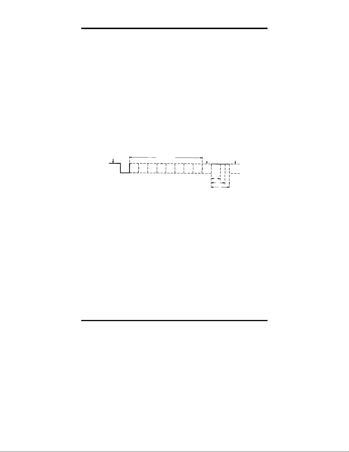
programming interface. Character boundaries for asynchronous communications
are defined by a starting bit followed by a pre-defined number of data bits (5, 6,
7, or 8). The end of the character is defined by the transmission of a pre-defined
number of stop bits (usual 1, 1.5 or 2). An extra bit used for error detection is
often appended before the stop bits.
Idle state of
line
1
0
5 to 8 Data Bits
Figure 15 - Asynchronous Communications Bit Diagram
Odd, Even
or
Unused
P
BIT
STOP
Remain Idle o
next start bit
1
1.5
2
This special bit is called the parity bit. Parity is a simple method of determining
if a data bit has been lost or corrupted during transmission. There are several
methods for implementing a parity check to guard against data corruption.
Common methods are called (E)ven Parity or (O)dd Parity. Sometimes parity is
not used to detect errors on the data stream. This is refereed to as (N)o parity.
Because each bit in asynchronous communications is sent consecutively, it is
easy to generalize asynchronous communications by stating that each character is
wrapped (framed) by pre-defined bits to mark the beginning and end of the serial
transmission of the character. The data rate and communication parameters for
asynchronous communications have to be the same at both the transmitting and
receiving ends. The communication parameters are baud rate, parity, number of
data bits per character, and stop bits (i.e. 9600,N,8,1).
Sealevel Systems ULTRA COMM+422 Page 23
Page 27

Appendix E - Silk-Screen
Appendix E - Silk-Screen
4.2"
8.0"
3.9"
Sealevel Systems ULTRA COMM+422 Page 24
Page 28

Appendix F - Compliance Notices
Appendix F - Compliance Notices
Federal Communications Commission Statement
FCC - This equipment has been tested and found to comply with the limits for
Class A digital device, pursuant to Part 15 of the FCC Rules. These limits are
designed to provide reasonable protection against harmful interference when the
equipment is operated in a commercial environment. This equipment generates,
uses, and can radiate radio frequency energy and, if not installed and used in
accordance with the instruction manual, may cause harmful interference to radio
communications. Operation of this equipment in a residential area is likely to
cause harmful interference in such case the user will be required to correct the
interference at his own expense.
EMC Directive Statement
Products bearing the CE Label fulfill the requirements of the
EMC directive (89/336/EEC) and of the low-voltage directive
(73/23/EEC) issued by the European Commission.
To obey these directives, the following European standards must be met:
• EN55022 Class A - “Limits and methods of measurement of radio
• EN55024-‘Information technology equipment Immunity
• EN60950 (IEC950) - “Safety of information technology
equipment, including electrical business equipment”
This is a Class A Product. In a domestic environment this product may
cause radio interference in which case the user may be required to take
adequate measures.
Always use cabling provided with this product if possible. If no cable is
provided or if an alternate cable is required, use high quality shielded cabling to
maintain compliance with FCC/EMC directives.
interference characteristics of information technology equipment”
characteristics Limits and methods of measurement.
Warning
Sealevel Systems ULTRA COMM+422 Page 25
Page 29

Warranty
Warranty
Sealevel Systems, Inc. provides a limited lifetime
warranty. Should this product fail to be in good
working order at any time during this period, Sealevel
Systems will, at it’s option, replace or repair it at no
additional charge except as set forth in the following
terms. This warranty does not apply to products damaged by misuse,
modifications, accident or disaster.
Sealevel Systems assumes no liability for any damages, lost profits, lost savings
or any other incidental or consequential damage resulting from the use, misuse
of, or inability to use this product. Sealevel Systems will not be liable for any
claim made by any other related party.
RETURN AUTHORIZATION MUST BE OBTAINED FROM SEALEVEL
SYSTEMS BEFORE RETURNED MERCHANDISE WILL BE
ACCEPTED. AUTHORIZATION CAN BE OBTAINED BY CALLING
SEALEVEL SYSTEMS AND REQUESTING A RETURN
MERCHANDISE AUTHORIZATION (RMA) NUMBER.
Sealevel Systems, Incorporated
2779 Greenville Highway
P.O. Box 830
Liberty, SC 29657 USA
(864) 843-4343 FAX:(864) 843-3067
www.sealevel.com
email: support@sealevel.com
Technical Support is available from 8 a.m. to 5 p.m. Eastern time.
Monday - Friday
Trademarks
Sealevel Systems, Incorporated acknowledges that all trademarks referenced in
this manual are the service mark, trademark, or registered trademark of the
respective company.
ULTRA COMM+422 is a trademark of Sealevel Systems, Incorporated.
Sealevel Systems ULTRA COMM+422 Page 26
 Loading...