

Page 1

VERSA COMM+4/EX™
USER MANUAL
Part #3405
Sealevel Systems, Inc. Telephone: (864) 843-4343
PO Box 830 Fax: (864) 843-3067
Liberty, SC 29657 USA www.sealevel.com
Page 2

Contents
INTRODUCTION ........................................................................ 1
OVERVIEW......................................................................................1
WHAT’S INCLUDED.........................................................................1
FACTORY DEFAULT SETTINGS ........................................................1
CARD SETUP ............................................................................ 2
ADDRESS SELECTION......................................................................2
JUMPER SELECTIONS ......................................................................4
IRQ Selection..............................................................................4
INTERRUPT MODES.........................................................................5
CLOCK MODES ...............................................................................6
BAUD RATES AND DIVISORS FOR THE ‘DIV1’ MODE .......................7
BAUD RATES AND DIVISORS FOR THE ‘DIV2’ MODE .......................8
INSTALLATION ......................................................................... 9
OPERATING SYSTEM INSTALLATION ...............................................9
For Windows Users.....................................................................9
Other Operating Systems ............................................................9
SYSTEM INSTALLATION ..................................................................9
TECHNICAL DESCRIPTION .................................................... 10
FEATURES.....................................................................................10
INTERRUPT STATUS PORT.............................................................10
CONNECTOR PIN ASSIGNMENTS....................................................11
DB-25 Male (RS-232 DTE)......................................................11
DB-9 Male (EIA-574 DTE)......................................................11
DB-37 Male ..............................................................................12
SPECIFICATIONS .................................................................... 13
ENVIRONMENTAL SPECIFICATIONS ...............................................13
MANUFACTURING.........................................................................13
POWER CONSUMPTION .................................................................13
MEAN TIME BETWEEN FAILURES (MTBF) ...................................13
PHYSICAL DIMENSIONS.................................................................13
PPENDIX A - TROUBLESHOOTING ...................................... 14
A
A
PPENDIX B - HOW TO GET ASSISTANCE............................ 16
APPENDIX C - ELECTRICAL INTERFACE .............................. 17
RS-232.........................................................................................17
PPENDIX D - ASYNCHRONOUS COMMUNICATIONS ............ 18
A
Page 3

APPENDIX E - SILK-SCREEN ................................................. 19
APPENDIX F - SCHEMATIC .................................................... 20
APPENDIX G - COMPLIANCE NOTICES ................................. 22
FEDERAL COMMUNICATIONS COMMISSION STATEMENT...............22
EMC DIRECTIVE STATEMENT ......................................................22
WARRANTY............................................................................ 23
Figures
Figure 1 - Available Address Combinations ............................................2
Figure 2 - Address Selection Table ...........................................................3
Figure 3 - Port to Connector Table ..........................................................3
Figure 4 – Headers J1B – J4B, IRQ Selection.........................................4
Figure 5 - Header J1A, Normal IRQ Mode .............................................5
Figure 6 - Header J1A & J2A, Shared IRQ Mode..................................5
Figure 7 - Clocking Mode ‘Divide By 4’...................................................6
Figure 8 - Clocking Mode ‘Divide By 2’...................................................6
Figure 9 - Clocking Mode ‘Divide By 1’...................................................6
Figure 10 - Asynchronous Communications Bit Diagram....................18
© Sealevel Systems, Inc.
SL9144 Revision 7/2006
Sealevel Systems, Incorporated. All rights reserved.
Page 4
Introduction
Introduction
Overview
The Sealevel Systems VERSA COMM+4/EX provides the PC with four
RS-232 asynchronous ports. The VERSA COMM+4/EX allows for connection
to any device utilizing the RS-232 electrical interface, such as modems,
data-entry terminals, and plotters.
What’s Included
The VERSA COMM+4/EX is shipped with the following items. If any of these
items is missing or damaged, contact the supplier.
• VERSA COMM+4/EX Serial I/O Adapter
• DB-37 to four DB-25 ‘Spider Cable’ (DB-9 Spider Cable is
available)
• Sealevel Software
Factory Default Settings
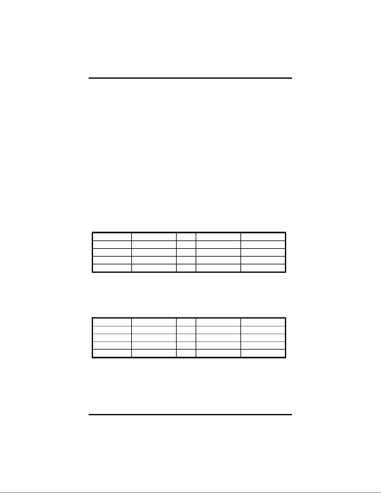
The VERSA COMM+4/EX factory default settings are as follows:
Port # Base Address IRQ IRQ Mode Clock Divisor
Port 1 280 5 M 4
Port 2 288 5 S 4
Port 3 290 5 S 4
Port 4 298 5 S 4
To install the VERSA COMM+4/EX using factory default settings, refer to
Installation on page 9.
For your reference, record installed VERSA COMM+4/EX settings below:
Port # Base Address IRQ IRQ Mode Clock Divisor
Port 1
Port 2
Port 3
Port 4
Sealevel Systems VERSA COMM+4/EX Page 1
Page 5
Card Setup
Card Setup
The VERSA COMM+4/EX contains several jumper straps that must be set for
proper operation.
Address Selection
Each port on the VERSA COMM+4/EX occupies eight consecutive I/O
locations. A DIP-switch is used to set the base address for these locations.
The VERSA COMM+4/EX has a unique addressing scheme that allows it to be
completely compatible with Sealevel Systems’ older four port RS-232 interface
adapters (p/n 3064, 3065, 3066 and 3400) and provides the ability to select
specific non-linear address combinations (i.e. 3F8, 2F8, 3E8, 2E8).
The first addressing scheme allows the user to select the addresses for its ports
from a table of available address combinations.
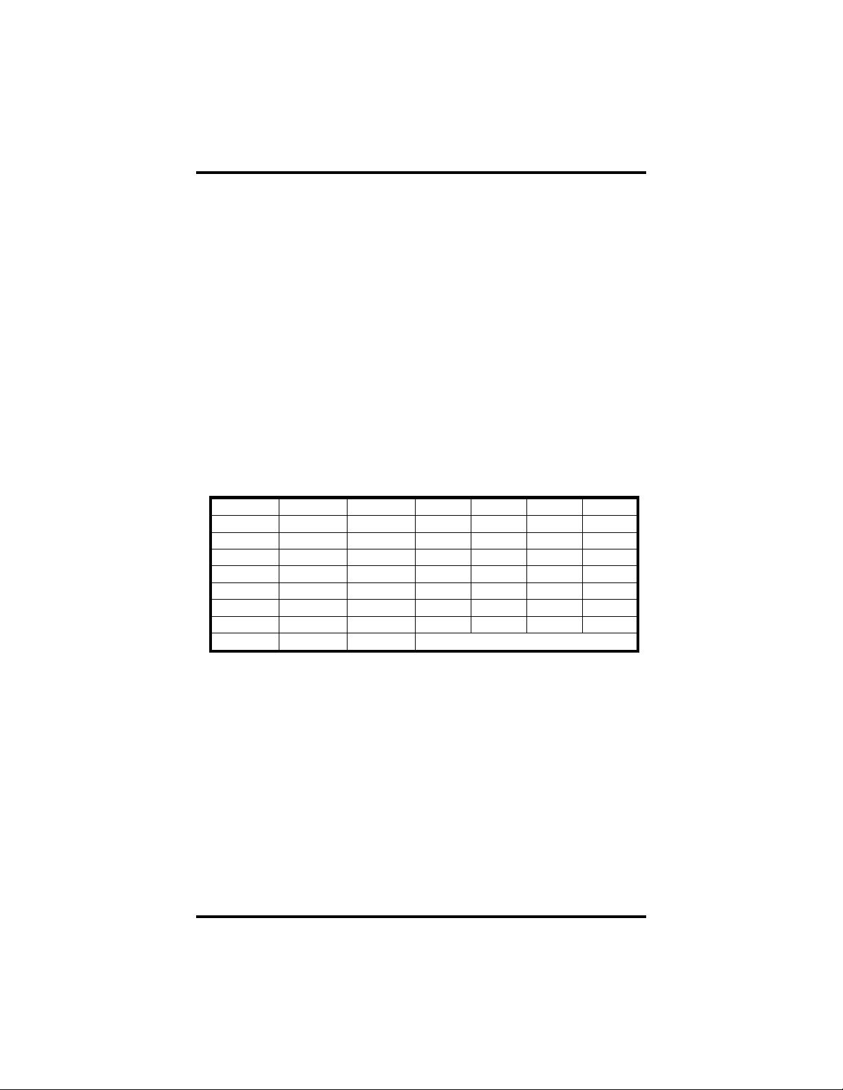
The following table shows the addressing combinations available. If different
address combinations are required, please contact Sealevel Systems Technical
Support about custom PAL options.
Switch 6 Switch 7 Switch 8 Port 1 Port 2 Port 3 Port 4
On On Off 3F8 2F8 3E8 2E8
On Off On 2F8 3E8 2E8 2E0
On Off Off 3E8 2E8 280 288
Off On On 500 508 510 518
Off On Off 580 588 590 598
Off Off On 1500 1508 1510 1518
Off Off Off 3220 3228 4220 4228
On On On Addresses set up by switches 1 - 5
Figure 1 - Available Address Combinations
Note: Each COM: port in the system should have a unique address. Typically
COM1: - COM4: addresses are 3F8, 2F8, 3E8 and 2E8 Hex.
Refer to Appendix A for common address contentions.
Sealevel Systems VERSA COMM+4/EX Page 2
Page 6
Card Setup
The second mode of address selection provides the compatibility mode. In this
mode the DIP-switch sets the base address and the adapter occupies 32
consecutive I/O locations. The following table illustrates the location of each
port and its relationship to the other ports.
Note: For switches 1 - 5 to become active, switches 6, 7 & 8 must be set in
the ‘On’ or ‘Up’ position.
Switch Settings
Address lines Æ A9 A8 A7 A6 A5
Address Selected 1 2 3 4 5
280-29F Off On Off On On
2A0-2BF Off On Off On Off
380-39F Off Off Off On On
1A0-1BF On Off Off On Off
2E0-2FF Off On Off Off Off
Figure 2 - Address Selection Table
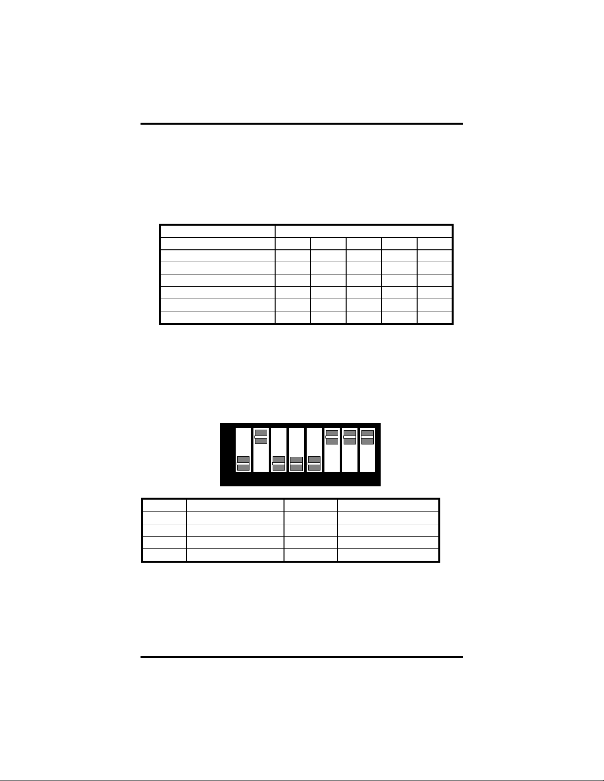
The following illustration shows the correlation between the DIP-switch setting
and the address bits used to determine the base address. In the example below,
address 2E0 is selected as a base. Address 2E0 in binary is XX 10 111X XXXX
where X = a non-selectable address bit.
A9 A5
ON
OFF
1 2 3 4 5 6 7 8
Port # Connector Location Address Example (Base=2E0)
1
2
3
4
Sealevel Systems VERSA COMM+4/EX Page 3
1 Base+0 2E0-2E7
2 Base+8 2E8-2EF
3 Base+16 2F0-2F7
4 Base+24 2F8-2FF
Figure 3 - Port to Connector Table
Page 7
Card Setup
Jumper Selections
For ease of configuration, the headers are grouped by port. Port one headers
have a ‘J1’ prefix, Port two headers have the ‘J2’ prefix, etc. For example, the
header that controls the Port one IRQ selection is J1B, the header that controls
the Port 2 IRQ selection is J2B. The silk-screen also provides information for
configuring the adapter without the use of the manual. This is particularly useful
in field re-configuration.
IRQ Selection
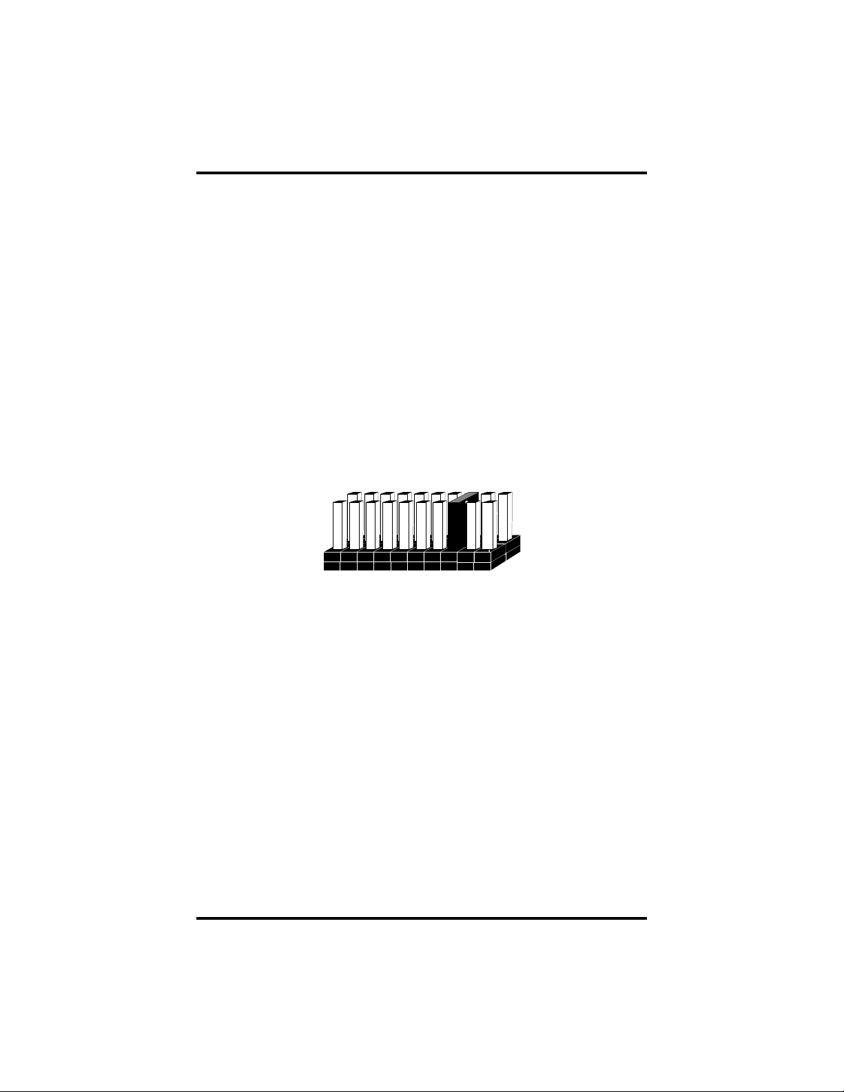
Headers J1B through J4B select the interrupt request for each serial port. If
COM1: is selected, the corresponding jumper must be on the IRQ4 setting. If
COM2: is selected, the corresponding jumper must be on IRQ3. (This only
applies to the traditional DOS COM: port assignments, in Windows COM1: can
use I/O address 300 and IRQ15 if it is available!)
34567 101112159
Figure 4 – Headers J1B – J4B, IRQ Selection
Note: Most DOS communications software applications default COM3: to IRQ4
and COM4: to IRQ3. This requires the sharing of interrupts between
COM1: and COM3:, and between COM2: and COM4:. While this is the
default, it is not always the preferred setting. Check your software
configuration instructions to determine the most appropriate IRQ
selection.
Any two or more ports can share a common IRQ by placing the jumpers on the
same IRQ setting and setting the appropriate selections at J1A through J4A.
When sharing IRQs, many operating systems (i.e. Windows NT) will require the
location of the Interrupt Status Port (ISP). Please see Page 10 for a description
of the ISP and how it is used.
Sealevel Systems VERSA COMM+4/EX Page 4
Page 8
Card Setup
Interrupt Modes
Headers J1A through J4A select the interrupt modes for each port. Each port
must be set in the correct mode to insure proper operation.
‘N’ indicates the (N)ormal, single interrupt per port mode. ‘S’ Indicates the
(S)hared interrupt mode, which allows more than one port to access a single
IRQ. ‘M’ indicates the inclusion of a 1K ohm pull-down resistor required on one
port when sharing interrupts.
J1A
NM
Figure 5 - Header J1A, Normal IRQ Mode
Set the jumpers to ‘S’ for shared interrupt mode on all blocks sharing an IRQ
except one. Set that port block for ‘M’. This provides the pull-down resistor
circuit that makes sharing IRQs possible. If you are using more than one
VERSA COMM+4/EX or a compatible adapter in a bus you should only have
one port set to ‘M’. The following example shows two ports sharing a single
IRQ.
S
J1A
NSM
J2A
NSM
Figure 6 - Header J1A & J2A, Shared IRQ Mode
Set the jumper to ‘S’ if you are using more than one VERSA COMM+4/EX in
a bus or to completely remove the pull-down resistor for hardware compatibility.
Setting the adapter in this configuration when it is not accompanied by a
pull-down resistor will prevent the ports from triggering an interrupt.
Sealevel Systems VERSA COMM+4/EX Page 5
Page 9

Card Setup
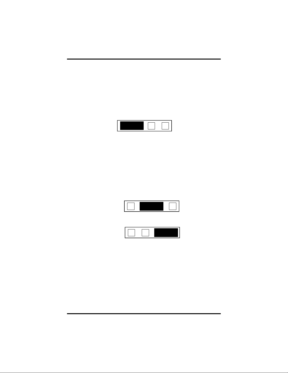
Clock Modes
The VERSA COMM+4/EX employs a unique clocking option that allows the
end user to select from divide by 4, divide by 2 and divide by 1 clocking modes.
This mode is selected at J5.
To select the Baud rates commonly associated with COM: ports (i.e. 2400,
4800, 9600, 19.2, … 115.2K Bps) place the jumper in the divide by 4 mode
(silk-screen DIV4).
DIV1
DIV2
DIV4
Figure 7 - Clocking Mode ‘Divide By 4’
To double these rates up to a maximum rate for 230.4K bps place the jumper in
the divide by 2 (silk-screen DIV2) position.
DIV1
DIV2
DIV4
Figure 8 - Clocking Mode ‘Divide By 2’
To select the maximum data rate (460.8K bps) place the jumper in the divide by
1 (silk-screen DIV1) position.
DIV1
DIV2
DIV4
Figure 9 - Clocking Mode ‘Divide By 1’
Sealevel Systems VERSA COMM+4/EX Page 6
Page 10

Card Setup
Baud Rates and Divisors for the ‘Div1’ mode
The following table shows some common data rates and the rates you should
choose to match them if using the adapter in the ‘Div1’ mode.
For this Data Rate Choose this Data Rate
1200 bps 300 bps
2400 bps 600 bps
4800 bps 1200 bps
9600 bps 2400 bps
19.2K bps 4800 bps
57.6 K bps 9600 bps
115.2 K bps 19.2K bps
230.4K bps 57.6 K bps
460.8K bps 115.2 K bps
If your communications package allows the use of Baud rate divisors, choose the
appropriate divisor from the following table:
For this Data Rate Choose this Divisor
1200 bps 384
2400 bps 192
4800 bps 96
9600 bps 48
19.2K bps 24
38.4K bps 12
57.6K bps 8
115.2K bps 4
230.4K bps 2
460.8K bps 1
Sealevel Systems VERSA COMM+4/EX Page 7
Page 11

Card Setup
Baud Rates and Divisors for the ‘Div2’ mode
The following table shows some common data rates and the rates you should
choose to match them if using the adapter in the ‘Div2’ mode.
For this Data Rate Choose this Data Rate
1200 bps 600 bps
2400 bps 1200 bps
4800 bps 2400bps
9600 bps 4800 bps
19.2K bps 9600 bps
38.4K bps 19.2K bps
57.6 K bps 38.4K bps
115.2 K bps 57.6 K bps
230.4 K bps 115.2 K bps
If your communications package allows the use of Baud rate divisors, choose the
appropriate divisor from the following table:
For this Data Rate Choose this Divisor
1200 bps 192
2400 bps 96
4800 bps 48
9600 bps 24
19.2K bps 12
38.4K bps 8
57.6K bps 4
115.2K bps 2
230.4K bps 1
Sealevel Systems VERSA COMM+4/EX Page 8
Page 12

Installation
Installation
Operating System Installation
For Windows Users
Start by choosing Install Software at the beginning of the CD. Choose
Asynchronous COM: Port Software, SeaCOM.
Other Operating Systems
Refer to the appropriate section of the Serial Utilities Software.
System Installation
The VERSA COMM+4/EX can be installed in any of the PC ISA expansion
slots. The VERSA COMM+4/EX contains several jumper straps for each port
that must be set for proper operation.
1. Turn off PC power. Disconnect the power cord.
2. Remove the PC case cover.
3. Locate an available slot and remove the blank metal slot cover.
4. Gently insert the VERSA COMM+4/EX into the slot. Make sure that the
adapter is seated properly.
5. Replace the screw.
6. Replace the cover.
7. Install the “Spider Cable”.
8. Connect the power cord.
Installation is complete.
Sealevel Systems VERSA COMM+4/EX Page 9
Page 13

Technical Description
Technical Description
The VERSA COMM+4/EX utilizes the 16C554 UART. This chip features
programmable baud rate, data format, interrupt control and a 16-byte input and
output FIFO, and is functionally 4 16C550 UARTs. A full array of advanced
UARTs is also available for this card. Contact Sealevel Systems, Inc. for more
information.
Features
• ‘Shareable’ IRQs allow more than one port to share a single IRQ with
appropriate software drivers
• IRQs 3-7, 9-12, 15 supported
• 16C554 buffered Quad UART Standard
• 16 Bit address decode allows for easier integration
• Speeds up to 460.8 K bps
• Multiple clocking modes insuring compatibility with existing software
products
Interrupt Status Port
The VERSA COMM+4/EX provides the user with an Interrupt Status Port
(ISP) for greater throughput when servicing multiple ports on a single interrupt
line. The ISP is a read only 8-bit register that sets a corresponding bit when an
interrupt is pending. Port 1 interrupt line corresponds with Bit D0 of the status
port, Port 2 with D1 etc.
The ISP is located at Base+7 on each port (Example: Base = 280 Hex, Status
Port = 287, 28F… etc.). This allows any one of eight locations to be read to
obtain the value in the status register. All four status ports on the
VERSA COMM+4/EX are identical, so any one of the four can be read to
determine which interrupt is pending. In the following example Channel 2 has an
interrupt pending. D4 through D7 are not driven into the interrupt status register
and can be 1’s or 0’s.
Bit Position: 7 6 5 4 3 2 1 0
Value Read: 0 0 0 0 0 0
Sealevel Systems VERSA COMM+4/EX Page 10
0
1
Page 14

Technical Description
Connector Pin Assignments
DB-25 Male (RS-232 DTE)
Signal Name Pin # Mode
GND Ground 7
TD Transmit Data 2 Output
RTS Request To Send 4 Output
DTR Data Terminal Ready 20 Output
RD Receive Data 3 Input
CTS Clear To Send 5 Input
DSR Data Set Ready 6 Input
DCD Data Carrier Detect 8 Input
RI Ring Indicator 22 Input
DB-9 Male (EIA-574 DTE)
Signal Name Pin # Mode
GND Ground 5
TD Transmit Data 3 Output
RTS Request To Send 7 Output
DTR Data Terminal Ready 4 Output
RD Receive Data 2 Input
CTS Clear To Send 8 Input
DSR Data Set Ready 6 Input
DCD Data Carrier Detect 1 Input
RI Ring Indicator 9 Input
Sealevel Systems VERSA COMM+4/EX Page 11
Page 15

Technical Description
DB-37 Male
Port # 1 2 3 4
GND 33 14 24 5
TD 35 12 26 3
RTS 17 30 8 21
DTR 34 13 25 4
RD 36 11 27 2
CTS 16 31 7 22
DSR 18 29 9 20
DCD 37 10 28 1
RI 15 32 6 23
Technical Note: Please terminate any control signals that are not going to be
used. The most common way to do this is connect RTS to CTS and RI. Also,
connect DCD to DTR and DSR. Terminating these pins, if not used, will help
insure you get the best performance from your adapter.
Sealevel Systems VERSA COMM+4/EX Page 12
Page 16

Specifications
Specifications
Environmental Specifications
Specification Operating Storage
Temperature
Range
Humidity Range
0º to 50º C
(32º to 122º F)
10 to 90% R.H.
Non-Condensing
Manufacturing
• All Sealevel Systems Printed Circuit boards are built to U.L. 94V0 rating
and are 100% electrically tested. These printed circuit boards are solder
mask over bare copper or solder mask over tin nickel.
Power Consumption
-20º to 70º C
(-4º to 158º F)
10 to 90% R.H.
Non-Condensing
Supply line
Rating
+12 VDC -12 VDC +5 VDC
60 mA 80 mA 210 mA
Mean Time Between Failures (MTBF)
Greater than 150,000 hours. (Calculated)
Physical Dimensions
Board length 5.2 inches (13.208 cm.)
Board Height including Goldfingers 3.4 inches (8.636 cm.)
Board Height excluding Goldfingers 3.1 inches (7.874 cm.)
Sealevel Systems VERSA COMM+4/EX Page 13
Page 17

Appendix A - Troubleshooting
Appendix A - Troubleshooting
Serial Utility test software is supplied with the Sealevel Systems adapter and will
be used in the troubleshooting procedures. By using this software and following
these simple steps, most common problems can be eliminated without the need
to call Technical Support.
1. Identify all I/O adapters currently installed in your system. This includes
your on-board serial ports, controller cards, sound cards etc. The I/O
addresses used by these adapters, as well as the IRQ (if any) should be
identified.
2. Configure your Sealevel Systems adapter so that there is no conflict with
currently installed adapters. No two adapters can occupy the same I/O
address.
3. Make sure the Sealevel Systems adapter is using a unique IRQ The IRQ is
typically selected via an on-board header block. Refer to the section on Card
Setup for help in choosing an I/O address and IRQ.
4. Make sure the Sealevel Systems adapter is securely installed in a
motherboard slot.
5. When running DOS, Windows 3.x or other operating systems refer to the
Serial Utilities software for that operating system and the User Manual to
verify that the Sealevel Systems adapter is configured correctly. The
supplied software contains a diagnostic program 'SSD' that runs under DOS
and will verify if an adapter is configured properly. This diagnostic program
is written with the user in mind and is easy to use. Refer to the DIAG.txt file
in the dos\diag directory for detailed instructions on using 'SSD'.
6. For Windows 95/98 and Windows NT, the diagnostic tool 'WinSSD' is
installed in the Sealevel folder on the Start Menu during the setup process.
First find the ports using the Device Manager, then use 'WinSSD' to verify
that the ports are functional.
7. Always use the Sealevel Systems diagnostic software when troubleshooting
a problem. This will help eliminate any software issues and identify any
hardware conflicts.
Sealevel Systems VERSA COMM+4/EX Page 14
Page 18

Appendix A - Troubleshooting
8. The following are known I/O conflicts:
• The 278 and 378 settings may conflict with your printer I/O adapter.
• 3B0 cannot be used if a Monochrome adapter is installed.
• 3F8-3FF is typically reserved for COM1:
• 2F8-2FF is typically reserved for COM2:
• 3E8-3EF is typically reserved for COM3:
• 2E8-2EF is typically reserved for COM4:
Sealevel Systems VERSA COMM+4/EX Page 15
Page 19

Appendix B - How To Get Assistance
Appendix B - How To Get Assistance
Please refer to Troubleshooting Guide prior to calling Technical Support.
1. Begin by reading through the Trouble Shooting Guide in Appendix
A. If assistance is still needed please see below.
2. When calling for technical assistance, please have your user
manual and current adapter settings. If possible, please have the
adapter installed in a computer ready to run diagnostics.
3. Sealevel Systems provides an FAQ section on its web site. Please
refer to this to answer many common questions. This section can be
found at http://www.sealevel.com/faq.htm
4. Sealevel Systems maintains a Home page on the Internet. Our
home page address is www.sealevel.com
updates, and newest manuals are available via our FTP site that can
be accessed from our home page.
5. Technical support is available Monday to Friday from 8:00 a.m. to
5:00 p.m. eastern time. Technical support can be reached at (864)
843-4343.
.
. The latest software
RETURN AUTHORIZATION MUST BE OBTAINED FROM SEALEVEL
SYSTEMS BEFORE RETURNED MERCHANDISE WILL BE
ACCEPTED. AUTHORIZATION CAN BE OBTAINED BY CALLING
SEALEVEL SYSTEMS AND REQUESTING A RETURN
MERCHANDISE AUTHORIZATION (RMA) NUMBER.
Sealevel Systems VERSA COMM+4/EX Page 16
Page 20

Appendix C - Electrical Interface
Appendix C - Electrical Interface
RS-232
Quite possibly the most widely used communication standard is RS-232. This
implementation has been defined and revised several times and is often referred
to as RS-232-C/D/E or EIA/TIA-232-C/D/E. It is defined as “Interface between
Data Terminal Equipment and Data Circuit- Terminating Equipment Employing
Serial Binary Data Interchange”. The mechanical implementation of RS-232 is
on a 25-pin D sub connector. The IBM PC computer defined the RS-232 port on
a 9 pin D sub connector and subsequently the EIA/TIA approved this
implementation as the EIA/TIA-574 standard. This standard has defined as the
“9-Position Non-Synchronous Interface between Data Terminal Equipment and
Data Circuit-Terminating Equipment Employing Serial Binary Data
Interchange”. Both implementations are in wide spread use and will be referred
to as RS-232 in this document. RS-232 is capable of operating at data rates up to
20K bps / 50 ft. The absolute maximum data rate may vary due to line conditions
and cable lengths. RS-232 often operates at 38.4K bps over very short distances.
The voltage levels defined by RS-232 range from -12 to +12 volts. RS-232 is a
single ended or unbalanced interface, meaning that a single electrical signal is
compared to a common signal (ground) to determine binary logic states. A
voltage of +12 volts (usually +3 to +10 volts) represents a binary 0 (space) and 12 volts (-3 to -10 volts) denote a binary 1 (mark). The RS-232 and the
EIA/TIA-574 specification define two types of interface circuits Data Terminal
Equipment (DTE) and Data Circuit-Terminating Equipment (DCE). The
Sealevel Systems Adapter is a DTE interface.
Sealevel Systems VERSA COMM+4/EX Page 17
Page 21

Appendix D - Asynchronous Communications
r
Appendix D - Asynchronous Communications
Serial data communications implies that individual bits of a character are
transmitted consecutively to a receiver that assembles the bits back into a
character. Data rate, error checking, handshaking, and character framing
(start/stop bits) are pre-defined and must correspond at both the transmitting and
receiving ends.
Asynchronous communications is the standard means of serial data
communication for PC compatibles and PS/2 computers. The original PC was
equipped with a communication or COM: port that was designed around an 8250
Universal Asynchronous Receiver Transmitter (UART). This device allows
asynchronous serial data to be transferred through a simple and straightforward
programming interface. A starting bit followed by a pre-defined number of data
bits (5, 6, 7, or 8) defines character boundaries for asynchronous
communications. The end of the character is defined by the transmission of a
pre-defined number of stop bits (usually 1, 1.5 or 2). An extra bit used for error
detection is often appended before the stop bits.
Idle state of
line
1
0
5 to 8 Data Bits
Figure 10 - Asynchronous Communications Bit Diagram
Odd, Even
or
Unused
P
BIT
STOP
Remain Idle o
next start bit
1
1.5
2
This special bit is called the parity bit. Parity is a simple method of determining
if a data bit has been lost or corrupted during transmission. There are several
methods for implementing a parity check to guard against data corruption.
Common methods are called (E)ven Parity or (O)dd Parity. Sometimes parity is
not used to detect errors on the data stream. This is refereed to as (N)o parity.
Because each bit in asynchronous communications is sent consecutively, it is
easy to generalize asynchronous communications by stating that each character is
wrapped (framed) by pre-defined bits to mark the beginning and end of the serial
transmission of the character. The data rate and communication parameters for
asynchronous communications have to be the same at both the transmitting and
receiving ends. The communication parameters are baud rate, parity, number of
data bits per character, and stop bits (i.e. 9600,N,8,1).
Sealevel Systems VERSA COMM+4/EX Page 18
Page 22

Appendix E - Silk-Screen
Appendix E - Silk-Screen
3.1"
5.2"
3.4"
Sealevel Systems VERSA COMM+4/EX Page 19
Page 23

Appendix F - Schematic
Appendix F - Schematic
Sealevel Systems VERSA COMM+4/EX Page 20
Page 24

Appendix F - Schematic
P3:36
P3:17
P3:18
P3:34
P3:37
P3:15
P3:35
P3:16
36
17
18
34
37
15
35
16
RI1/
RD1/
TD1/
RTS1/
DSR1/
DTR1/
DCD1/
CTS1/
2
1
3
10
RA1
RA24RA35DY16DY27RA48DY39RA5
VCC-
VCC+
U5
GD75232
GND12RY513DA314RY415DA216DA118RY217RY319RY120VCC
11
+5V +12V -12V
RI1
RD1
CTS1
DCD1
DSR1
11
10
9
8
7
RI1
RX1
CD1
DSR1
U3
C
V
C
6
4
C
C
V
4
7
C
C
+5V
FOR 16C654 CUT CONNECTION
BETWEEN PINS 1 & 2 ON E12
ON BOTTOM SIDE OF BO ARD
V
3
0
C
C
V
3
1
16C554
D2
21
1D32D43D54D65
66D067D168
RESGND
E2
BD0
BD1
BD2
BD3
1K
R7
GND
CTS1
DTR1
12
BD4
RTS1
14
RTS1
DTR1
BD5
1
U6
TD1
RD2
29
17
TX1
D7
BD6
BD7
P3:30
P3:13
P3:10
P3:32
P3:11
30
13
10
32
11
RI2/
RD2/
RTS2/
DTR2/
DCD2/
2
3
RA1
RA24RA35DY16DY27RA48DY39RA5
VCC+
RI2
CTS2
DCD2
DSR2
DTR2
24
25
26
27
28
RI2
RX2
CD2
CTS2
DTR2
DSR2
INT121INT249INT355INT465INTS EL31NC38RXRDY39TXRDY
15
INT1INT1
INT2INT2
INT3INT3
INT4INT4
P3:29
P3:12
P3:31
29
12
31
TD2/
DSR2/
CTS2/
TD2
RTS2
19
22
TX2
RTS2
10
VCC-
GD75232
GND12RY513DA314RY415DA216DA118RY217RY319RY120VCC
11
RI3
RD3
RTS3
CTS3
DCD3
DTR3
DSR3
48
46
45
44
43
42
41
RI3
RX3
CD3
CTS3
DTR3
DSR3
RESET18IOW52IOR34A033A132A220CS250CS354CS4
37
BA0
BIOR
BIOW
BRESET
P3:8
P3:25
P3:28
P3:6
P3:27
P3:9
P3:26
P3:7
8
6
9
7
25
28
27
26
RI3/
RD3/
TD3/
RTS3/
DTR3/
DCD3/
DSR3/
CTS3/
2
1
3
10
RA1
RA24RA35DY16DY27RA48DY39RA5
VCC-
VCC+
U7
TD3
RD4
63
51
TX3
RTS3
BA2
BA1
GD75232
GND12RY513DA314RY415DA216DA118RY217RY319RY120VCC
11
RI4
TD4
RTS4
CTS4
DTR4
DSR4
DCD4
53
56
58
59
60
61
62
RI4
TX3
RX4
CD4
RTS4
CTS4
DTR4
DSR4
D
N
G
7
D
N
G
0
D
N
G
3
D
N
G
XTAL1
XTAL216CS1
35
36
CLK
CS4/
CS3/
CS2/
CS1/
P3:21
P3:4
P3:1
P3:23
P3:2
P3:20
P3:3
P3:22
4
1
2
3
21
23
20
22
RI4/
RD4/
TD4/
RTS4/
DTR4/
DCD4/
DSR4/
CTS4/
2
1
3
10
RA1
RA24RA35DY16DY27RA48DY39RA5
VCC-
VCC+
U8
5
4
2
6
GD75232
GND12RY513DA314RY415DA216DA118RY217RY319RY120VCC
11
GND
GND
21
E1
FOR TRI-STATE IRQ CUT
CONNECTION BETWEEN
PINS 1 & 2 ON E13 ON
BOTTOM SIDE OF BOARD
+5V
BA2
BA0
BA1
BD7
BD6
BD5
BD0
BD1
BD2
BD3
BD4
SHEET 1
SHEET 1
SHEET 1
SHEET 1
SHEET 1
SHEET 1
SHEET 1
SHEET 1
CLK
CS1/
CS2/
CS3/
CS4/
BIOR
BIOW
BRESET
SHEET 1
SHEET 1
SHEET 1
SHEET 1
SHEET 1
SHEET 1
SHEET 1
SHEET 1
SHEET 1
SHEET 1
SHEET 1
GND
1K
R1
4
3
2
1
J
A
1N4148
J1B
1
181614121086421
537
9
1113151719 20
IRQ7
IRQ9
IRQ6
IRQ5
IRQ3
IRQ4
IRQ11
IRQ10
IRQ12
IRQ15
8
12
10
6
8
42
44
46
48
50
B4
D4
D6
D5
D3
B21
B22
B23
B24
B25
P2
P2
P2
P2
P1
P1
P1
P1 D1
P1
P1
GND
1K
R2
4
3
2
1
D2
A
J
1N4148
J2B
2
181614121086421
537
9
1113151719 20
GND
1K
R3
4
3
2
1
D3
A
J
1N4148
J3B
3
181614121086421
537
9
1113151719 20
GND
1K
R4
4
3
2
1
D4
J
A
1N4148
J4B
4
181614121086421
537
9
1113151719 20
Sealevel Systems VERSA COMM+4/EX Page 21
Page 25

Appendix G - Compliance Notices
Appendix G - Compliance Notices
Federal Communications Commission Statement
FCC - This equipment has been tested and found to comply with the limits for
Class A digital device, pursuant to Part 15 of the FCC Rules. These limits are
designed to provide reasonable protection against harmful interference when the
equipment is operated in a commercial environment. This equipment generates,
uses, and can radiate radio frequency energy and, if not installed and used in
accordance with the instruction manual, may cause harmful interference to radio
communications. Operation of this equipment in a residential area is likely to
cause harmful interference. In such case the user will be required to correct the
interference at his own expense.
EMC Directive Statement
Products bearing the CE Label fulfill the requirements of the
EMC directive (89/336/EEC) and of the low-voltage directive
(73/23/EEC) issued by the European Commission.
To obey these directives, the following European standards must be met:
• EN55022 Class A - “Limits and methods of measurement of radio
interference characteristics of information technology equipment”
• EN55024-‘Information technology equipment Immunity
characteristics Limits and methods of measurement.
• EN60950 (IEC950) - “Safety of information technology
equipment, including electrical business equipment”
Warning
This is a Class A Product. In a domestic environment this product may
cause radio interference in which case the user may be required to take
adequate measures.
Always use cabling provided with this product if possible. If no cable is
provided or if an alternate cable is required, use high quality shielded cabling to
maintain compliance with FCC/EMC directives.
Sealevel Systems VERSA COMM+4/EX Page 22
Page 26

Warranty
Warranty
Sealevel Systems, Inc. provides a limited lifetime
warranty. Should this product fail to be in good
working order at any time during this period, Sealevel
Systems will, at it’s option, replace or repair it at no
additional charge except as set forth in the following
terms. This warranty does not apply to products damaged by misuse,
modifications, accident or disaster.
Sealevel Systems assumes no liability for any damages, lost profits, lost savings
or any other incidental or consequential damage resulting from the use, misuse
of, or inability to use this product. Sealevel Systems will not be liable for any
claim made by any other related party.
RETURN AUTHORIZATION MUST BE OBTAINED FROM SEALEVEL
SYSTEMS BEFORE RETURNED MERCHANDISE WILL BE
ACCEPTED. AUTHORIZATION CAN BE OBTAINED BY CALLING
SEALEVEL SYSTEMS AND REQUESTING A RETURN
MERCHANDISE AUTHORIZATION (RMA) NUMBER.
Sealevel Systems, Incorporated
2779 Greenville Highway
P.O. Box 830
Liberty, SC 29657 USA
(864) 843-4343 FAX:(864) 843-3067
www.sealevel.com
email: support@sealevel.com
Technical Support is available from 8 a.m. to 5 p.m. Eastern time.
Monday - Friday
Trademarks
Sealevel Systems, Incorporated acknowledges that all trademarks referenced in
this manual are the service mark, trademark, or registered trademark of the
respective company.
VERSA COMM+4/EX is a trademark of Sealevel Systems, Incorporated.
Sealevel Systems VERSA COMM+4/EX Page 23
 Loading...