

Page 1
Sealevel Systems, Inc.
Sealevel.com
Phone 864.843.4343
Page 2

©Sealevel Systems, Inc.
SL9049 - 03/2011
eI/O Manual
2
Before You Get Started ................................................................................................................................ 4
What‟s Included ........................................................................................................................................ 4
Advisory Conventions .............................................................................................................................. 4
Introduction ................................................................................................................................................. 5
Industry Segments ................................................................................................................................... 5
Features .................................................................................................................................................... 5
eI/O Products in This Manual ................................................................................................................. 6
Optional Items.......................................................................................................................................... 7
eI/O Hardware Description ...................................................................................................................... 10
eI/O Standard and Power over Ethernet Modules .............................................................................. 10
eI/O Module Common Features ........................................................................................................... 10
eI/O Configurations & Specifications .................................................................................................. 11
Power Options .......................................................................................................................................... 16
eI/O Power Connection ........................................................................................................................ 16
eI/O Max Power Requirements ............................................................................................................ 16
SeaMAX Application Suite ........................................................................................................................ 17
SeaMAX Overview .................................................................................................................................. 17
Communicating Via Modbus ................................................................................................................ 17
SeaMAX Software Installation ............................................................................................................... 18
Driver Installation from the Sealevel Disk using „AutoRun‟............................................................... 18
Instructions for Downloaded Software Installation ............................................................................ 20
Upgrading to the current SeaIO driver (SeaMAX) ............................................................................... 20
MaxSSD Configuration & Diagnostics Utility ...................................................................................... 21
Troubleshooting Ethernet eI/O Modules ............................................................................................. 26
Hardware Configuration .......................................................................................................................... 27
Configuring Ethernet ............................................................................................................................ 27
Advanced Features................................................................................................................................ 29
Wiring Options .......................................................................................................................................... 32
Connector Pin Outs ............................................................................................................................... 33
Mounting Options .................................................................................................................................... 34
DIN Rail Mounting ................................................................................................................................. 34
Wall/Panel Mounting ............................................................................................................................. 34
Table/Desktop Mounting ..................................................................................................................... 34
Appendix A – Handling Instructions ....................................................................................................... 35
ESD Warnings ........................................................................................................................................ 35
Appendix B – How to Get Assistance ...................................................................................................... 36
Technical Support ................................................................................................................................. 36
Page 3

©Sealevel Systems, Inc.
SL9049 - 03/2011
eI/O Manual
3
Warranty .................................................................................................................................................... 37
Warranty Policy ...................................................................................................................................... 37
Non-Warranty Repair/Retest ................................................................................................................ 37
How to obtain an RMA (Return Merchandise Authorization) ............................................................. 37
Trademarks ........................................................................................................................................... 37
Page 4
©Sealevel Systems, Inc.
SL9049 - 03/2011
eI/O Manual
4
All eI/O modules are shipped with the following items. If any of these items is missing or damaged
please contact Sealevel for a replacement.
eI/O Data Acquisition Module
Sealevel SeaMAX Software CD
Do not connect the I/O module to the host until the software is installed.
Warning - The highest level of importance used to stress a condition where damage could
result to the product or the user could suffer serious injury.
Important – The middle level of importance used to highlight information that might not
seem obvious or a situation that could cause the product to fail.
Note – The lowest level of importance used to provide background information, additional
tips, or other non-critical facts that will not affect the use of the product.
Page 5

©Sealevel Systems, Inc.
SL9049 - 03/2011
eI/O Manual
5
Sealevel eI/O™ modules offer powerful data acquisition solutions that are perfect for a wide range
of applications and environments with easy interfacing to computers, controllers, and PLCs. eI/O
modules are available in various digital, analog, and serial I/O configurations. Each eI/O model is
designed for maximum flexibility and easy field wiring.
For easy software integration, application programs or 3rd party software can use the Sealevel
SeaMAXTM library or industry standard Modbus TCP (Ethernet) protocol.
eI/O modules are perfect for a wide variety of applications and environments including:
Process Control
Data Acquisition
Broadcast Automation
Security
Facility Management
Supports Industry Standard Modbus TCP Protocol
Models Offering Choice of:
o Optically Isolated Inputs
o Form A Reed Relay Outputs
o High Current Form C Relay Outputs
Status Indicator LEDs for Communication and power
Field Removable Terminal Block Connectors
Power Input via Terminal Block or Power over Ethernet
Compact Size – 4.5” (L) x 3.5” (W) x 1.3” (H)
Din Rail or Table Mount
Page 6
©Sealevel Systems, Inc.
SL9049 - 03/2011
eI/O Manual
6
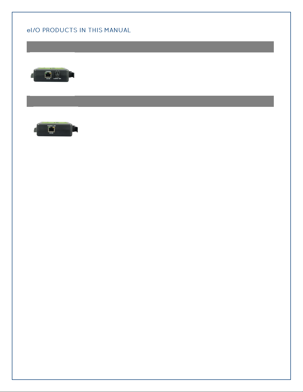
Ethernet 10/100 BaseT
eI/O 110E – 4 Optically Isolated Inputs/4 Form A Reed Relay Outputs
eI/O 120E – 4 Optically Isolated Inputs/4 Form C Relay Outputs
eI/O 130E – 4 Optically Isolated Inputs
eI/O 140E – 4 Form A Reed Relay Outputs
eI/O 150E – 4 Form C Relay Outputs
Power Over Ethernet
eI/O 110PoE – 4 Optically Isolated Inputs/4 Form A Reed Relay Outputs
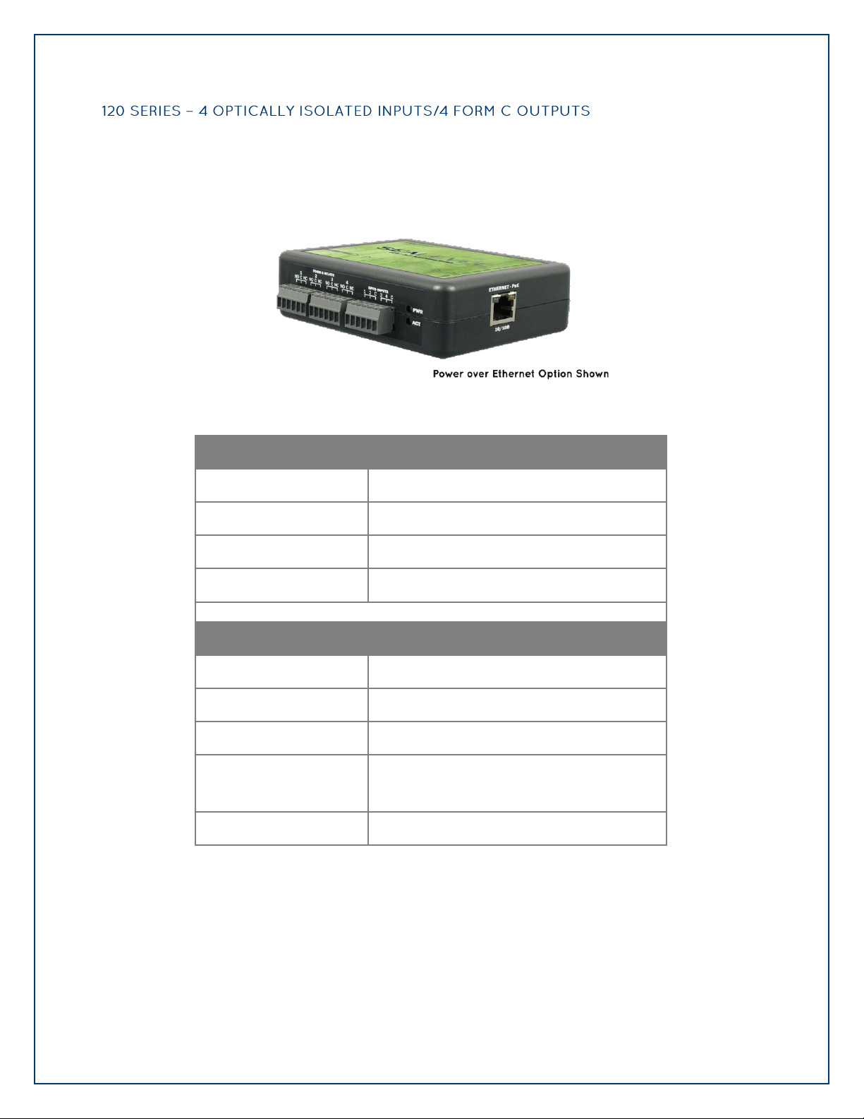
eI/O 120PoE – 4 Optically Isolated Inputs/4 Form C Outputs
eI/O 130PoE – 4 Optically Isolated Inputs
eI/O 140PoE – 4 Form A Reed Relay Outputs
eI/O 150PoE – 4 Form C Relay Outputs
Page 7
©Sealevel Systems, Inc.
SL9049 - 03/2011
eI/O Manual
7
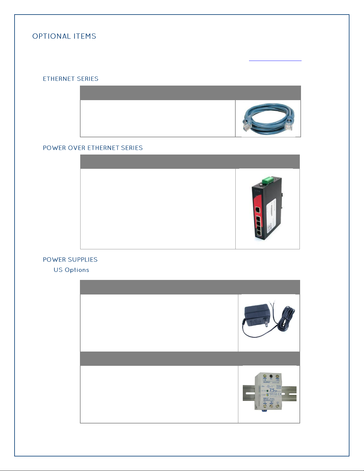
Depending on the interface type, your eI/O module may include additional accessories. Included
CAT5 Patch Cable (Part# CA246)
Standard 7' CAT5 UTP Patch Cable (RJ45).
Power Over Ethernet Switch
Connect up to four eI/O modules without power cables
with the Sealevel unmanaged five port Ethernet switch.
eI/O 120VAC to 12VDC @ 500mA Wall Mount Power Supply (Part# TR104)
The TR104 is a wall wart style power supply capable of
powering a single eI/O module at 120VAC input and
12VDC output at 500mA. Other power supply options are
available for driving multiple eI/O modules on a DIN rail.
100-240VAC to 24VDC @ 300mA DIN Rail Power Supply (Part# PS101)
The PS101 is an AC/DC DIN rail mount power supply that
accepts 100-240VAC input and outputs 24VDC at up to
300mA (7.5W).
accessories are listed below. All items can be purchased from our website (www.sealevel.com) by
calling our sales team at (864) 843-4343.
Page 8
©Sealevel Systems, Inc.
SL9049 - 03/2011
eI/O Manual
8
100-240VAC to 24VDC @ 2.1A DIN Rail Power Supply (Part# PS103)
The PS103 is an AC/DC DIN rail mount power supply that
accepts 100-240VAC input and outputs 24VDC at up to
2.1A (50W).
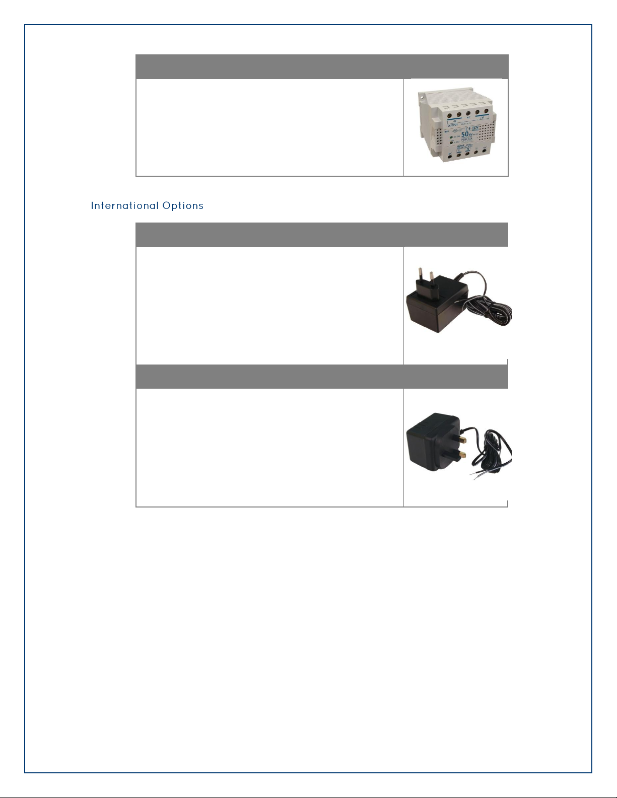
eI/O 230VAC to 12VDC @ 500mA Wall Mount Power Supply (Part# TR105)
The TR105 is a wall wart style power supply for European
countries and is rated for 230VAC input and 12VDC
output at 500mA.
eI/O 240VAC to 12VDC @ 500mA Wall Mount Power Supply (Part# TR106)
The TR106 is a wall wart style power supply for the
United Kingdom, Hong Kong, Singapore, and Malaysia.
The TR106 is rated for 240VAC input and 12VDC output
at 500mA.
Page 9
©Sealevel Systems, Inc.
SL9049 - 03/2011
eI/O Manual
9
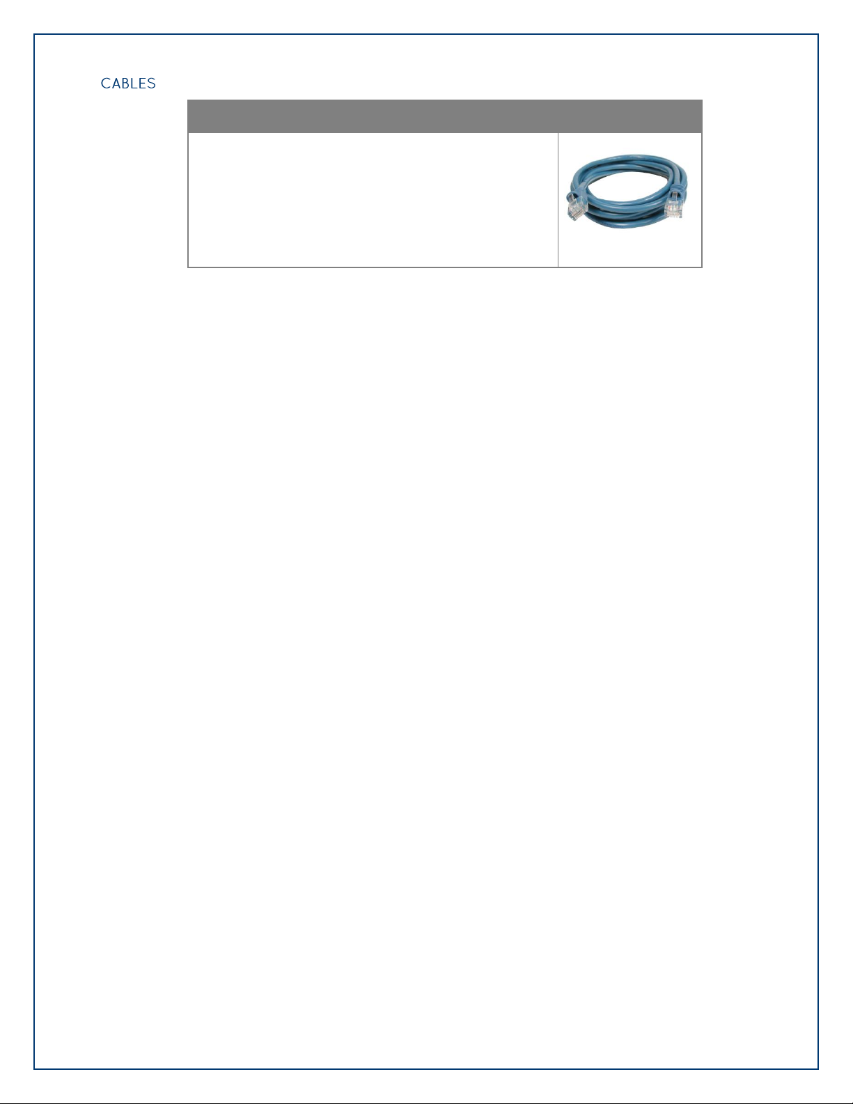
CAT5 Patch Cable, 10' in Length (Part# CA247)
10‟ Blue Ethernet Patch Cable. Can be used to connect
eI/O Ethernet modules to a hub or switch.
Page 10
©Sealevel Systems, Inc.
SL9049 - 03/2011
eI/O Manual
10
eI/O modules are powered in one of two ways
9-30 V DC power inputs
802.3af-2003 Power over Ethernet
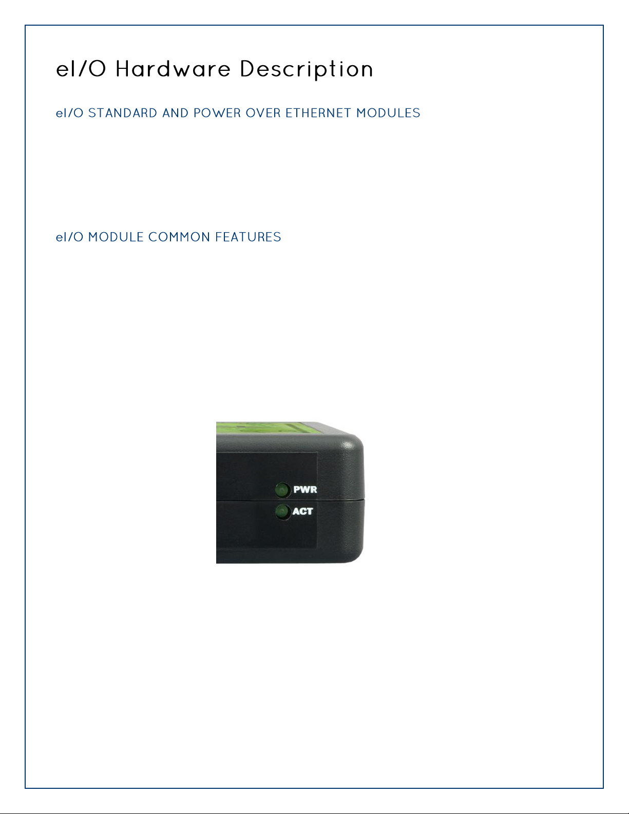
All eI/O modules include the same connectors and configuration options on the front and side of
the unit:
Status LEDs are also included on the front of all eI/O modules to indicate the following information:
Power (Green) – Lights when power is applied to the module.
Act (Green) – Light blinks when Modbus/TCP activity is present or when new firmware is
being downloaded.
Page 11
©Sealevel Systems, Inc.
SL9049 - 03/2011
eI/O Manual
11
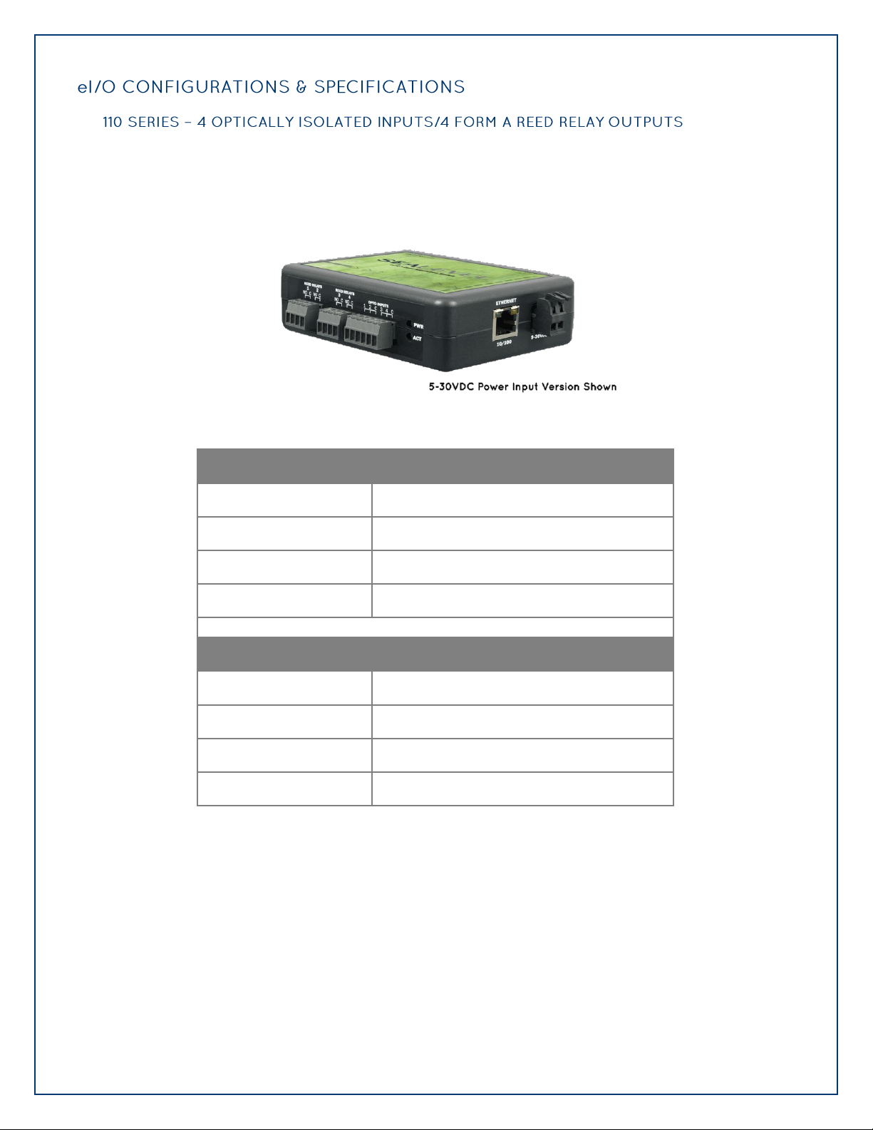
eI/O-110 modules provide 4 optically isolated inputs and 4 Form A Reed Relay outputs. Inputs
Inputs
Type
4 non-polarized optically isolated inputs
Voltage Range
5-30VDC
Isolation
2500VAC RMS / 3500VDC
Input Resistance
6.2K Ohms in series
Outputs
Type
4 SPST Form A Form A Reed Relays
Power
DC 30W / AC 10VA Max.
Contact Voltage
60VDC max.
Contact Current
500mA max.
can range from 5-30VDC, while the Form A Reed Relays provide long life switch closures that
are well suited for low current applications. Each pair of inputs shares a common and field
wiring is simplified via 3.5mm field removable terminal blocks.
Page 12
©Sealevel Systems, Inc.
SL9049 - 03/2011
eI/O Manual
12
Inputs
Type
4 non-polarized optically isolated inputs
Voltage Range
5-30VDC
Isolation
2500VAC RMS / 3500VDC
Input Resistance
6.2K Ohms in series
Outputs
Type
4 SPDT Form C relays
Power
DC 240W / AC 1200 VA
Contact Voltage
60VDC / 250VAC max. (5VDC min.)
Contact Current (DC)
<30 VDC @ 5A max.
>30 VDC @ 700mA max. (100mA min.)
Contact Current (AC)
6A max.
The eI/O-120 provides 4 optically isolated inputs and 4 SPDT Form C relay outputs. Inputs can
range from 5-30VDC and provide 300V isolation to ground, while the high current Form C
relays switch up to 60VDC @ 5A or 250VAC @ 6A. Each Form C relay has a discrete common
and includes normally-open and normally-closed contact connections. Each pair of inputs shares
a common and field wiring is simplified via 3.5mm field removable terminal blocks.
Page 13

©Sealevel Systems, Inc.
SL9049 - 03/2011
eI/O Manual
13
eI/O-130 modules provide 4 optically isolated inputs with 2500VAC RMS / 3500VDC external
Inputs
Type
4 non-polarized optically isolated inputs
Voltage Range
5-30VDC
Isolation
2500VAC RMS / 3500VDC
Input Resistance
6.2K Ohms in series
isolation and high channel-to-channel isolation. Each pair of inputs shares a common and field
wiring is simplified via 3.5mm field removable terminal blocks.
Page 14

©Sealevel Systems, Inc.
SL9049 - 03/2011
eI/O Manual
14
The eI/O-140 provides 4 SPST Form A dry-contact Form A Reed Relays. Form A Reed Relays offer
Outputs
Type
4 SPST Form A Form A Reed Relays
Power
DC 30W / AC 10VA Max.
Contact Voltage
60VDC max.
Contact Current
500mA max.
long life performance and fast response time. Convenient removable 3.5mm screw terminal
blocks compatible with 14-22 AWG wiring allow reliable connection to real world I/O.
Page 15

©Sealevel Systems, Inc.
SL9049 - 03/2011
eI/O Manual
15
The eI/O-150 provides 4 optically isolated inputs and 4 SPDT Form C relay outputs. Inputs can
Outputs
Type
4 SPDT Form C relays
Power
DC 240W / AC 1200 VA
Contact Voltage
60VDC / 250VAC max. (5VDC min.)
Contact Current (DC)
<30 VDC @ 5A max.
>30 VDC @ 700mA max. (100mA min.)
Contact Current (AC)
6A max.
range from 5-30VDC and provide 300V isolation to ground, while the high current Form C
relays switch up to 60VDC @ 5A or 250VAC @ 6A. Each Form C relay has a discrete common
and includes normally-open and normally-closed contact connections. Field wiring is simplified
via 3.5mm field removable terminal blocks.
Page 16

©Sealevel Systems, Inc.
SL9049 - 03/2011
eI/O Manual
16
eI/O standard units are powered from a 9-30VDC source using the screw terminals on the side of
Standard Series
Power Over Ethernet Series
eI/O-110
1.5W
2.2W
eI/O-120
2.0W
2.6W
eI/O-130
1.5W
2.2W
eI/O-140
1.5W
2.2W
eI/O-150
2.0W
2.6W
the unit. Sealevel offers several power supply choices to make connection easy (see the Accessories
chapter at the end of this document).
The eI/O PoE units are Class 0 (IEEE 802.3af-2003) Power over Ethernet devices. This allows power
and data to be transferred over a single CAT5 cable and eliminates the need for an external power
supply. With PoE, power can be supplied by power sourcing equipment including PoE switches
(midspans) and injectors.
Page 17

©Sealevel Systems, Inc.
SL9049 - 03/2011
eI/O Manual
17
The SeaMAX Suite is a collection of configuration/diagnostic utilities and software libraries that
enable rapid application development. The SeaMAX API, included in the SeaMAX Suite, provides a
common API for Sealevel eI/O and SeaDAC data acquisition modules. SeaMAX is designed to
simplify application development by requiring little knowledge of the underlying communication
protocols of these devices and replacing low-level programming. SeaMAX is available in an
unmanaged library and a wrapper library that provides an interface to the API from managed code.
The following libraries and utilities are included in the SeaMAX Suite and are covered in this
chapter:
MaxSSD Configuration & Diagnostics utility
Ethernet Config utility
SeaMAX API
SeaMAX .NET API
The SeaMAX API documentation, installed with SeaMAX, explains the usage and API references,
including function calls and enumerations. Sealevel digital and analog I/O modules supported by
SeaMAX software are designed to work with third party applications via the SeaMAX API. To help
simplify application development, the complete API documentation and code samples are
automatically installed with the SeaMAX Suite and can be found in Windows by clicking Start All
Programs Sealevel Systems SeaMAX Documentation. For convenience, Sealevel offers a PDF
version of the SeaMAX manual on our website. Example code is also included for several popular
languages and compilers.
Please contact Sealevel technical support with any questions regarding SeaMAX documentation:
Phone: (864) 843-4343
Email: support@sealevel.com
Sealevel eI/O modules are designed to integrate seamlessly into existing Modbus/TCP networks.
The supported command set will vary depending on the eI/O model number used. Specialized
diagnostic commands and other RTU specific codes are not supported. An overview of the Modbus
specification for TCP connections is covered in detail in the interactive documentation located on
the Sealevel website at http://www.sealevel.com/software/SeaMAX/
The official Modbus specification can be found at http://www.modbus.org.
Page 18

©Sealevel Systems, Inc.
SL9049 - 03/2011
eI/O Manual
18
Proceed with installing the SeaMAX Software Suite using the software disk that was included with
your Sealevel I/O module. Software drivers are also available on the product webpage on the
Sealevel website at www.sealevel.com.
To install Sealevel Systems software, you must log in as an administrator or have
administrator privileges in Windows.
1. Insert the Sealevel Systems disk in to your optical drive.
2. If „AutoRun‟ is enabled for this drive the software will automatically launch.
3. Otherwise, navigate to the root directory of your optical drive and double-click the
„autorun.exe‟ application to launch the installation window.
4. Select „Install‟.
Page 19

©Sealevel Systems, Inc.
SL9049 - 03/2011
eI/O Manual
19
5. Type the part number for your adapter in the text box and click „Enter‟, or click on
the drop box to scroll from the listing to select your product.
If you installed your hardware prior to loading/installing the drivers, please click on the
„Click here if you installed hardware before software‟ button and follow the listed
instructions.
6. Click the „Install Drivers‟ button to launch the Installation Wizard.
7. When the InstallShield Wizard‟ window appears, click the „Next‟ button to initiate the
software installation.
8. When the „License Agreement‟ window appears, accept the terms and click „Next‟ to
continue. You can click the „Print‟ button to print out a copy of the agreement for
your records. If you do not accept the terms of the agreement, the installation will
stop.
9. When the „Ready to Install the Program‟ window appears, click the „Install‟ button to
install the software onto the hard drive of your computer. The files will be
automatically installed into the „C:\Program Files‟ folder on your computer.
10. The setup file will automatically detect the operating environment and install the
proper components. Next follow the information presented on the screens that
11. Refer to the Physical Installation section to connect and install your adapter.
follow. Once the installation is complete, close the disk installation window.
Page 20

©Sealevel Systems, Inc.
SL9049 - 03/2011
eI/O Manual
20
1. To install the driver executable from the Sealevel disk, browse the Sealevel Systems
disk for: Software\SeaMAX\Windows\SeaMAX Installer.exe
2. If you are using Windows Vista or newer operating systems, right click on the
installer executable and choose ‟Run as Administrator‟. If you are using an operating
system prior to Windows Vista, double click on the executable to launch the
Installshield and initiate the driver installation.
3. Please refer to step six above in the Disk Installation section and follow the
remaining installation steps.
1. To obtain the most current software driver package from Sealevel‟s website,
download from here:
SeaMAX for Windows
SeaMAX for Linux
2. Choose the link for the target operating system and click on the „Download File‟ link
to download the current driver.
3. Once downloaded, if you are using Windows Vista or newer operating systems, right
click on the installer executable and choose ‟Run as Administrator‟. If you are using
an operating system prior to Windows Vista, double click on the executable to
launch the Installshield and initiate the driver installation.
4. Please refer to step six above in the Disk Installation section and follow the
remaining installation steps.
1. Download the current SeaMAX driver using the instructions from the „Downloaded
Software Installation‟ section above. Please take note of the destination directory to
which it will save.
2. Uninstall the currently loaded driver SeaMAX driver found in the Control Panel. Prior
to Windows Vista, SeaMAX will be populated in the „Add/Remove Programs‟ list. In
Windows Vista and newer operating systems, it will be found in the „Programs and
Features‟ list.
3. Navigate to the Device Manager and remove the Sealevel digital I/O adapter by right
clicking on the line item under „SeaI/O Device‟ and choosing „Uninstall‟.
Page 21

©Sealevel Systems, Inc.
SL9049 - 03/2011
eI/O Manual
21
4. In the Device Manager under „Action‟, choose „Scan for hardware changes‟. This will
prompt the installation of the adapter and associate it with the newly installed
SeaMAX driver.
The Sealevel Systems configuration utility, MaxSSD, is designed to simplify the installation,
configuration, and diagnostics of Sealevel I/O modules. MaxSSD is a Microsoft Windows application
and has been tested with Windows 2000, XP, Vista and Windows 7.
When you run the MaxSSD utility (Start All Programs Sealevel Systems SeaMAX
MaxSSD Configuration Utility) it will default to the “Host PC Configuration” tab. This tab allows
the user to choose the initial communication settings for the connected I/O device. The “COM
Port” dropdown box allows the selection of a serial COM port (from COM1 to COM256), and
Ethernet (for Ethernet and Wireless Sealevel I/O modules).
To communicate with an eI/O module, select “ETHERNET” from the “COM Port” dropdown box.
When Ethernet is selected, MaxSSD searches for any SeaI/O Ethernet or Wireless modules on the
network and displays their IP addresses in the “Available Ethernet Devices” list box (not shown).
When an IP address is selected from the list box, a socket is opened to the SeaI/O module and it
is ready for communication.
If no IP address is shown when using Ethernet modules, review the previous Hardware
Configuration section, or proceed to the Troubleshooting section at the end of this manual.
Page 22

©Sealevel Systems, Inc.
SL9049 - 03/2011
eI/O Manual
22
Once the host computer is configured correctly, the “SeaI/O Configuration” tab becomes
available. Before communicating with an eI/O module, the configuration utility must determine
if there is an I/O module, and if so, what type of module it is. This is the purpose of the Get
operation.
The eI/O modules will respond to any Slave ID so just use the default.
Click the “Get SeaIO Module Settings” button. After a short delay, the information for that I/O
module should be displayed. If no information appears, verify that the host settings are correct
and make changes if necessary.
Page 23

©Sealevel Systems, Inc.
SL9049 - 03/2011
eI/O Manual
23
After the Get command is executed, the “Module Description” frame will display the model type,
description, firmware version number, interface, and I/O type. In the example shown, the
module found at slave ID 1 is an eI/O-120 module with a PoE (Modbus TCP) interface
After a successful Get operation, additional tabs may be displayed in MaxSSD, depending on the
device model found. These tabs display device I/O and allow easy configuration for all SeaMAX
supported devices.
Page 24

©Sealevel Systems, Inc.
SL9049 - 03/2011
eI/O Manual
24
The „Digital IO‟ tab of MaxSSD is displayed when using Sealevel I/O devices featuring discrete
inputs and outputs. It displays the device‟s current input and/or output status in an intuitive
and usable manner.
When banks of inputs are displayed, the status LEDs update on each of the banks automatically.
This allows you to actively monitor external signals.
With a bank of outputs, the output coils can be set using the buttons below each output LED. As
each coil is set, the I/O module is read. The corresponding status LED in the „Digital IO‟ tab
indicates the state of the coil. In the example below, an eI/O module with 4 optically isolated
inputs and 4 Form C relays is shown.
Page 25

©Sealevel Systems, Inc.
SL9049 - 03/2011
eI/O Manual
25
Following these simple steps can eliminate most common problems.
1. Read this manual thoroughly before attempting to install the device in your system.
2. Uninstall any previous versions of the SeaMAX software before installing any new
versions.
3. Install SeaMAX software before connecting any Sealevel I/O devices. Installing
the software places the necessary files in the proper locations on your system. After
installing the software, proceed with adding the hardware.
4. Confirm that all screw terminal connections are correct and secure and that the
correct cables are being used, including network cables (crossover vs. patch cables).
5. Use the MaxSSD utility, included on the software CD, to verify proper installation.
MaxSSD is designed to simplify the installation, configuration, and diagnostics of
Sealevel SeaI/O modules.
6. Refer to the Troubleshooting Ethernet eI/O Modules section on the following page
for additional steps regarding eI/O modules.
7. If these steps do not solve your problem, please contact Sealevel Technical Support.
Our technical support is free and available from 8:00am – 5:00 pm EST, Monday
through Friday. You can contact Technical Support via email at
support@sealevel.com or by phone at +1 (864) 843-4343.
Page 26

©Sealevel Systems, Inc.
SL9049 - 03/2011
eI/O Manual
26
Problem: The eI/O module starts up with a strange IP address (i.e., 192.168.42.253).
All eI/O modules are shipped with enabled static IP address of 192.168.42.253. Also if the device is
set to DHCP, and no DHCP server is available or the DHCP server cannot be reached, eI/O modules
default to an IP address of 192.168.42.253. Change the PC‟s network settings to place both the
eI/O module and PC on the same subnet. Adjust the eI/O module‟s IP address and Netmask using
the Ethernet Config utility (Start All Programs Sealevel Systems SeaMAX Ethernet
Configuration Tool) installed with SeaMAX. Then restore the PC‟s network settings.
Problem: The eI/O module is visible in Ethernet Config, but the network settings cannot be
changed.
The eI/O module is most likely on a different subnet than the PC. The PC‟s IP address and Netmask
must be altered to place both the eI/O module and the PC within the same subnet. Contact your
network administrator for assistance.
Problem: The eI/O module doesn’t show up in Ethernet Config.
eI/O modules are discovered via a UDP broadcast. Verify that any firewall software, such as
Windows Firewall, ZoneAlarm, etc., or router settings that would hinder UDP transmissions are
disabled.
It is also possible that the eI/O module may not be discovered if the PC and module are on separate
subnets. This may occur if the module‟s IP address is configured outside the range of the PC‟s
subnet. It can also occur during a failed DHCP discovery. In either case, the “Recover Module”
button in Ethernet Config utility may be used to recover the device. Refer to the Hardware
Configuration section of this manual for more information.
Page 27

©Sealevel Systems, Inc.
SL9049 - 03/2011
eI/O Manual
27
Verify that SeaMAX software has been installed successfully and that an eI/O module is connected
directly to your computer using the yellow crossover cable supplied with your module.
All eI/O modules are shipped with DHCP enabled. When you first connect an eI/O module to the
network, the status LEDs on the front of the module will blink while it searches for a DHCP server.
Once it receives an IP address, the status LEDs will remain on.
If no DHCP server is available, the eI/O module will default to a random IP address in the range
169.254.x.x. To discover the eI/O module‟s IP address, start the Ethernet Config utility (Start All
Programs Sealevel Systems SeaMAX Ethernet Configuration Tool) installed with SeaMAX.
Click on the “Search for SeaI/O Devices” button and the „Available SeaI/O Devices‟ pane should
refresh with any Ethernet or Wireless SeaI/O and any eI/O modules that are found on the network.
Select one of the modules in the list by clicking on it. You can update the settings in the Device
Network Settings pane and then confirm these changes by clicking the “Apply Changes” button.
The module list should refresh, indicating that your changes were successful.
Start MaxSSD (Start All Programs Sealevel Systems SeaMAX MaxSSD Configuration Utility)
and choose the correct IP address to communicate with the eI/O module. Ensure a successful Get
operation (refer to the MaxSSD section of this manual for more information).
Page 28

©Sealevel Systems, Inc.
SL9049 - 03/2011
eI/O Manual
28
An eI/O module may become no longer visible in the module list in the Ethernet Config utility if
the eI/O module has been configured to use a different subnet than the host computer.
In other cases, the eI/O module doesn‟t appear in the module list due to a DHCP discovery
failure. In either case, clicking on the “Recover Module” button (see image on previous page) in
the Ethernet Config utility will bring up the “Module Reset” window shown below.
Before recovery begins, make certain that the PC and eI/O module are on the same network
segment – they should be connected with an Ethernet crossover cable, through a hub, or
through a non-routing switch. eI/O modules are shipped with an Ethernet patch cable (blue).
Next, select the IP Address of the network card your device is connected to from the dropdown
labeled “Network Interface.”
Enter the MAC address found on the label on the bottom of the eI/O enclosure. A MAC address
is made up of six pairs of hex digits separated by dashes (i.e., xx-xx-xx-xx-xx-xx). While
entering the MAC address, the indicator to the right of the field will turn red if the MAC address
entered is invalid. Once a MAC address is successfully entered, the indicator light will turn
green and the “Network Settings” options will be enabled.
Contact your network administrator if you are unsure of the proper network settings to choose.
If a DHCP server is available, select the “Enable DHCP Configuration” checkbox. Otherwise,
complete the network settings and click the “Recover Module” button to complete the
configuration changes.
Page 29

©Sealevel Systems, Inc.
SL9049 - 03/2011
eI/O Manual
29
Modules with version “2” or higher support several Advanced Features. You may determine the
version of your SeaIO device using the MODBUS command FUNC_SEAMAX_GET_EXTENDED_INFO
(0x66), using the SeaMAX method SM_GetDeviceConfig(), or by viewing the Module Description
in MaxSSD, shown below.
In the event that a newer version of the firmware is available, it is possible to upgrade the
firmware in the unit. This can be done through the same port that is used to do normal
communications with the unit. The unit must be directly connected to the programming
computer.
This will be a file with a name similar to your eI/O model number with an extension of “.hex”.
As an example, it you have a eI/O 120 style module, the programming file name would be
“120.hex”. Please contact Tech Support to receive the latest version of the firmware.
The device‟s firmware can be upgraded in one of two ways. The first is through the command
prompt. The second, preferred method, is through the MaxSSD Configuration Utility.
To execute IOCU.exe from a command prompt, Click on Start, then click Run and type “cmd”
(without the quotation marks and hit enter. You will then see a command prompt (ie.
c:\documents and settings\name>). Once you are at the command prompt, browse to your
SeaMAX folder. The default location is “C:\Program Files\Sealevel Systems\SeaMAX\”. Your
*.hex file will need to be saved to this folder as well.
Page 30

©Sealevel Systems, Inc.
SL9049 - 03/2011
eI/O Manual
30
Type
Cd “C:\Program Files\Sealevel Systems\SeaMAX\” and then press Enter
When the command calls for iii.iii.iii.iii you substitute the unit‟s IP address. Please do not enter
the numbers with a leading zero. Therefore, if your IP address is 192.168.42.11, you will enter
192.168.42.11 and not 192.168.042.011. The command for this is therefore:
iocu /i=192.168.42.11 /a=247 120.hex
Once the unit has received the download request it will turn on the ACT light . Once the
download starts, the ACT light will flash rapidly as data is downloaded. Once the download is
complete, the ACT light will remain on while the device is reprogramming itself.The unit will
then reboot itself to reload the new firmware. At this point, the ACT light will turn off.
The above should only be performed if you (1) really feel the update is required and (2)
you feel confident in your ability to perform the update. Once the firmware has been
erased, you must either be able to re-program it locally or send it back to SeaLevel
Systems, Inc. for reprogramming.
To upgrade your firmware through MaxSSD, connect to your device normally, then go to the
“Advanced” tab. At this point, you can use the “…” button to browse for the *.hex file you wish
to update your device with.
Page 31

©Sealevel Systems, Inc.
SL9049 - 03/2011
eI/O Manual
31
Once the proper file has been selected, click on the “Flash Firmware” button.
At this point, SeaMAX will give you a warning dialog. If you click “OK” then MaxSSD will attempt
to flash your device with new firmware. If you click on the “Cancel” button, no changes will be
made.
Clicking “OK” will result in IOCU.exe being run in a terminal window. Once the unit has received
the download request it will turn on the ACT light. Once the download starts, the ACT light will
flash rapidly as data is downloaded. Once the download is complete, the ACT light will remain
on while the device is reprogramming itself.The unit will then reboot itself to reload the new
firmware. At this point, the ACT light will turn off, and the terminal window will close. MaxSSD
will return you to the Host PC Configuration tab.
Exercise caution when performing a firemware upgrade to ensure that the process does
not get interrupted until the process completes. Once the firmware has been erased, you
must either be able to re-program it locally or send it back to Sealevel Systems, Inc. for
reprogramming.
Page 32

©Sealevel Systems, Inc.
SL9049 - 03/2011
eI/O Manual
32
Optically isolated inputs are arranged such that each pair shares a single common. The four I/O
points and shared commons are connected via a six-position removable screw terminal. Input
voltage range is 5-30VDC. Unlike the inputs, each Reed relay utilizes a single common and
connects via a four-position removable screw terminal. Form C Relay outputs are arranged such
that each relay has a common. The NC and NO contacts of two relays along with the commons
are brought out via a six-position removable screw terminal.
Page 33

©Sealevel Systems, Inc.
SL9049 - 03/2011
eI/O Manual
33
eI/O Ethernet connector is used for both data and power in the PoE series of modules. Both DC
Pin
Signal
PoE Mode A
PoE Mode B
1
TX+
TX+/DC+
TX+
2
TX-
TX-/DC+
TX-
3
RX+
RX+/DC-
RX+
4
N/A
N/A
DC+
5
N/A
N/A
DC+
6
RX-
RX-/DC-
RX-
7
N/A
N/A
DC-
8
N/A
N/A
DC-
on spares (Mode B) and mixed DC and data (Mode A) Power over Ethernet 802.3af-2003
configurations are acceptable for the eI/O. The eI/O PoE series modules are class 0 power over
Ethernet devices.
Page 34

©Sealevel Systems, Inc.
SL9049 - 03/2011
eI/O Manual
34
eI/O modules ship ready for mounting on DIN rail. A small, rugged
plastic (shown below) is included that naps onto 35mm DIN rail. This
offers a clean installation by locating the I/O modules near the
industrial control equipment on the DIN rail. Additionally, 3.5mm
removable screw terminals allow for an easy and reliable connection
method.
As an alternative to DIN rail, the versatile plastic clip includes
mounting holes that allow eI/O modules to be mounted to walls,
under counters, or inside panels. The plastic clip can be permanently
mounted to a surface while still allowing the eI/O module to be easily
removed for service or configuration changes.
eI/O modules are perfect for table or desktop use. The units
ship with four rubber feet that help prevent the devices from
sliding due to vibration and help protect surfaces from
scratches. The small enclosures take up very little space.
Page 35

©Sealevel Systems, Inc.
SL9049 - 03/2011
eI/O Manual
35
A sudden electrostatic discharge can destroy sensitive components. Proper packaging and
grounding rules must therefore be observed. Always take the following precautions:
Transport boards and cards in electrostatically secure containers or bags.
Keep electrostatically sensitive components in their containers, until they arrive at an
electrostatically protected workplace.
Only touch electrostatically sensitive components when you are properly grounded.
Store electrostatically sensitive components in protective packaging or on anti-static mats.
The following measures help to avoid electrostatic damages to the device:
Cover workstations with approved antistatic material. Always wear a wrist strap connected
to workplace as well as properly grounded tools and equipment.
Use antistatic mats, heel straps, or air ionizers for more protection.
Always handle electrostatically sensitive components by their edge or by their casing.
Avoid contact with pins, leads, or circuitry.
Turn off power and input signals before inserting and removing connectors or connecting
test equipment.
Keep work area free of non-conductive materials such as ordinary plastic assembly aids and
Styrofoam.
Use field service tools such as cutters, screwdrivers, and vacuum cleaners which are
conductive.
Always place drives and boards PCB-assembly-side down on the foam.
Page 36

©Sealevel Systems, Inc.
SL9049 - 03/2011
eI/O Manual
36
When calling for technical assistance, please have the device installed and ready to run diagnostics.
If possible, have your user manual and current settings ready.
The Sealevel website is an excellent resource located at www.sealevel.com. The most current
software updates and user manuals are available via our homepage by clicking on the 'Drivers' or
'Manuals' links located under „Technical Support.‟ Manuals and software can also be downloaded
from the product page for your device.
The FAQ section of our website answers many common questions. Refer to this helpful resource
by visiting www.sealevel.com/faq.asp.
Monday – Friday
8:00 am to 5:00 pm EST
Phone: +1 (864) 843-4343
Email: support@sealevel.com
RETURN AUTHORIZATION MUST BE OBTAINED FROM SEALEVEL SYSTEMS BEFORE RETURNED
MERCHANDISE WILL BE ACCEPTED. AUTHORIZATION CAN BE OBTAINED BY CALLING SEALEVEL
SYSTEMS AND REQUESTING A RETURN MERCHANDISE AUTHORIZATION (RMA) NUMBER.
Page 37

©Sealevel Systems, Inc.
SL9049 - 03/2011
eI/O Manual
37
Sealevel's commitment to providing the best I/O solutions is reflected in the Lifetime Warranty that
is standard on all Sealevel manufactured I/O products. Relio™ industrial computers are warranted
for a period of two years and the R9 family is warranted for a five year period from date of
purchase. We are able to offer this warranty due to our control of manufacturing quality and the
historically high reliability of our products in the field. Sealevel products are designed and
manufactured at its Liberty, South Carolina facility, allowing direct control over product
development, production, burn-in and testing. Sealevel achieved ISO-9001:2000 certification in
2002.
Sealevel Systems, Inc. (hereafter "Sealevel") warrants that the Product shall conform to and perform
in accordance with published technical specifications and shall be free of defects in materials and
workmanship for the warranty period. In the event of failure, Sealevel will repair or replace the
product at Sealevel's sole discretion. Failures resulting from misapplication or misuse of the
Product, failure to adhere to any specifications or instructions, or failure resulting from neglect,
abuse, accidents, or acts of nature are not covered under this warranty.
Warranty service may be obtained by delivering the Product to Sealevel and providing proof of
purchase. Customer agrees to insure the Product or assume the risk of loss or damage in transit, to
prepay shipping charges to Sealevel, and to use the original shipping container or equivalent.
Warranty is valid only for original purchaser and is not transferable.
This warranty applies to Sealevel manufactured Product. Product purchased through Sealevel but
manufactured by a third party will retain the original manufacturer's warranty.
Products returned due to damage or misuse and Products retested with no problem found are
subject to repair/retest charges. A purchase order or credit card number and authorization must be
provided in order to obtain an RMA (Return Merchandise Authorization) number prior to returning
Product.
If you need to return a product for warranty or non-warranty repair, you must first obtain an RMA
number. Please contact Sealevel Systems, Inc. Technical Support for assistance:
Available Monday – Friday, 8:00AM to 5:00PM EST
Phone 864-843-4343
Email support@sealevel.com
Sealevel Systems, Incorporated acknowledges that all trademarks referenced in this manual are the
service mark, trademark, or registered trademark of the respective company.
 Loading...