

impro technologies XTT902-1-0-GB-01, XTT905-1-0-GB-01, XTT903-1-0-GB-00, XTT904-1-0-GB-03, XTT906-1-0-GB-00 Installation Manual
...
MODEL NUMBER: XTT901-1-0-GB-XX XTT902-1-0-GB-XX
XTT903-1-0-GB-XX XTT904-1-0-GB-XX
XTT905-1-0-GB-XX XTT906-1-0-GB-XX
XTT907-1-0-GB-XX XTT908-1-0-GB-XX
XTT909-1-0-GB-XX XTT950-1-0-GB-XX
ANTENNA READERS
ImproX 125 kHz Antenna Readers
INSTALLATION MANUAL
SPECIFICATIONS
Working Environment
XTT901, XTT906, XTT908 .....
Designed to work in an indoor or outdoor
environment similar to IP66. The Antenna
Readers are, therefore, sealed (potted) against
water.
XTT902, XTT903, XTT904,
XTT907 ..................................
Designed to work in an indoor or outdoor
environment similar to IP53. The Antenna
Readers are, therefore, sealed (potted) against
water.
XTT905 ..................................
Designed to work in an indoor or protected
outdoor environment similar to IP42. The
Antenna Reader is, therefore, not sealed
against water.
XTT909 ..................................
The IP rating for this Antenna Reader is
equivalent to the selected Cabinet’s rating.
XTT950 ..................................
Designed to work in an indoor or protected
outdoor environment similar to IP54.
NOTE: Certain plastic Readers (XTT901,
XTT902, XTT905, XTT907 and
XTT908) are RoHS compliant and
do not contain any UV stabilizer.
Buzzer
Volume and Tone ...................
Single tone, 4-step adjustable volume.
NOTE: The ImproX MMA (XTT901) does
not include a buzzer.
Keypad
XTT904 and XTT907 ..............
12 Alphanumeric keys.
XTT905 ..................................
12 Numeric keys.
Status Indicators
Status LED .............................
Bi-coloured Red or Green (externally visible).

XTT301-0-0-GB-15
December 2010
Page 2
INSTALLATION INFORMATION
Accessories
Find the following when unpacking the Antenna Reader:
XTT901 to XTT904 and XTT907
Either an ImproX MMA Antenna Reader (XTT901-1-0-GB-XX) housed in a Dark
Grey, ABS Plastic housing. The ImproX MMA consists of a Front Cover and a
Backing Plate. The Front Cover (including the potted electronic components)
assembly includes 8 m (26 ft) of 4-core, 0.5 mm solid strand Communications
Cable.
Or an ImproX MA Antenna Reader (XTT902-1-0-GB-XX) housed in a Dark Grey,
ABS Plastic housing. The ImproX MA consists of a Front Cover and a Backing
Plate (the Backing Plate is attached with a Self-tapping Screw (M2 x 6 mm)).
Or an ImproX MHA Antenna Reader (XTT903-1-0-GB-XX) housed in a Zinc alloy
die-cast housing. The ImproX MHA consists of a Front Cover and a Backing Plate
(the Backing Plate is attached with a Hexagonal Screw (M3 x 8 mm)).
Or an ImproX KHA Antenna Reader (XTT904-1-0-GB-XX) housed in a Zinc alloy
die-cast housing. The ImproX KHA consists of a Front Cover and a Backing Plate
(the Backing Plate is attached with a Hexagonal Screw (M3 x 8 mm)).
Or an ImproX KA Antenna Reader XTT907-1-0-GB-XX) housed in a Dark Grey,
ABS Plastic housing. The ImproX KA consists of a Front Cover and a Backing
Plate (the Backing Plate is attached with a Self-tapping Screw (M3 x 8 mm)).
An Allen Key (2 mm) (XTT903-1-0-GB-XX and XTT904-1-0-GB-XX models only).
An extra Hexagonal Screw (M3 x 8 mm) (XTT903-1-0-GB-XX and
XTT904-1-0-GB-XX models only).
An extra Serial Number Label.
XTT905
An ImproX KMA Antenna Reader housed in a Black, ABS Plastic housing. The
ImproX KMA consists of a Front Cover and a Mounting Bracket (the Mounting
Bracket is attached with a Self-tapping Screw (M2 x 6 mm)).
Four Counter-sunk Self-tapping Screws (M2 x 6 mm).
An extra Serial Number Label.
XTT906 and XTT908
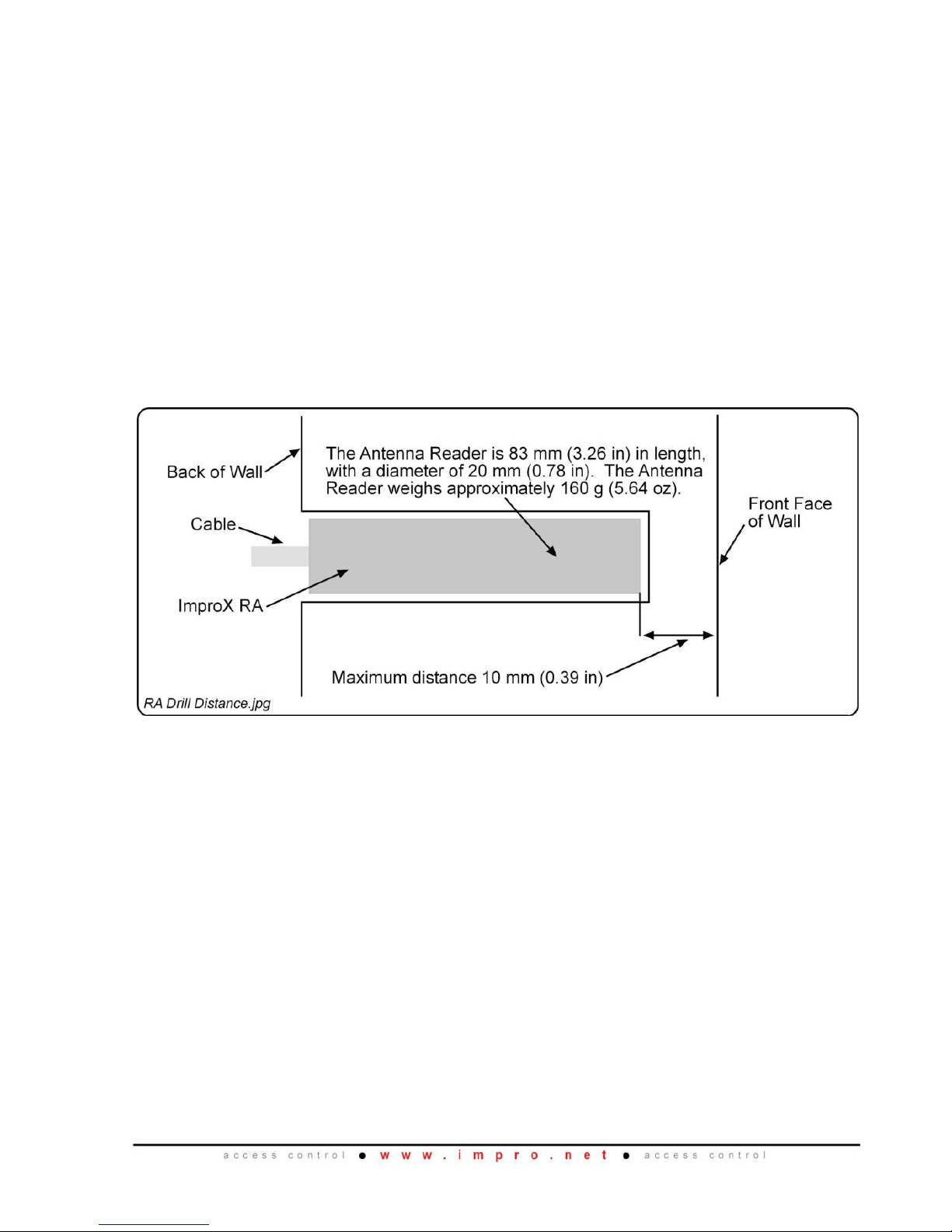
Either an ImproX RA Antenna Reader (XTT906-1-0-GB-XX) housed in PVC
sheathing. The ImproX RA includes 8 m (26 ft) of 4-core cable.
Or an ImproX DPA Antenna Reader (XTT908-1-0-GB-XX) housed in a Black, ABS
Plastic housing. The ImproX DPA includes 8 m (26 ft) of 4-core, 0.5 mm Solid
Strand Communications Cable.
A Piezo-electric, External Drive Buzzer.
A bi-colour Red or Green, White Diffused Lens, Hi-bright, 5 mm, 2-Terminal LED
(XTT906-1-0-GB-XX model only).
An extra Serial Number Label.

XTT301-0-0-GB-15
December 2010
Page 3
XTT909
Ten ImproX CA Antenna Reader printed circuit board assemblies.
An extra Serial Number Label.
XTT950
An ImproX Antenna Junction Box Reader housed in a Black, ABS Plastic housing.
The Antenna Reader consists of a Front Cover and a Backing Plate Assembly (the
Front Cover is attached with a Combi Screw (6 mm x 2.2 mm)). The Backing Plate
Assembly includes 1 m (3.28 ft) of 10-core, 6.2 mm cable.
An extra Serial Number Label.
General
Remember the following when installing the Antenna Reader:
Antenna Reader Distance
The ideal cable distance between the Terminal, Controller or Receiver and its Antenna
Reader ranges between 2 m to 16 m (7 ft to 53 ft).
NOTE: When used with the ImproX iTT or the IXP20 Controller (iTT Platform) the
ideal cable distance between the Terminal or Controller and Non-keypad
Antenna Readers ranges between 2 m to 25 m (7 ft to 82 ft). The ideal
cable distance between the Terminal or Controller and Keypad Antenna
Readers ranges between 2 m to 16 m (7 ft to 53 ft).
Optimal performance is not guaranteed outside of the range. Achieve optimal
performance by using a good quality shielded multi-strand 3-pair twisted cable. The
cross-sectional area of the cable must not be less than 0.2 mm2 (0.0003 in2).
Cable Specifications
The cable specifications should be similar to the following:
Conductor Resistance: < 2 ohms.
Capacitance, Core to Earth: < 160 pF/m.
Capacitance, Core to Core: < 100 pF/m.
Distance between Antenna Readers from the SAME Terminal, Controller
or Receiver
To avoid mutual interference, install the Antenna Readers no closer than 150 mm (6 in)
apart.
Distance between Antenna Readers from DIFFERENT Terminals,
Controllers or Receivers
To avoid mutual interference, install the Antenna Readers no closer than 500 mm
(20 in) apart.
Mounting the Antenna Readers
CAUTION: Make certain that you mount the Antenna Reader on a vibration-free
surface.
XTT301-0-0-GB-15
December 2010
Page 4
CAUTION: Once clipped together, separation of the Backing Plate and Front
Cover of the ImproX MMA (XTT901) is likely to cause damage to the
Antenna Reader.
Select the mounting position of the Antenna Reader, considering accessibility, routing
of wires and visibility of the externally visible LED.
XTT901 to XTT905, XTT907, XTT908 and XTT950
Secure the Antenna Reader to the mounting surface, using two suitable screws and
wall plugs, nuts and bolts, rivets or double-sided adhesive tape.
NOTE: The ImproX DPA is designed for mounting in a user supplied enclosure.
The Reader has 4 mounting holes, drilled to 4 mm in diameter. The
mounting holes accommodate M3 bolts and nuts.
XTT906
Secure the ImproX RA in the mounting surface, using a suitable filling agent.
Figure 1: Mounting the ImproX RA
Blank Space
 Loading...