

impro technologies HRW900-5-0-GB-XX, HRW903-5-0-GB-XX, MDR901-5-0-GB-XX, HRW901-5-0-GB-XX, HRW902-5-0-GB-XX Installation Manual
...
MODEL NUMBERs:
HRW903-5-0-GB-XX, HRW902-5-0-GB-XX
MDR901-5-0-GB-XX, MDK901-5-0-GB-XX
HRW900-5-0-GB-XX, HRW901-5-0-GB-XX
HRK900-0-5-GB-XX, HRK901-0-5-GB-XX
M
ULTI-DISCIPLINE
READERS
Impro Multi-discipline Readers
INSTALLATION MANUAL
SPECIFICATIONS
CSN Read Capability ...................
Slim Tags, Omega Tags, Impro Trinary Tags
(1074 and 2074), Philips HITAG™ 1, Philips
HITAG™ 2, HID Tags (H10301, H10302 and
H10304), ISO 15693-2 iClass Tags, ISO
18092 FeliCa Tags and ISO 14443A
MIFARE® Tags.
NOTE: HID, FeliCa and MIFARE® are
registered trademarks of HID
Global Corporation (an ASSA
ABLOY Group Brand), The Sony
Corporation and Koninklijke Phillips
Electronics N.V. respectively.
Working Environment
MDK901/HRW900
MDR901/HRW901
HRW903/HRW902.........................
Designed to work in an indoor or outdoor
environment similar to IP54. These models
are, therefore, sealed (conformal coated)
against water.
HRK900 & HRK901 .......................
Designed to work in an indoor environment
similar to IP20. These models are NOT sealed
against water and should not be exposed to
rain or splashes.
Installation
Please consult the instructions under
Installation Information, on page 4.
Blank Space

MDR300-0-0-GB-08
July 2015
Page 2
Input Voltage Rating ....................
8 V DC to 14 V DC, polarity sensitive.
NOTE: If the Multi-discipline Reader’s Input
Voltage rises or falls outside that
specified above; the Reader emits
a continuous beep sound. The
beep sound consists of a 1-second
beep followed by a 1-second
interbeep pause.
Power Requirements
Current (mA)
Power (W)
Supply Voltage 12 V DC all
Indicators on...........................
100
1.2
Wiegand Bus
Electrical Interface ..................
‘0’ and ‘1’ Data streams.
Data Format ...........................
Tag information: 44-bit or 26-bit Wiegand.
Key information: 26-bit Wiegand only.
Inputs
Quantity ..................................
4.
Type .......................................
Dry Contact.
Function .................................
Operation of the Buzzer, LED and Scanner
Inhibit.
Protection Range ...................
+15 V Continuous.
Buzzer ...........................................
4 kHz piezo-electric single volume, single tone.
HRK901 and MDK901/HRW901/HRW903 models only
Ke ypad ..........................................
12 Alphanumeric keys.
Keypad Durability ........................
Maximum 200 000 key presses.
PIN-codes .....................................
5 Digit codes in the range 00000 to 65535.
4 Digit codes in the range 0000# to 9999#.
Blank Space

MDR300-0-0-GB-08
July 2015
Page 3
Status Indicators
Status LED .............................
Tri-coloured Red, Green or Amber (Default)
(externally visible).
Optical Anti-tamper
(MDR901/HRW900,
MDK900/HRW901,
HRW903/HRW902) ................
Open Collector Output on Purple Line.
GND reference on Grey Line.
Mechanical Anti-tamper
(HRK900, HRK901) ................
Open Collector Output on Purple Line.
GND reference on Grey Line.
NOTE: In OEM applications, connect the
Purple and Grey wires to a Dry
Contact Input. In Access Portal
Systems (connecting to a Wiegand
Module clustered with a Cluster
Controller Module), and on IXP20
(iTRT version) and IXP220
Systems (when connected direct to
the Controller or via the Impro
iTRT) it is unnecessary to connect
these lines as the Software handles
the Anti-tamper.
Blank Space

MDR300-0-0-GB-08
July 2015
Page 4
INSTALLATION INFORMATION
Accessories
Find the following when unpacking the Multi-discipline Reader:
• Either an Impro (MDR) Multi-discipline Reader (MDR901-5-0-GB-XX/HRW900-5-0-
GB-XX) housed in an ABS Plastic and 304 Stainless Steel housing. The Multidiscipline Reader consists of a Front Cover assembly and a Backing Plate (the
Backing Plate is attached with a Hexagonal Screw (M3 x 8 mm)).
• Or an Impro (MDK) Multi-discipline Keypad Reader (MDK901-5-0-GB-XX/
HRW901-5-0-GB-XX) housed in an ABS Plastic and 304 Stainless Steel housing.
• OR a Multi-discipline Junction Box Reader ((HRK900-0-5-GB-XX) / Multi-discipline
Junction Box Keypad Reader ((HRK901-0-5-GB-XX) housed in a Black, ABS
Plastic housing.
The Multi-discipline Reader consists of a Front Cover assembly and a Backing
Plate (the Backing Plate is attached with a Hexagonal Screw (M3 x 8 mm)).
• One 2-Way Programming Pin.
• An Allen Key (2 mm).
• An extra Hexagonal Screw (M3 x 8 mm).
• An extra Serial Number Label.
The Junction Box Reader consists of a Front Cover and a Backing Plate Assembly
(the Front Cover is attached with a Combi Screw (6 mm x 2.2 mm)). The Backing
Plate Assembly includes 1 m (3.28 ft) of 10-core, 6.2 mm cable.
• One 2-way Programming Pin.
• An extra Serial Number Label.
General
Remember the following when installing the Multi-discipline Readers:
Maximum Data Communications Distance
Install the Multi-discipline Readers no further than 150 m (164 yd) from the Host unit.
The cable individual conductor may be AWG 20 to AWG 22 cross-sectional area should
not be less than 0.644 mm
2
(0.0253 in2).
NOTE: You can expect a drop in read range on 13.56 MHz Tags if noise exists on
the Reader’s input supply. The following good wiring practices lessen noise
introduction: Use a well shielded cable with a drain wire, ensure connection
of the drain wire to a clean Earth point. Also, install cables away from high
voltage cabling and other noise (that is wireless equipment, machinery and
so on) sources.

MDR300-0-0-GB-08
July 2015
Page 5
Distance between Multi-discipline Readers
To avoid mutual interference, install the Multi-discipline Readers no closer than
500 mm (20 in) apart. Expect a drop in Tag read range where you install Multidiscipline Readers back-to-back (that is on either side of a wall).
Mounting the Multi-discipline Readers
CAUTION: Make certain that you mount the Readers on a vibration-free
surface.
CAUTION: You may install Multi-discipline Readers in an open environment.
To do this, apply a slanted strip of general-purpose, black, silicone
based sealant between the mounting surface and the Backing Plate,
above the cable entry point. An open environment refers to any
environment affected by elements like rain or water.
Select the mounting position of the Multi-discipline Readers, considering accessibility,
routing of wires and visibility of the externally visible LED.
Secure the Multi-discipline Readers to the mounting surface, using suitable screws and
wall plugs, nuts and bolts or rivets.
Blank Space
MDR300-0-0-GB-08
July 2015
Page 6
ELECTRICAL CONNECTIONS
Connecting the Multi-discipline Reader
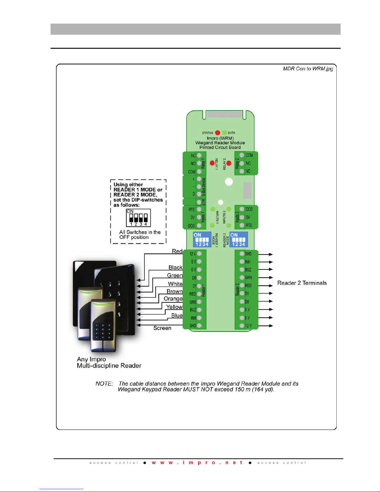
Figure 2 to Figure 7 show typical connections for the Multi-discipline Reader.
Figure 1: Multi-Discipline Reader connected to the Wiegand Reader Module
 Loading...