


MODEL NUMBER:
HMW700-0-0-NN-XX HMW701-0-0-NN-XX
Wiegand Reader
Module
Impro (WRM) Wiegand Reader Module
INSTALLATION MANUAL
SPECIFICATIONS
The WRM is a Cluster Expansion Module that works in conjunction with an Impro
(CCM) Cluster Controller Module; offering a Wiegand Reader Interface solution that is
adaptable and scalable, while also accommodating legacy hardware and software
suites.
Working Environment
Plastic Housing ............................
(HMW700)
Designed to work in an indoor (dry)
environment similar to IP20. The Module is
not sealed against water.
PCB Card for IPS / 19” Rack .......
(HMW701)
Designed to work in an indoor (dry)
environment similar to IP20. The Card is not
sealed against water.
Power
Input Voltage ................................
12 V DC to 15 V DC, polarity protected.
Power Requirements
Current (mA)
Power (W)
12 V DC with no Readers
connected and relays off ........
37
0.44
12 V DC with both relays
activated and maximum
reader load .............................
503
6

Communication with the Cluster Controller Module
Direct Communications ..............
When the WRM is clustered (plugged side-by-
side) directly into the CCM, or into an existing
Cluster, or installed as a PCB Card in IPS
Housing.
Electrical Interface .................. Proprietary Cluster-Bus
Baud Rate ..............................
115 200
Encryption .............................. AES Encryption
S-Bus Device Port
Electrical Interface ..................
Proprietary S-Bus
Baud Rate .............................. 9600
Encryption ..............................
AES Encryption
NOTE: The Wiegand Reader Module (being a Twin Reader Interface) can make
use of TWO S-Bus Addresses; this must be borne in mind when connecting
these modules to their Cluster Controller Module via S-Bus. No more than
eight Addresses should share an S-Bus. See WRM Address Information
on page 17 for Address usage with one Reader connected.
Reader Options
Reader 1 Wiegand and Reader 2 Wiegand allow connection to the following hardware:
Impro (MDR) Multi-discipline Reader, Impro (XFM) Multi-mode Remotes, Wiegand
Readers, Impro (IR) Infrared Receiver or the Impro (QR) Quad Receiver. The function
is selectable via the DIP-switches (See Table 1).
Power Output ...............................
12 V DC and 5 V DC (selectable) at maximum
200 mA.
Modes Supported
........................
Tag + PIN-code or Reason Code.
Baud Rate .....................................
9 600.
Data Format ..................................
8 data bits, no parity, 1 stop bit.
Electrical Interface .......................
TTL Full Duplex.
Communications Protocol ..........
Impro Proprietary Protocol.
Relays
Relay Output ................................
2 Relays, Form C, each with NO, COM and
NC contacts.
Relay Contact Ratings
.................
10 A at 28 V DC,
5 A at 220 V AC,
10 A at 120 V AC.
Operations ....................................
100 000 Minimum.
HMW300-0-0-GB-00 October 2013 Page 2
Digital Inputs
General
Type .............................................
2 Dry-contact inputs with End-of-line (EOL)
Sensing and 2 Dry-contact inputs without End-
of-line (EOL) Sensing.
Detection Resistance Range ......
< 2 kOhm.
Protection Range .........................
+15 V continuous.
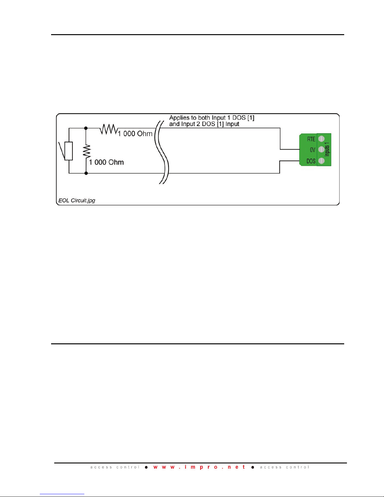
Figure 1: End-of-line (EOL) Sensing Circuit
NOTE: End-of-line (EOL) Sensing enables the WRM to raise an alarm when
somebody tampers with the circuit (cutting or shorting the wires) between
either Reader 1 Inputs [1] DOS or Reader 2 Inputs [2] DOS and GROUND
(GND). In other words the Module distinguishes between tampering on the
circuit, and the door being in an actual ‘Normally Open’ state.
By placing Resistors into the circuit between either Reader 1 Inputs DOS [1]
or Reader 2 Inputs DOS [1] and GROUND (GND), the Module’s Digital Input
monitors a constant resistance through the circuit. When the circuit is
tampered with, the Resistors are bypassed; the Module detects the
resistance change and raises an alarm.
LED Status and Diagnostic Indicators
Status LED (RED)
Supply Voltage Status ............
Off when supply voltage is too high, or too low
Upgrade Mode .......................
Flashing at a steady rate during upgrade
Communications Failure ........
Two brief flashes, repeating
Data LED (GREEN)
Flashing Green during communication
Digital Inputs (1-4) ......................
Continuous Green on detected contact closure
Relays (1 and 2) ...........................
Continuous Red on activation of the Relay
HMW300-0-0-GB-00 October 2013 Page 3

INSTALLATION INFORMATION
Accessories
CAUTION: DO NOT use the Metal-oxide Varistors (25 Vrms, 500 A, 77 V max
clamping) with mains power applications.
Plastic Cluster Housing (HMW700)
Each Impro (WRM) Wiegand Reader Module is supplied in a Customisable Black, ABS
Plastic housing, with the following features / items:
• Housing, consisting of a Base, a Cover and a selection of Cable Entry Gland
Plates.
• The Housing Base has:
− Two slots to hold the User-Selectable Cable Entry Plates
− Six knock-out Cable Entry Points
− Four Drill-out Cable Entry Points
• The Housing Cover and Base are held together with two Allen Head Screws
(M4 x 10 mm) through the cover of the housing.
• Five Ziploc bags, containing the following:
− Four Stand-Offs (for spacing the WRM away from the mounting surface)
and two Cluster Connector Covers (for closing off the cluster connectors
when not in use.)
− Two Metal-Oxide Varistors 25 Vrms, 500 A, 77 V max clamping.
− A 2mm Allen Key and a spare Hex Head Screw
− Two extra gland plates
− An extra Fixed Address Label, for installation site mapping
NOTE: The installer needs to obtain fasteners (< 5 mm Diameter to fit through the
supplied Stand-Offs) that are suitable for securing the Module to the
mounting surface – these are NOT supplied in the kit.
PCB Card for IPS Housing (HMW710)
Included in the packaging is:
• Impro Wiegand Reader PCB Card on a Base Plate.
• An extra Fixed Address Label, for installation site mapping
HMW300-0-0-GB-00 October 2013 Page 4

General
Remember the following when installing the Wiegand Reader Module:
Clustering
Clustering allows for the easy addition or replacement of Modules, it saves on wiring
and requires only one DC Power Supply connection for the Cluster.
The following applies:
• The WRM may be plugged directly into its associated Cluster Controller, or
into an existing Cluster consisting of a Cluster Controller and other Expansion
Modules.
• No more than eight Expansion Modules can be clustered with their associated
Cluster Controller.
• The WRM is powered and controlled via its Cluster Connector.
• Clustering with the Cluster Controller is recommended where Offline
Validation is a high priority, as the WRM will have reliable access to the Tag
Buffer and Memory on board the Cluster Controller.
S-Bus
S-Bus is useful when it would be convenient to install a WRM some distance from its
Cluster Controller. The following applies:
• The maximum S-Bus Cable length from the Cluster Controller to the WRM is
150 m (490 ft.).
• A maximum total of 8 addresses may be connected to the S-Bus.
• The S-Bus cable should be dual core and at least 0.21 mm2 (AWG24).
Screened cable is recommended where interference rejection may be
necessary in electrically noisy sites – and to provide SOME MEASURE* of
resistance to damage from nearby lightning strikes.
• Remotely mounted WRMs will also require a suitable Isolated DC Power
supply, as they are no longer plugged into the Cluster Controller.
• In the event of the S-Bus cable breaking, the WRM will stop working.
NOTE: *NOTHING can survive a direct lightning strike. Impro Technologies does
NOT claim that its products are lightning proof.
A more detailed chapter on S-Bus is included in the Impro (CCM) Cluster
Controller Module Installation Manual: HCM320-0-0-GB-XX
HMW300-0-0-GB-00 October 2013 Page 5
Wiegand or Multi-Discipline Reader Distance
CAUTION: When implementing the 150 m (164 yd) cable distances with Impro
Wiegand Readers use the 12 V power output option. Note, however,
that the Multi-discipline Readers only connect using the 12 V power
output option.
For maximum, data communications distance, install the Readers no further than
150 m (164 yd) from the Terminal The cable individual conductor cross-sectional area
should not be less than 0.2 mm
2
(0.0003 in2).
Distance between the WRM and its Multi-mode Remote
The maximum cable distance between the Impro WRM and its Multi-mode Remote
MUST NOT exceed 10 m (33 ft). Achieve this by using good quality screened, twisted
pair cable.
Distance between Reader Units
To avoid mutual interference, install the Readers at least 500 mm (20 in) apart. (The
same rule applies between readers on opposite sides of the same wall.)
EARTH Connection
Connect the Impro WRM (“ETH” Terminal) to a good EARTH point. Mains EARTH can
be used, but electrical noise may exist.
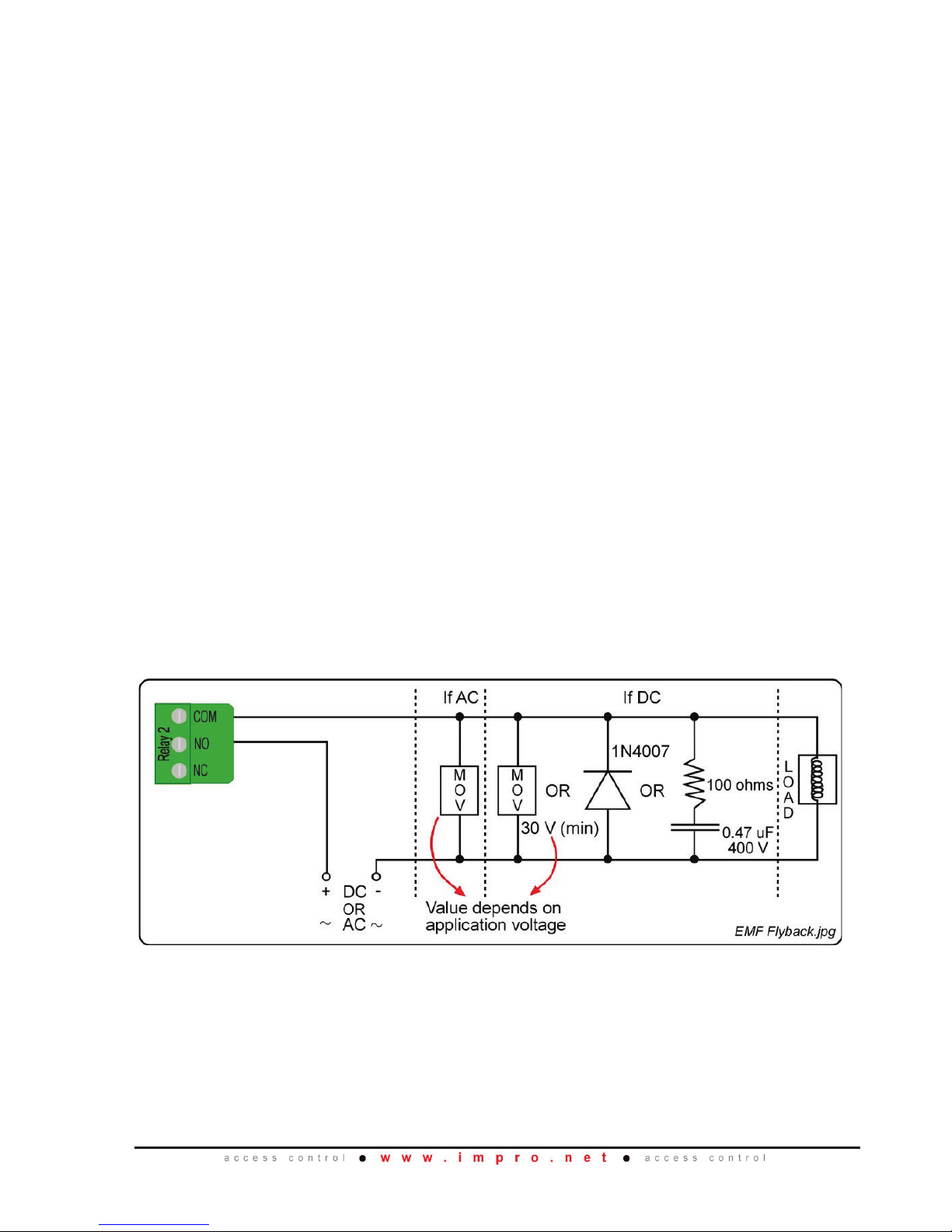
Arc Suppression
Snubber devices are recommended for EMF Flyback and Arc Suppression when
driving an inductive load with the Relay, see Figure 2.
Figure 2: EMF Flyback and Arc Suppression
HMW300-0-0-GB-00 October 2013 Page 6

Mounting the Impro (WRM) Wiegand Reader Module
CAUTION: Make certain that you mount the WRM on a vibration-free surface.
NOTE: The WRM can be mounted onto virtually any surface including metal.
NOTE: Cluster Modules are Hot-Swappable – it is not necessary to power them
down when adding, removing or wiring them up.
Clustering
Provided there are less than eight other Expansion Modules already clustered with the
Cluster Controller, you may add the WRM to an existing Cluster:
• Remove the Housing Cover from the WRM and plug the WRM into the Cluster
Socket on the right hand side of the Cluster Controller – or that of the
outermost Expansion Module in the cluster.
• Holding the WRM square against its neighbouring Module, mark the mounting
hole locations through the mounting holes in the back of the Housing Base.
• Remove the WRM, drill the mounting holes.
• Use the plastic Stand-Offs to provide space for cables behind the cluster, or if
the other modules in the Cluster are already mounted with stand-offs.
• Mount the WRM Housing Base firmly to the mounting surface using fasteners
(not included) appropriate for the mounting surface material.
• Select the gland plates that best suit the installation and/or knock out the
cable entry points as needed.
• Connect the reader cables, the digital inputs and the relay terminals as
necessary for the installation
• Commission the WRM (and its readers) via the menu options on the Access
Control Application.
• Replace the WRM Housing Cover and fasten closed with the two Allen head
screws provided.
Blank Space
HMW300-0-0-GB-00 October 2013 Page 7

Remote Mounting
When it is advantageous to mount a WRM near to the relevant door (and some
distance from the Cluster Controller), the WRM may be connected to the Cluster
Controller using an S-Bus cable up to a maximum of 150 m (490 ft.) long. The
procedure is as follows:
• Check to see how many other Device Addresses are already connected to the
S-Bus Host “D” Terminal of the Cluster Controller. No more than eight Device
Addresses should be connected to an S-Bus.
• Obtain a suitable Isolated DC Power supply to power the WRM and any
readers and magnetic locks, etc., that may be connected to the WRM.
• Remove the Housing Cover from the WRM and hold the module base in
position, mark the mounting hole locations through the mounting holes in the
back of the Housing Base.
• Remove the WRM, drill the mounting holes.
• Use the Stand-Offs to provide space for cables behind the module, if
necessary – or to allow for an uneven mounting surface.
• Mount the WRM Housing Base firmly to the mounting surface, using fasteners
(not included) appropriate for the mounting surface material.
• Select the gland plates that best suit the installation and/or knock out the
cable entry points as needed.
• Connect the reader cables, the digital inputs and the relay terminals as
necessary for the installation
• Commission the WRM (and its readers) via the menu options on the Access
Control Application.
• Replace the WRM Housing Cover and fasten closed with the two Allen head
screws provided.
DIP-switch Settings
NOTE: Whenever the DIP-switch settings are modified reset the Impro WRM to
acknowledge the new settings by disconnecting and reconnecting the power
supply to the WRM.
Reader 1 Select and Reader 2 Select DIP-switch Settings
Each of the Reader Ports has a 4-way DIP-switch to select the function of that Port.
NOTE: Where you have no Advanced Wiegand Reader (Impro Multi-discipline
Reader) connected, setting both Remote DIP-switches to the all off position
during an Auto-ID will not return any Fixed Addresses.
NOTE: When Wiegand and Multi Discipline Readers are used on the same
SYSTEM, all DIP Switches should take on the Wiegand settings.
HMW300-0-0-GB-00 October 2013 Page 8

DIP-switch Position
Connections
0
Advanced Wiegand Reader (Impro Multi-discipline
Readers). Full Tag codes and types.
1
No Remote attached, the Channel is used for Relay
and Digital Inputs only.
2
Impro Remote (including the Impro Multi-mode
Remote).
3
Impro RF 4-Channel Receiver or Impro (IR) Infrared
Receiver.
4
Magstripe.
5
Barcode (code 3 of 9) with Checksum.
6
Barcode (code 3 of 9) without Checksum.
7
Wiegand 26-bit, 44-bit, 40-bit, 37-bit and Tag + PIN-
code or Reason Code Mode.
(Sagem MA100, MA200, MA300 or Sagem J-Series).
8
Wiegand open format.
9
LEGACY UHF Receiver Support
If the UHF Receiver is connected, then Button 1 of
the Quad Transmitter reports.
10
LEGACY UHF Receiver Support
If the UHF Receiver is connected, then Button 2 of
the Quad Transmitter reports.
11
LEGACY UHF Receiver Support
If the UHF Receiver is connected, then Button 3 of
the Quad Transmitter reports.
12
LEGACY UHF Receiver Support
If the UHF Receiver is connected, then Button 4 of
the Quad Transmitter reports.
Table 1: Reader 1 Select and Reader 2 Select DIP-switch Settings
HMW300-0-0-GB-00 October 2013 Page 9

Wiegand Modes
Mode
Terminal Action
Tag Only
Treats all codes received as tag codes.
Tag + PIN
Treats the first Wiegand code received as the tag
code, and the second Wiegand code received as
the PIN-code.
Tag + Reason
Treats the first Wiegand code received as the tag
code, and the second Wiegand code received as
the Reason Code.
Tag + PIN + Reason
Treats the first Wiegand code received as the tag
code. The second and third Wiegand codes
received are treated as the PIN-code and Reason
Code respectively.
Table 2: Wiegand Modes
Wiegand Mode Rules
• Enter PIN-codes or Reason Codes on the Reader within 10 seconds otherwise the
tag code is discarded.
• The System allows 10 seconds each for the entry of the PIN-code and the Reason
Code in Tag + PIN + Reason Mode.
• If the Impro WRM expects a PIN-code and receives a number greater than 65535,
then the WRM assumes the number to be a tag code. The WRM discards the
previously read Tag for the current one and the WRM will still expect a PIN-code.
• If the Impro WRM expects a Reason Code and receives a number greater than
65535, then the WRM assumes the number to be a tag code. The WRM discards
the previously read Tag for the current one and the WRM will still expect a PINcode or Reason Code, depending on the mode.
• If the WRM expects a Reason code and instead receives a number in the range
100 to 65535, the WRM assumes this is an error. The WRM discards the entire
transaction, entering a new tag code starts the process again.
• If using PIN-codes and Reason Codes set the Impro WRM switches for Wiegand
26-bit, 37-bit, 40-bit and 44-bit, not Wiegand open format.
Blank Space
HMW300-0-0-GB-00 October 2013 Page 10

ELECTRICAL CONNECTIONS
Key Component Positions
Figure 3: Impro WRM Key Component Positions
HMW300-0-0-GB-00 October 2013 Page 11

Connecting Multi Discipline Readers
Figure 4 shows a typical electrical connection diagram for the “clustered” Impro WRM.
Figure 4: Typical Clustered Impro WRM Electrical Connections
NOTE: * Refer to Figure 2 for Arc Suppression details.
NOTE: The ideal cable distance between the Impro WRM and its Multi-discipline
Reader MUST NOT exceed 150 m (164 yd).
NOTE: This diagram shows typical connections to the Impro WRM 190.
Connections remain the same for all models of the Impro WRM.
NOTE: Connection details remain the same for all Multi-discipline Reader models.
HMW300-0-0-GB-00 October 2013 Page 12

Connecting to Wiegand Readers
Figure 5: Connecting Impro WRM to Wiegand Reader
NOTE: When connecting the Wiegand Keypad Mullion Reader (WKM900) or the
Wiegand Junction Box Reader (WJB900), use the cable colours displayed in
brackets.
NOTE: Connection details remain the same for all Wiegand models.
NOTE: Use the connections shown here, when connecting a Sagem MA100,
MA200, MA300 or MA500 or Magstripe Reader to the Impro WRM.
HMW300-0-0-GB-00 October 2013 Page 13

Connecting to a Multi-mode Remote
Figure 6: Impro WRM Connected to a Multi-mode Remote
NOTE: Connection details remain the same for all Multi-mode Remote models.
NOTE: The cable distance between the Impro WRM and its Multi-mode Remote
MUST NOT exceed 10 m (33 ft).
HMW300-0-0-GB-00 October 2013 Page 14

Connecting other Devices
Figure 7: Connecting other Devices to the WRM
HMW300-0-0-GB-00 October 2013 Page 15

S-Bus and Power Wiring for Remote Installation
Figure 8 shows how to power the Impro WRM and its relay-driven loads in an
“unclustered”, remote installation position.
Figure 8: Typical S-Bus and Power Wiring for Remote Installation
NOTE: The wiring of the RTE, DOS and Reader Terminals remains the same as shown
on pages 12 to 14.
HMW300-0-0-GB-00 October 2013 Page 16

Power-on Self-test
The Power-on Self-test tests the RAM and Flash Checksums.
If any parameter in the Module Self-test fails, the connected Readers will emit a
continuous beep for 2 seconds before the 2 short start-up beeps.
When the Terminal passes the Self-test, any Readers attached will emits two short
beeps, each 200 ms in duration, separated by a 200 ms inter-beep pause.
WRM Address Information
Each Impro (WRM) Wiegand Reader Module is, in fact, two Reader Interfaces in one.
The first Fixed Address is associated with Reader [1], and the second with Reader [2].
Each WRM is allocated two unique Fixed Addresses at the factory. These addresses
are stored in the WRM’s memory.
NOTE: If set to MDR mode (all dip switches off) and no MDR is connected to one
channel, the fixed address for the un-used channel will be hidden. In all
other instances both addresses on the WRM are always shown.
Fixed Address Label
Once the Impro WRM is installed, sketch a rough site plan. Attach the loose (additional
Fixed Address Label packaged with the WRM) Fixed Address Label in the position of
the Terminal on the sketched site plan. When the system installation is complete and
all the units are represented on the site plan by their Fixed Address Labels, file the site
plan for future reference.
GUARANTEE OR WARRANTY
CAUTION: We reserve the right to nullify the product’s guarantee or warranty
where you have not properly installed the Metal-oxide Varistors.
This product conforms to our Guarantee or Warranty details placed on our Web Site, to
read further please go to www.impro.net
.
USER NOTES
HMW300-0-0-GB-00 October 2013 Page 17

USER NOTES
HMW300-0-0-GB-00 October 2013 Page 18

USER NOTES
HMW300-0-0-GB-00 October 2013 Page 19

This manual is applicable to the Impro (WRM) Wiegand Reader Module,
HMW700-0-0-GB-01, and HMW701-0-0-GB-00
(The last two digits of the Impro stock code indicate the issue status of the product.)
HMW300-0-0-GB-00 Issue 01
October
2013
Impro\Access Portal\WRM Wiegand Reader
Module\English Manuals\LATEST ISSUE\
conwrm-insm-en-01.docx
HMW300-0-0-GB-00 October 2013 Page 20
 Loading...