

Page 1

MODEL NUMBERS: HRR900-0-1-GB-XX
HRR901-0-1-GB-XX
Quad Receiver
433.92 MHz 4-Channel RF Receiver
INSTALLATION MANUAL
SPECIFICATIONS
Working Environment
Water resistance ....................
Designed to work in an indoor or outdoor
environment similar to IP44, the Impro Quad
Receiver is water resistant
Power Source
Input Voltage ................................
11V to 15 V DC (Polarity sensitive)
Power Requirements
Current (mA)
Power (W)
12 V DC .................................
60
0.7
NOTE: When upgrading or replacing a legacy “ImproX UHF Receiver”, make sure
to reconnect using a 12V DC supply.
INSTALLATION INFORMATION
CAUTION: These two models of the Impro Quad Receiver only support
connection to the Impro IXP220 Controller, IXP20 Controller, iTRT
(Intelligent Twin Reader Terminal), MfT (Multi-function Terminal), TA
(Time Attendance Terminal), and the Impro UniScan and FlexiScan
Controllers. DO NOT attempt to connect this Receiver to an Impro
(DT) Door Terminal.
Page 2
Accessories
Find the following when unpacking the Quad Receiver:
• The Quad Receiver consists of a glass-filled nylon Base with the PCB attached by
four screws, a glass-filled nylon Top Cover (press-down firmly to clip into the
base).
• A black gland plate for power, data and RF (in the case of the HRR901) lines into
the unit (this needs to be drilled to accommodate the wiring during installation).
• An extra Serial Number Label.
General
Impro TA Terminal Considerations
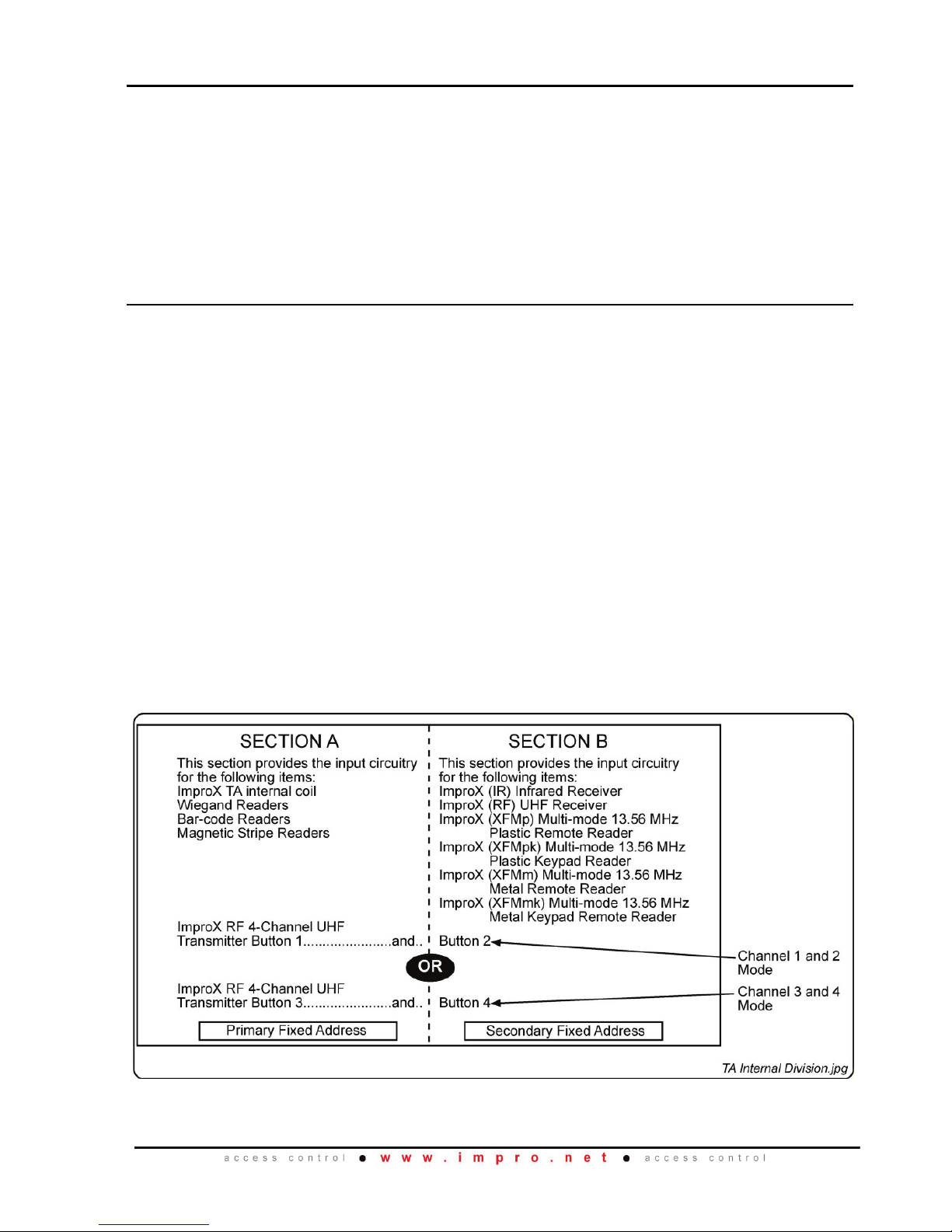
When installed with the Impro TA, the Terminal can be placed in one of two modes:
Channel 1 and 2 Mode or Channel 3 and 4 Mode. If you place the Terminal in Channel
1 and 2 Mode then Channels 1 and 2 of the Impro Quad Transmitter (TRK900-1-1-GBXX) are processed. Channel 1 is processed as the Terminal’s Primary Fixed Address
and Channel 2 is processed as the Terminal’s Secondary Fixed Address. This
scenario also applies to Channel 3 and 4 Mode. Using the Impro TA as an example,
refer to Figure 1 for clarification.
Upgrading or replacing legacy UHF Receiver
When upgrading from or replacing a legacy UHF receiver, it is important to do the
following:
• Change the DC supply voltage from 5V to 12V (12V is available on IXP220, IXP20
or iTRT)
• When connecting to an IXP220, IXP20, iTRT, Mft or TA, ensure that the “Legacy”
link is in place. (There is no need to change any DIP Switch settings.)
Figure 1: TA Internal Division Showing Channel 1 and 2 Mode and
Channel 3 and 4 Mode
HRR300-0-0-GB-01 April 2013 Page 2
Page 3

Maximum Data Communications Distance
The maximum cable length between the Impro Quad Receiver and the Terminal or
Controller is 150 m (164 yd.), using a good quality multi core cable. The cross-sectional
area of the cable conductors must be at least 0.21mm
2
(24 AWG) for each of the “-“, “+”
and “D” conductors. To mitigate interference, cables should be a screened multi core
cable.
Solder a 2.5 mm
2
(13 AWG) grounding wire to the Host end of the screen drain wire
(insulate the soldered joint so that it is not left exposed) and route this wire to the
nearest Electrical Mains EARTH terminal – most often this may be same power socket
used by the DC Power supply for the Controller.
NOTE: The Quad Receiver (Device) end of the screen drain wire must not be
connected to anything.
Serial Number Label
The loose Serial Number Label (packaged with the Receiver) identifies the model of
Receiver and its Serial Number.
Installation Considerations for Best Performance
When installing the HRR900-0-1-GB-XX, it is important to consider the location and
environment for achieving optimum performance.
Location
Mounting the Impro Quad Receiver or Antenna mid-distance between the expected
point of entry and exit may balance the available operational range between both
locations.
Line-of-Sight
Locating the Impro Quad Receiver or Antenna within line-of-sight of the expected point
of entry and exit may result in greater received signal strength, increasing the
operational range.
Integrated Antenna (HRR900-0-1-GB-XX)
Mounting this Impro Quad Receiver on (or close to) conductive, ferrous materials,
damp surfaces (i.e.: walls) or electrical equipment can affect the overall performance of
the Impro Quad Receiver by either blocking, absorbing or interfering with the
transmitted signal from the Quad Transmitter.
Due to the radiation pattern of the integral antenna, it is preferable to install the Impro
Quad Receiver in a high position, with its integrated antenna pointing down. If this is
not possible, then consider using the HRR901-0-1-GB-XX with an external antenna that
meets the requirements of the installation.
HRR300-0-0-GB-01 April 2013 Page 3
Page 4

External Antenna (HRR901-0-1-GB-XX)
This model is recommended when an installation calls for special antenna
considerations. This Impro Quad Receiver has its internal antenna bypassed and is
configured for direct connection to any of the various suitable antenna types available
(i.e.: high gain, Omni-directional, yogi etc.). An appropriate antenna must be selected
by the installer to complete the installation.
External Antenna Basic Requirements
Frequency ..............................
433.92 MHz
Impedance .............................
50 Ω
Connector ..............................
SMA Male (Straight preferred)
Transmit-Receive (Reciprocity) Trouble Shooting:
The Impro Quad Receiver has a built-in LED RSSI (Received Signal Strength Indicator)
bar graph. Before permanently mounting the Quad Receiver (or the external antenna
for HRR901) to a surface, it is recommended that the RSSI is checked with the
receiving antenna temporarily held in its proposed mounting position, and the Impro
Quad Transmitter at the expected point of entry or exit.
RSSI (Received Signal Strength Indication)
Strong .......
Installation is perfect, no need to change anything
Average .....
Installation is good enough for nominal operation
Weak
.........
Consider installing the Quad Receiver in another location to
improve operation
No Signal ..
There is no reception at the current location. Refer to all of the
above installation considerations or check the installation for faults
Figure 2: Radiation Pattern for the HRR900’s integrated antenna
In Figure 2, the 3-D isometric radiation pattern (extreme right) is achieved with the
HRR900 Impro Quad Receiver mounted flat against the wall, right near the top, with the
internal antenna facing downwards. The green volume represents the direction of
maximum sensitivity.
HRR300-0-0-GB-01 April 2013 Page 4
Page 5

Four Channel Operation
When using the Impro Quad Receiver and a single Impro (iTRT) Intelligent Twin
Reader Terminal (XRT910-0-0-GB-XX, XRT920-0-0-GB-XX, IPS920-0-0-GB-XX or
IPS921-0-0-GB-XX), only two Push-buttons on the Impro Quad Transmitter (TRK900-11-GB) are available for use.
To use all four of the Quad Transmitter’s Push-buttons, connect two Impro (iTRT)
Intelligent Twin Reader Terminals (XRT910-0-0-GB-XX, XRT920-0-0-GB-XX, IPS9200-0-GB-XX or IPS921-0-0-GB-XX), to the Quad Receiver, see Figure 3.
Figure 3: Using Four Channels
Impro FlexiScan Controller
When using the Quad Receiver with the FlexiScan Controller (HCM991-0-0-GB-XX),
EACH of the four Quad Transmitter buttons (when “added” to the Tag Database) are
mapped to each the FlexiScan’s four relays respectively. The “Legacy link” must be
REMOVED from the Quad Receiver PCB. See Figure 9 for wiring details
Impro UniScan Controller
When using the Quad Receiver with the UniScan Controller (HCM990-0-0-GB-XX), all
four Quad Transmitter buttons will trigger the UniScan's single relay ONLY with the
Quad Transmitter buttons that have been “added” or "enrolled”. The “Legacy link” must
be REMOVED from the Quad Receiver PCB when connected to a UniScan Controller.
See Figure 10 for wiring details.
HRR300-0-0-GB-01 April 2013 Page 5
Page 6

Cable Gland Plate Drilling Procedure:
• Remove the Housing Cover ensuring that the Gland Plate remains in its
position in the slot in the base of the housing.
• Make a mark on the Gland Plate corresponding exit points that will have the
wires run NEXT to, and NOT OVER the Impro Quad Receiver PCB (if using
the built-in antenna, this area must be kept cleared of any objects).
• Remove the Gland Plate and drill a 2mm pilot hole through the mark/s.
• Select a drill size for a snug fit around the cable/s to be used and drill the
hole/s to the final size/s required.
Mounting the Impro Quad Receiver
CAUTION: Make certain that you mount the Impro Quad Receiver on a
vibration-free surface.
Select the mounting position of the Impro Quad Receiver, considering accessibility and
routing of wires – and test to ensure the RSSI reading is adequate. (See TransmitReceive (Reciprocity) Trouble Shooting on page 4.)
Secure the housing to a vertical mounting surface, using suitable screws and wall
plugs, nuts and bolts, rivets or double-sided adhesive tape.
HRR300-0-0-GB-01 April 2013 Page 6
Page 7
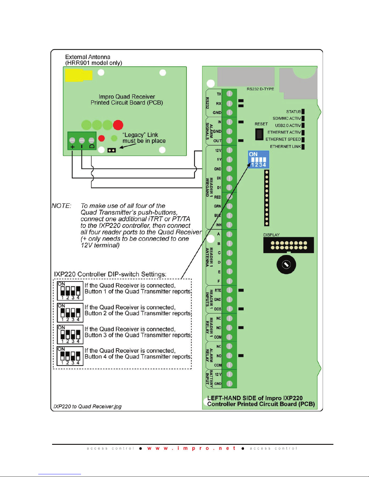
Connecting the Impro Quad Receiver
Figure 4 to 10 show typical electrical connection diagrams for the Receiver.
Figure 4: Impro Quad Receiver Connected to the IXP220 Controller
HRR300-0-0-GB-01 April 2013 Page 7
Page 8
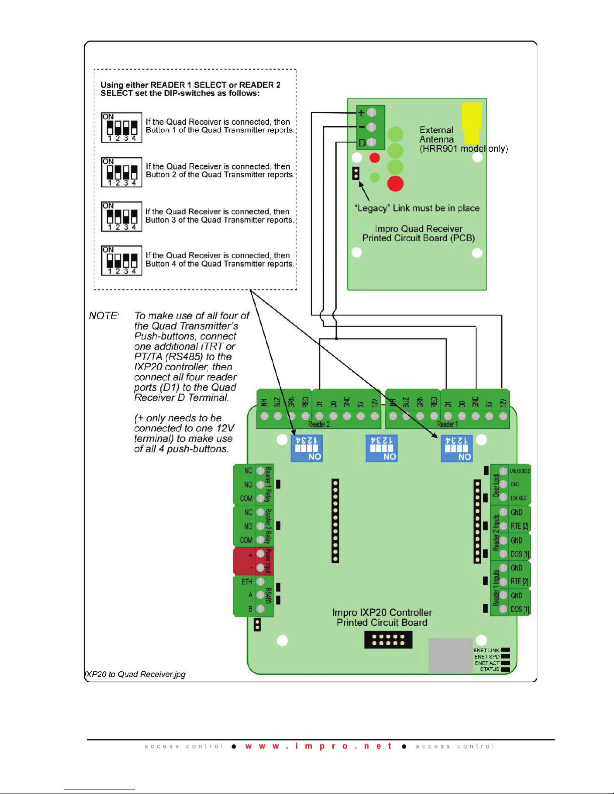
Figure 5: Impro Quad Receiver Connected to the IXP20 Controller
HRR300-0-0-GB-01 April 2013 Page 8
Page 9
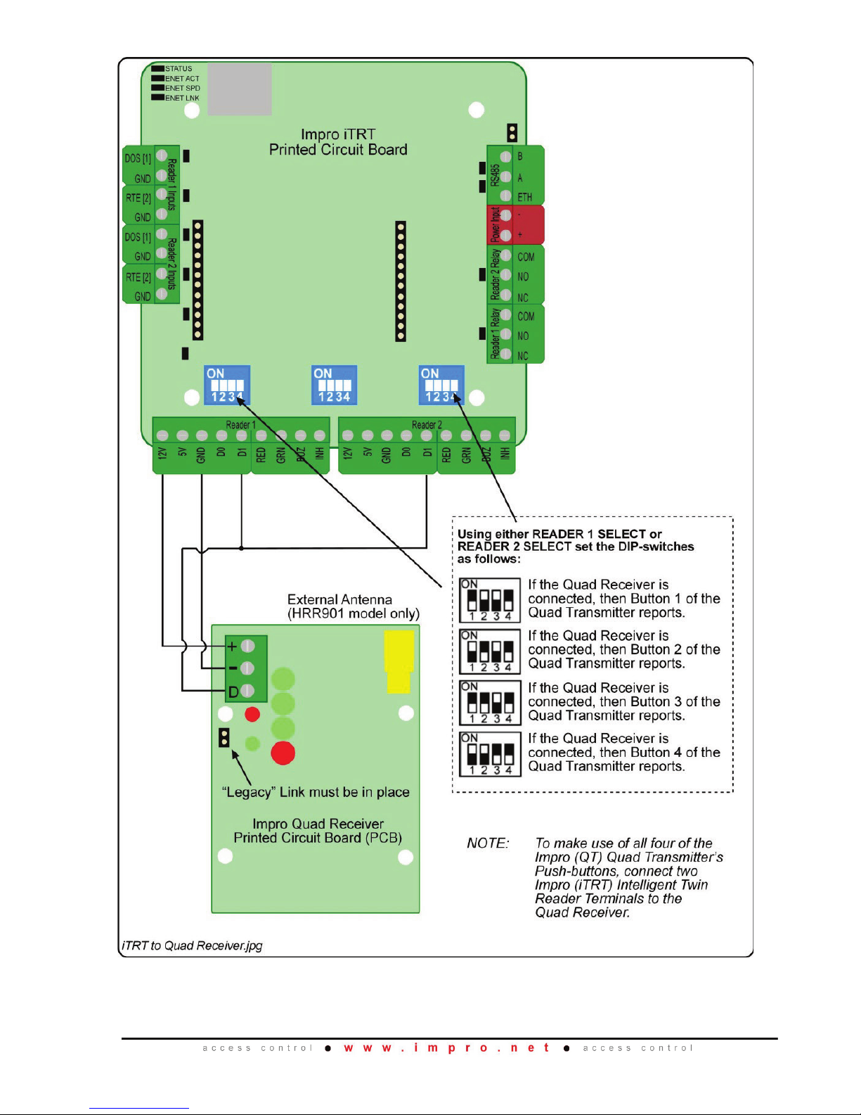
Figure 6: Impro Quad Receiver Connected to the Impro iTRT
HRR300-0-0-GB-01 April 2013 Page 9
Page 10
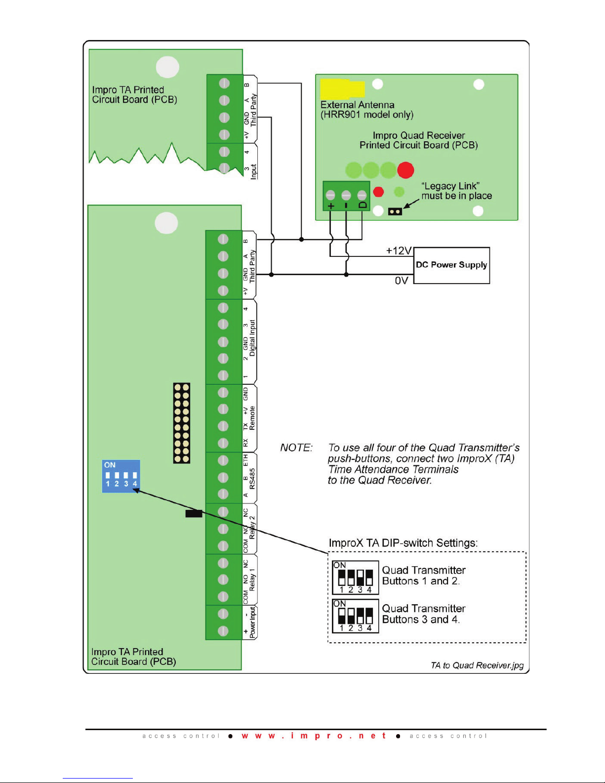
Figure 7: Impro Quad Receiver Connected to two Impro PT/TA Terminals
HRR300-0-0-GB-01 April 2013 Page 10
Page 11
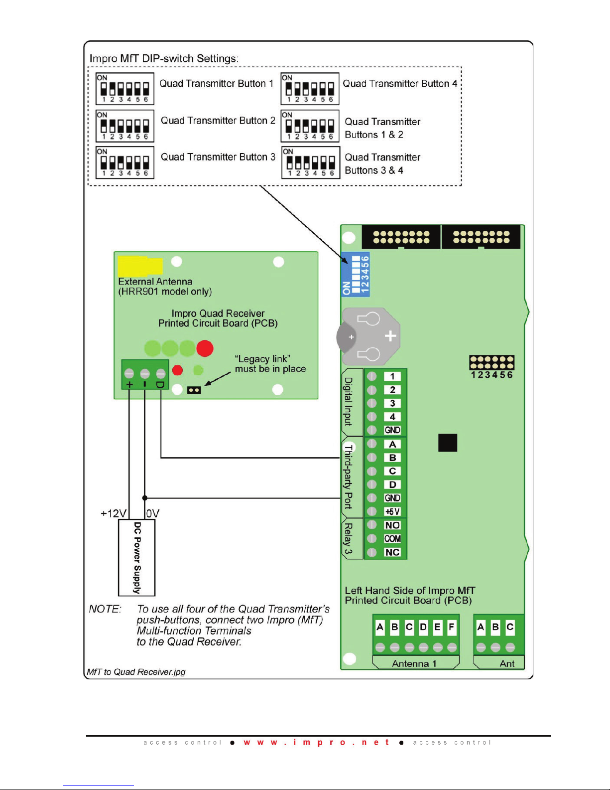
Figure 8: Impro Quad Receiver Connected to the Impro MfT
HRR300-0-0-GB-01 April 2013 Page 11
Page 12
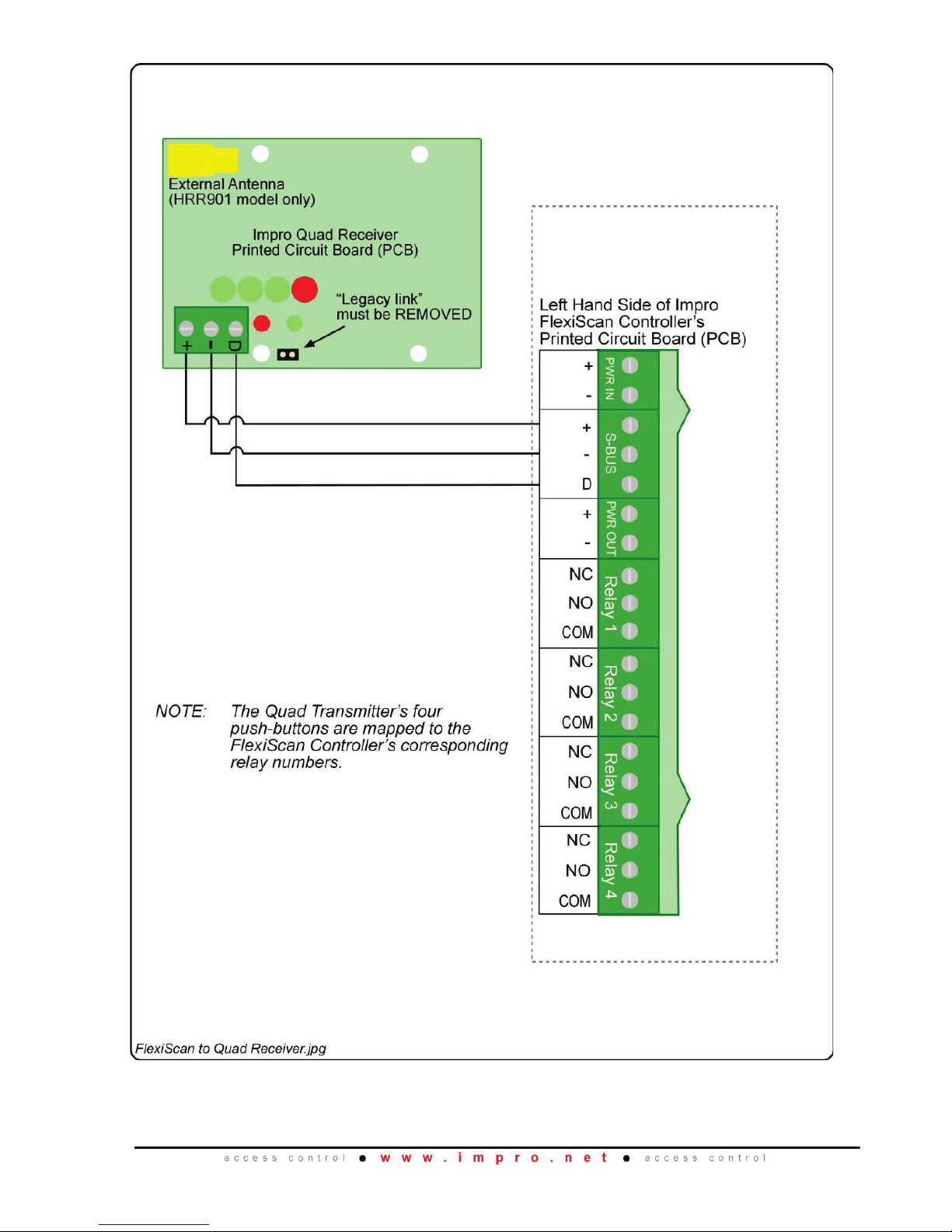
Figure 9: Impro Quad Receiver Connected to the Impro FlexiScan Controller
HRR300-0-0-GB-01 April 2013 Page 12
Page 13
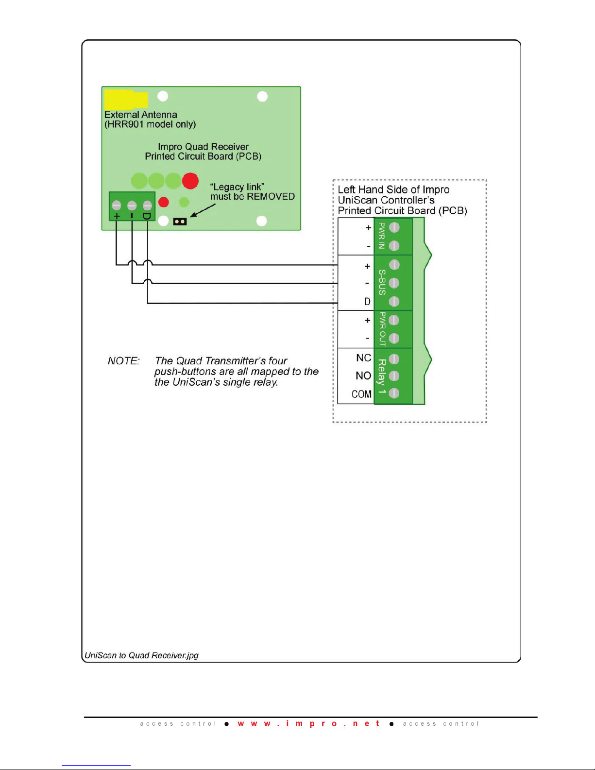
Figure 10: Impro Quad Receiver Connected to the Impro UniScan Controller
HRR300-0-0-GB-01 April 2013 Page 13
Page 14

GUARANTEE OR WARRANTY
This product conforms to our Guarantee or Warranty details placed on our Web Site, to
read further please go to www.impro.net
.
User Notes
HRR300-0-0-GB-01 April 2013 Page 14
Page 15

User Notes
HRR300-0-0-GB-01 April 2013 Page 15
Page 16

This manual is applicable to both variants of the Impro Quad Receiver,
HRR900-0-1-GB-XX and HRR901-0-1-GB-XX.
(The last two digits of the Impro stock code indicate the issue status of the product).
HRR300-0-1-GB-01 Issue 2
April
2013
Impro QR\English Manuals\LATEST ISSUE\Quad
Rec-insm-en-02.docx
s
HRR300-0-0-GB-01 April 2013 Page 16
 Loading...