

ISTRUZIONI PER L’INSTALLAZIONE
INSTALLATION INSTRUCTIONS
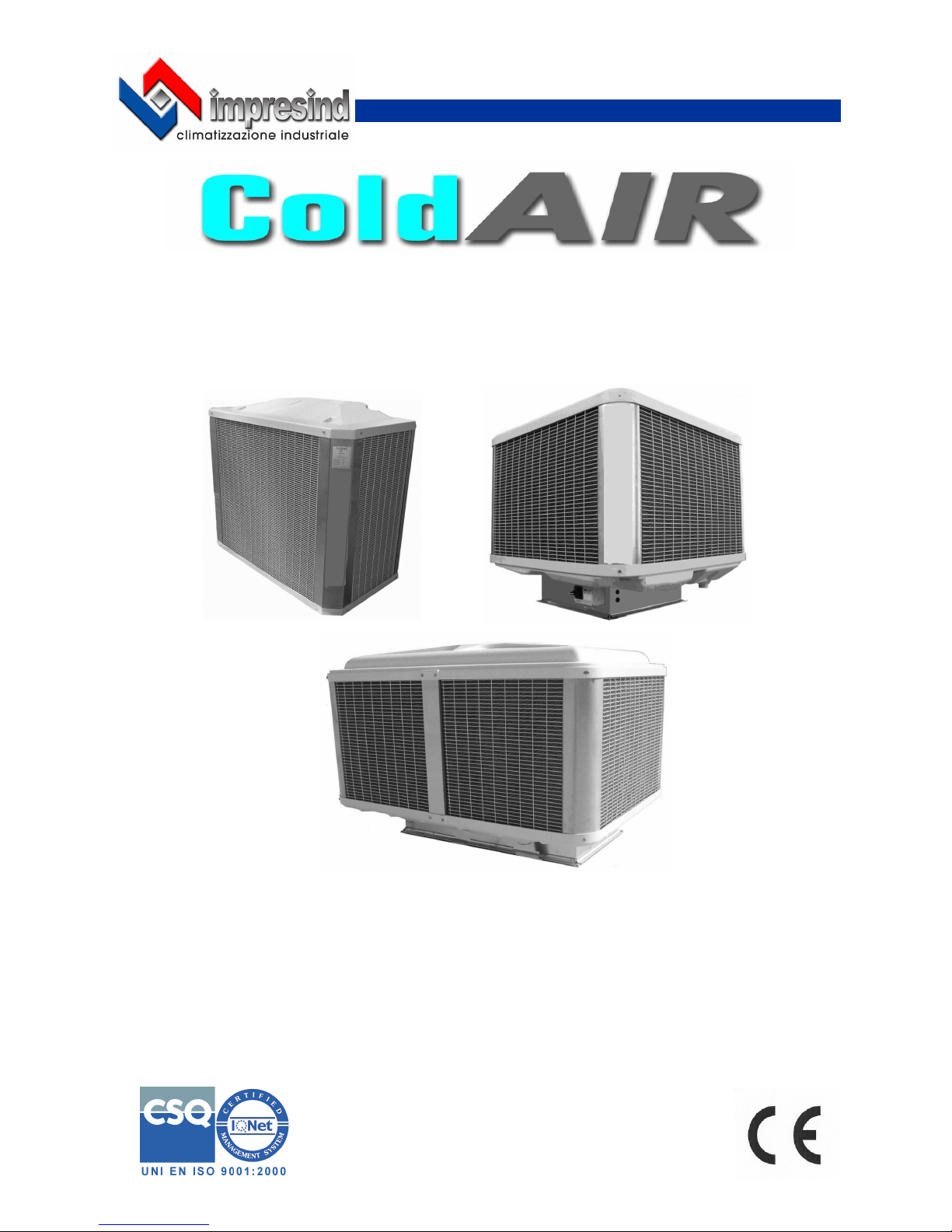
RAFFRESCATORI EVAPORATIVI ADIABATICI
ADIABATIC EVAPORATIVE COOLERS
ISTR-INST-CA18 Ed.01-2018
IT
INDICE
INFORMAZIONI GENERALI ............................................................................................................................. 3
Premessa ........................................................................................................................................................ 3
SEZIONE 1 – CARATTERISTICHE .................................................................................................................. 4
1.1 Presentazione del Raffrescatore Evaporativo ColdAir ............................................................................. 4
1.2 Uso previsto .............................................................................................................................................. 4
1.3 Dati identificativi della macchina ............................................................................................................... 5
1.4 Quadri elettrici ........................................................................................................................................... 5
SEZIONE 2 – TRASPORTO, MOVIMENTAZIONE, DISIMBALLAGGIO, IMMAGAZZINAMENTO ............... 5
2.1 Ricevimento materiale .............................................................................................................................. 5
2.2 Trasporto, movimentazione e sollevamento ............................................................................................. 5
2.2.1 Sollevamento con carrello elevatore ..................................................................................................... 5
2.2.2 Sollevamento con funi ........................................................................................................................... 6
2.3 Disimballaggio .......................................................................................................................................... 6
2.4 Immagazzinamento .................................................................................................................................. 6
SEZIONE 3 – POSIZIONAMENTO e INSTALLAZIONE ................................................................................... 7
3.1 Avvertenze generali ................................................................................................................................. 7
3.2 Installazione a tetto ................................................................................................................................... 7
3.2.1 Raffrescatori evaporativi serie TA ......................................................................................................... 7
3.2.2 Raffrescatori evaporativi serie TC ......................................................................................................... 8
3.3 Installazione a parete/finestra ................................................................................................................... 9
3.3.1 Raffrescatori evaporativi serie TA ......................................................................................................... 9
3.3.2 Raffrescatori evaporativi serie TC ......................................................................................................... 9
3.3.3 Raffrescatori evaporativi serie TA & TC versione “SD” ...................................................................... 10
3.3.4 Raffrescatori evaporativi serie FPA ..................................................................................................... 11
3.3.4.1 Installazione a parete ............................................................................................................................ 11
3.3.4.2 Installazione a finestra ........................................................................................................................... 11
3.4 Note a completamento ............................................................................................................................ 12
3.5 Allacciamento alla rete elettrica .............................................................................................................. 12
3.6 Allacciamento alla rete idrica .................................................................................................................. 13
SEZIONE 4 – SISTEMI DI PROTEZIONE ....................................................................................................... 13
4.1 Dispositivi di protezione .......................................................................................................................... 13
4.2 Segnaletica applicata a bordo macchina ................................................................................................ 13
4.3 Abbigliamento ......................................................................................................................................... 13
4.4 Rischi residui .......................................................................................................................................... 14
4.5 Situazioni di emergenza ......................................................................................................................... 14
SEZIONE 5 – NOTE SUL FUNZIONAMENTO ................................................................................................ 14
DISEGNI DIMENSIONALI .................................................................................................................... 15-16-17
SCHEMI DI COLLEGAMENT0 ELETTRICO .............................................................................................18-19
CARATTERISTICHE TECNICHE ...............................................................................................................20-21
2

INFORMAZION I GENERALI
PREMESSA
Gentile Cliente,
Nel ringraziarLa per aver scelto un prodotto Impresind S.r.l. La informiamo che:
• il contenuto di questo documento ha solo scopo informativo ed è soggetto a modifiche senza
preavviso;
• il presente manuale non può essere né parzialmente né interamente riprodotto, trasmesso, tra-
scritto o memorizzato in un sistema di archiviazione in alcuna forma o in alcun mezzo, sia esso meccanico, magnetico, ottico, chimico o altro, senza l’autorizzazione scritta di Impresind S.r.l.
Gli addetti all’installazione devono obbligatoriamente conoscere il contenuto del presente manuale
prima dell’installazione e della messa in servizio della macchina.
In caso di smarrimento o danneggiamento del presente manuale, richiederne immediatamente una
copia contattando il Servizio Assistenza Tecnica della Impresind Srl, citando i dati identificativi
dell’impianto riportati sulle targhe dati.
La macchina è conforme alle seguenti direttive comunitarie:
2006/42/CE Direttiva Macchine
2014/35/UE Direttiva Bassa Tensione
2014/30/UE Direttiva sulla Compatibilità Elettromagnetica
2009/125/UE Direttiva sulla Progettazione Ecocompatibile
IT
3
IT
SEZIONE 1 – CARATTERISTICHE
1.1 Presentazione del Raffrescatore Evaporativo ColdAir
Per migliorare il microclima estivo all’interno di un locale produttivo, commerciale o altro occorre ventilare l’ambiente con molti ricambi d’aria nuova e filtrata, possibilmente raffreddata. Nel caso di grandi
locali, ad esempio quelli industriali, un impianto di condizionamento spesso non è consigliabile in
quanto, a causa del grande volume d’aria da raffreddare e dei carichi termici di processo da neutralizzare, la quantità di energia necessaria è elevatissima e l’effetto di raffreddamento viene ridotto dagli
impianti di estrazione dell’aria esausta e dalla frequente apertura dei portoni per lo svolgimento
dell’attività.
Un’ottima soluzione è rappresentata da un impianto di raffrescatori evaporativi che raffreddano l’aria
con un principio naturale: l’aria passa attraverso speciali filtri bagnati d’acqua, cede parte del suo calore durante il processo di evaporazione dell’acqua ed abbassa la sua temperatura. L’assenza di
macchine frigorifere riduce al minimo i consumi di energia e consente di trattare grandi volumi d’aria
per i molti ricambi necessari.
1.2 Uso previsto
Il raffrescatore evaporativo Cold Air può essere installato in tutti gli ambienti dove è necessario un
miglioramento del microclima, dove occorre ventilare l’ambiente con molti ricambi d’aria nuova e filtrata, possibilmente raffrescata, come :
• locali produttivi e artigianali
• locali commerciali e magazzini
• locali sportivi in genere
E’ assolutamente vietato modificare la macchina e la sua destinazione d’uso
La Impresind Srl declina ogni responsabilità per eventuali danni che potrebbero, direttamente
o indirettamente, derivare da persone esposte o cose, in conseguenza di uso improprio da
quello per cui è stata concepita la macchina, installazione non corretta, alimentazioni non appropriate, ambienti di installazione modificati o diversi da quelli comunicati in fase di conferma d’ordine, gravi carenze nella manutenzione, interventi e modifiche non autorizzati, utilizzo
di ricambi non originali, rimozione delle protezioni attive e passive, inosservanza delle istruzioni per l’uso, negligenza, ecc.
NON è consentito per nessuna ragione utilizzare la macchina per scopi differenti da quelli per
cui è stata progettata, né utilizzarla con modalità differenti da quelle riportate nel presente manuale.
NON installare la macchina in locali chiusi, l’installazione della stessa dovrà avvenire all’esterno dei locali da trattare, salvo esplicita approvazione del costruttore .
NON sovrapporre alcun peso sulla macchina
NON mettere in funzione la macchina se non e’ collegata al relativo impianto ( canale ) di distribuzione aria.
Durante il funzionamento dell’impianto non toccare il ventilatore - Pericolo meccanico .
E’ vietato operare su parti in movimento
E’ assolutamente vietato installare i raffrescatori evaporativi Cold AIR in ambienti con pericolo d’esplosione.
4
1.3 Dati identificativi della macchina
I dati identificativi della macchina sono riportati sulla scheda di garanzia fornita al cliente in allegato al
resto della documentazione e sulla targhetta identificativa presente sulla macchina stessa.
In caso di richiesta di Assistenza Tecnica o di parti di ricambio, citare sempre il modello ed il
numero di matricola della macchina.
IT
5
1.4 Quadri elettrici
I quadri elettrici , eventualmente forniti dalla Impresind s.r.l. sono realizzati in conformità alla norma
EN 60204/1:2016
E’ assolutamente vietato modificare i quadri elettrici
SEZIONE 2 – TRASPORTO, MOVIMENTAZIONE, DISIMBALLAGGIO, IMMAGAZZINAMENTO
2.2 Trasporto, movimentazione e sollevamento
Verificare gli imballi ed il loro contenuto, nel caso si riscontrassero danni dovuti al trasporto,
apporre riserva di danno sul documento di spedizione controfirmato dal vettore e successivamente inviarne una copia via fax o via mail (impresind@impresind.it) alla Impresind Srl.
Prestare attenzione nel maneggiare i Raffrescatori Evaporativi durante le fasi di scarico dal
mezzo di trasporto, la movimentazione ed il posizionamento, per evitare danni all’apparecchio. Evitare il contatto con elementi che potrebbero danneggiare l’apparecchio.
La IMPRESIND s.r.l. declina ogni responsabilità per danneggiamenti arrecati ai Raffrescatori
Evaporativi dovuti a trasporto, carico e scarico mal eseguiti o a mancanza di protezione dagli
agenti atmosferici.
2.1 Ricevimento materiale
Alla consegna della fornitura presso il cliente è indispensabile verificare lo stato di integrità della merce.
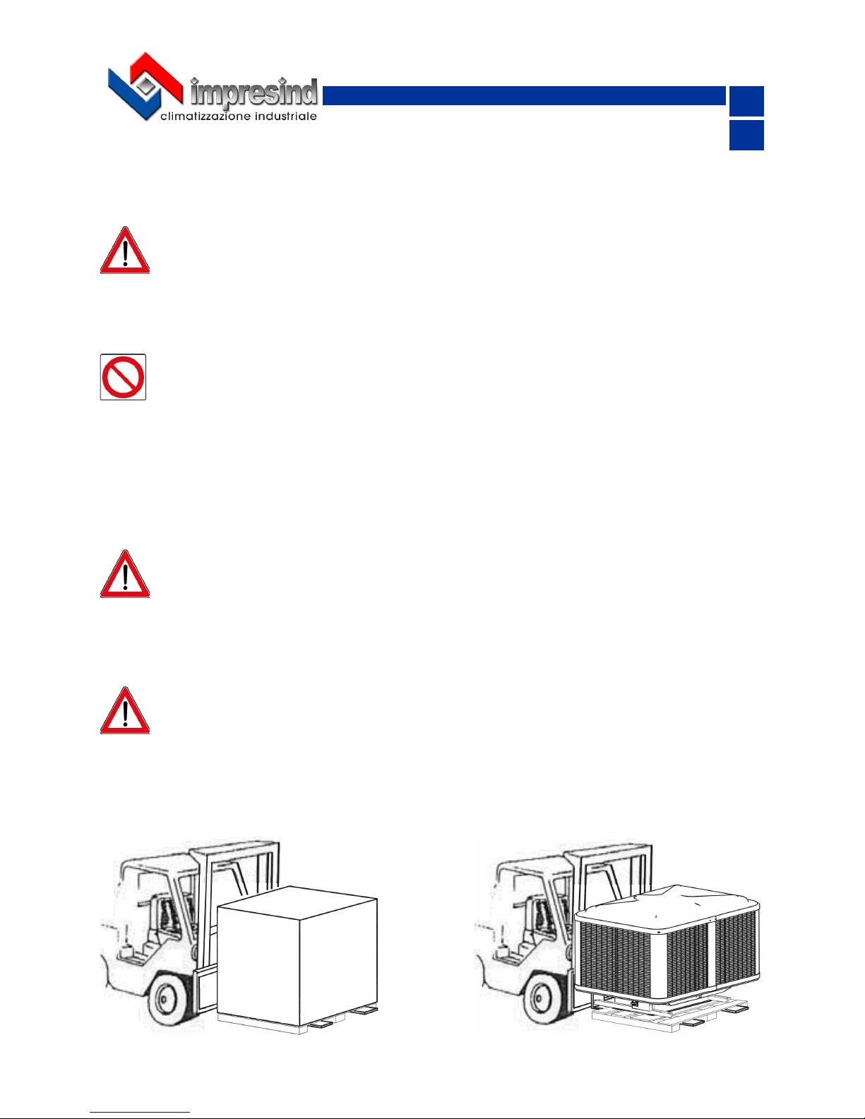
2.2.1 Sollevamento con carrello elevatore
Allargare le forche in modo da equilibrare il carico
IT
6
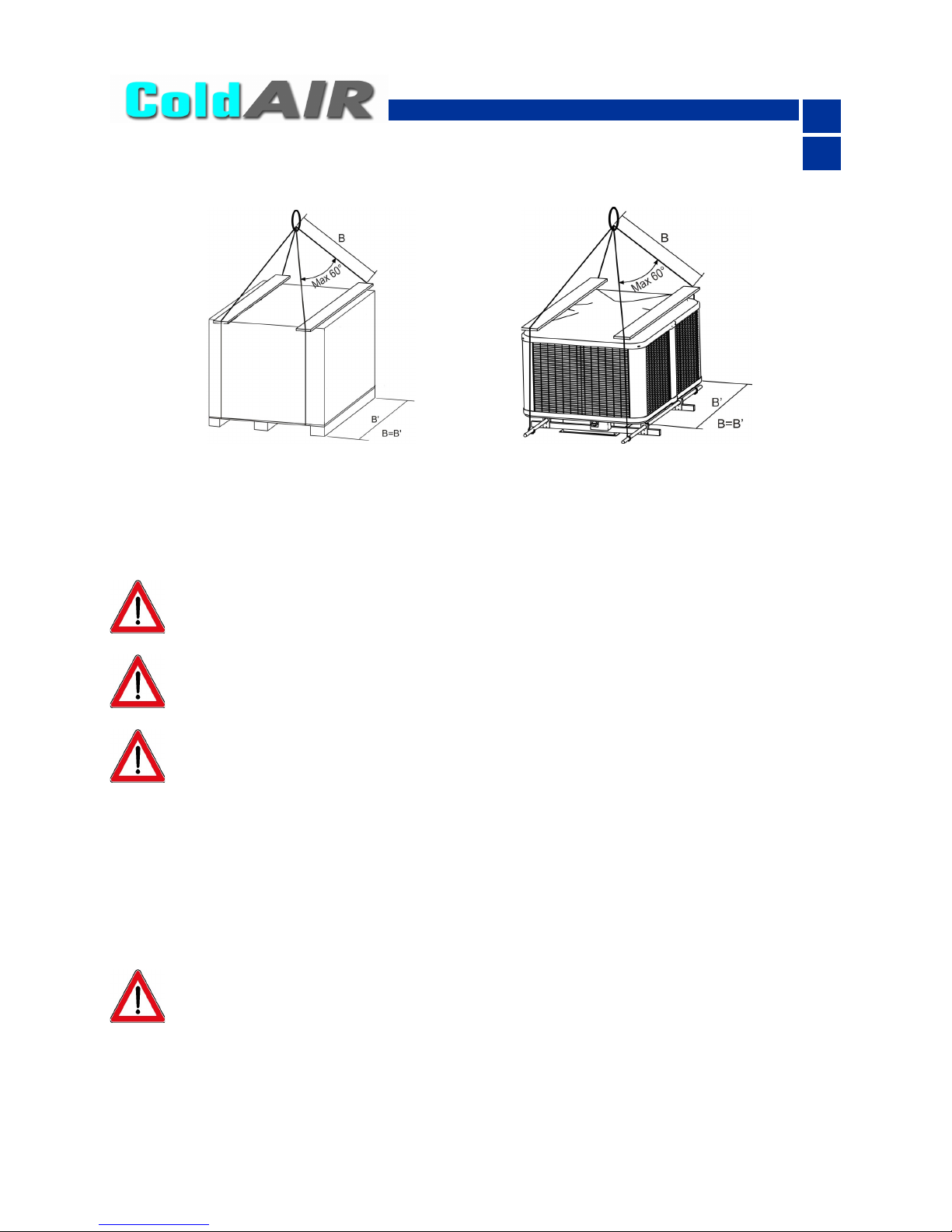
2.2.2 Sollevamento con funi
E’ vivamente consigliato applicare le funi come indicato in figura, interponendo distanziali di lunghezza adeguata per impedire che le funi stringendosi non danneggino l’involucro.
Dato il notevole peso, i modelli della serie TC ed i modelli in versione “SD” sono stati dotati di fori
passanti opportunamente posizionati per l’introduzione di tubi che consentono il sollevamento con
funi anche quando privi di imballo.
Appoggiare con prudenza la merce in modo da evitarne bruschi spostamenti o, peggio, cadute.
2.3 Disimballaggio
E’ ASSOLUTAMENTE VIETATO sostare sotto i carichi sospesi ed all’interno del raggio di
azione del mezzo di sollevamento .
Per la movimentazione utilizzare, in funzione del peso, mezzi adeguati come previsto dalla
direttiva 89/391/CEE e successive modifiche
Far effettuare il sollevamento solo da personale qualificato.
Liberare dall’imballo tutti i componenti avvolti o racchiusi nello stesso e raccoglierli in modo da prevenire potenziali pericoli di incendio e soffocamento di persone o animali.
Lasciare l’apparecchio appoggiato sul proprio imballo di trasporto con le eventuali protezioni in modo
che la parte inferiore rimanga sollevata e non venga danneggiata sino a quando verrà installata sui
dispositivi previsti.
Lo smaltimento dei materiali di imballaggio deve avvenire in conformità alle normative vigenti
nel Paese di destinazione dei Raffrescatori Evaporativi.
2.4 Immagazzinamento
Durante il trasporto e l’immagazzinamento assicurarsi che la temperatura ambiente sia compresa tra
-10 e 50 °C.
Qualora i raffrescatori evaporativi Cold Air debbano essere immagazzinati, assicurarsi che l’umidità
relativa del magazzino sia compresa tra il 5% ed il 90%.
IT
7
SEZIONE 3 – POSIZIONAMENTO E INSTALLAZIONE
3.1 Avvertenze generali
Prima di procedere all’installazione assicurarsi che ogni raffrescatore evaporativo sia stato disimballato e ne sia stata verificata l’integrità di tutti i suoi componenti.
La messa in opera e l’installazione dei raffrescatori evaporativi sono operazioni che possono compromettere il buon funzionamento dell’impianto o, peggio, causare danni irreversibili alla macchina. Queste operazioni dovranno essere eseguite da personale abilitato ed in osservanza delle Leggi vigenti
nel Paese di destinazione degli stessi.
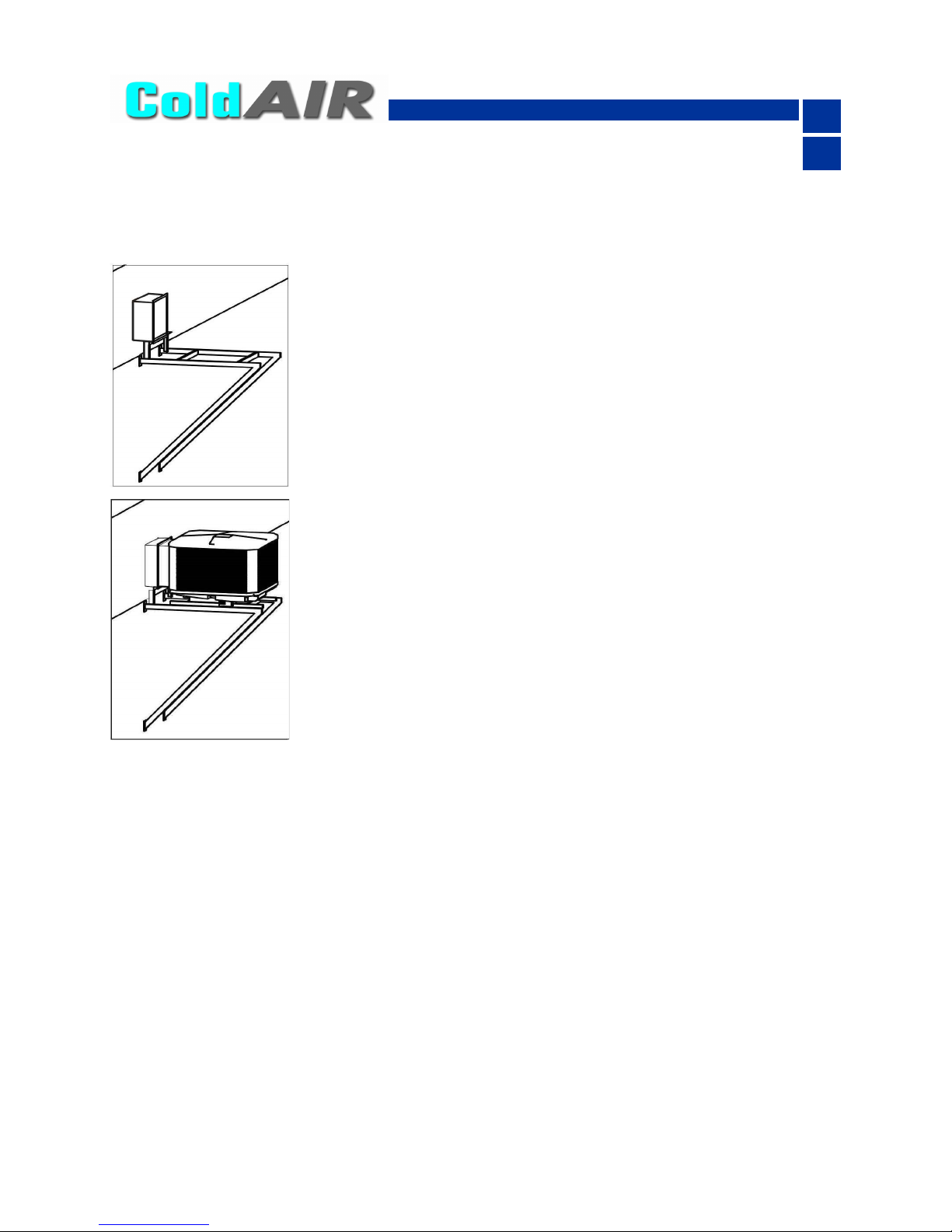
3.2 Installazione a tetto
Predisporre e fissare un canale flangiato di ingresso aria avente le
medesime dimensioni flangia del tronco di canale della macchina
(vedi paragrafo : disegni dimensionali)
La macchina è provvista di un tronco di canale flangiato che andrà
fissato sulla flangia del canale precedentemente predisposto.
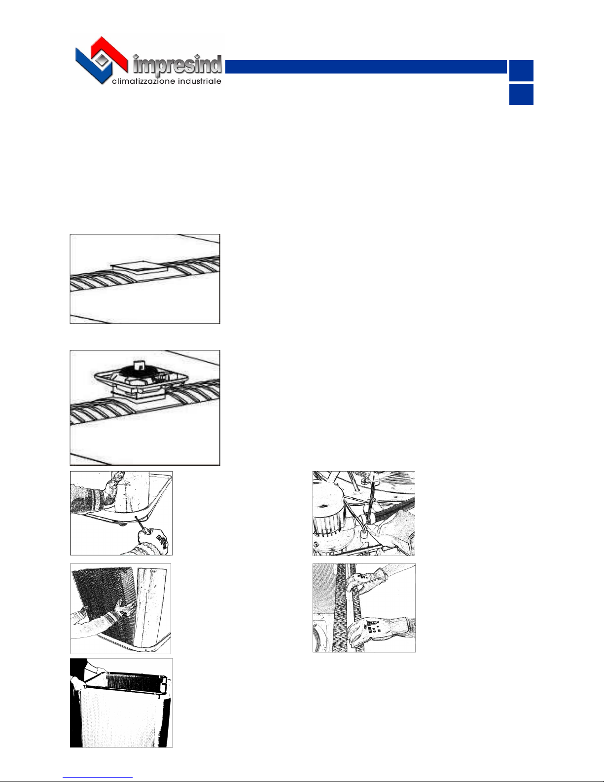
3.2.1 Raffrescatori evaporativi serie TA
Portare la base del raffrescatore evaporativo sul punto di fissaggio.
Procedere al fissaggio delle due flange (base-canale) mediante
bullonatura.
Si consiglia di interporre della pasta siliconica tra i fissaggi delle
flange per garantirne il perfetto isolamento dagli agenti esterni.
Posizionare e fissare i
montanti alla base del
raffrescatore utilizzando
le viti in dotazione
Verificare il serraggio
della fascetta stringi tubo sul tubo flessibile
collegato alla pompa.
Applicare i pannelli umidificanti appoggiandoli
ai montanti mantenendo
la gola, ricavata su un
lato del pannello, verso
l’alto e verso la parte
esterna della macchina.
Inserire il distributore d’acqua nelle gole dei pannelli umidificanti facendo attenzione che i supporti dello stesso appoggino in maniera uniforme sulle piattine di distribuzione.
Mantenere il portagomma in corrispondenza del lato della macchina dove è
presente la pompa dell’acqua, avendo cura di praticare, in corrispondenza del
portagomma stesso, una apertura nel pannello umidificante per permetterne il
passaggio.
Inserire nella gola dei
pannelli le piattine di
distribuzione acqua. Verificare che queste siano ben premute fino a
battuta inferiore della
loro sede.
IT
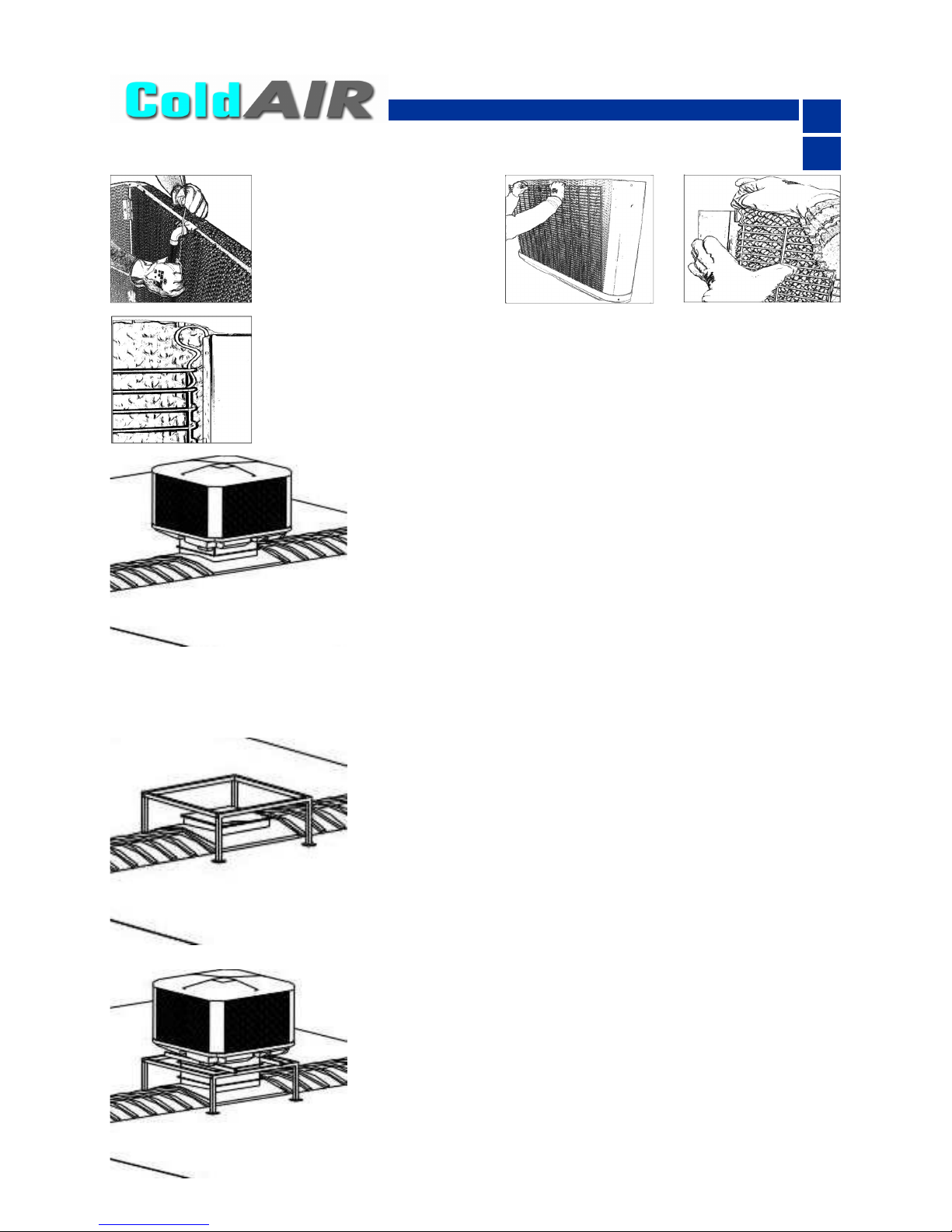
8
Collegare al portagomma
del distributore il tubo
flessibile proveniente dalla pompa e fissarlo mediante fascetta stringitubo.
Inserire le griglie ai lati e al posteriore della macchina, fissandole con i fermagli
forniti in dotazione. Non montare la griglia sul lato anteriore (lato componenti/
collegamenti).
Inserire i fermagli sui due lati della griglia, inizialmente fino al “primo scatto” e
successivamente forzare fino al loro completo inserimento in modo tale che non
sporgano, in altezza, oltre i pannelli umidificanti.
Posizionare il cappello senza fissarlo per permettere il successivo
inserimento della griglia frontale.
Si dovrà sollevare il cappello fino a che la griglia occupi correttamente la propria sede.
Non fissare la griglia frontale con i fermagli perché ciò impedirebbe
un agevole accesso all’interno della macchina per eventuali operazioni di manutenzione.
Dopo avere posizionato la griglia frontale, fissare il cappello mediante le viti in dotazione.
3.2.2 Raffrescatori evaporativi serie TC
Portare il raffrescatore evaporativo sul punto di fissaggio.
Procedere al fissaggio delle due flange (base-canale) e delle barre
al telaio mediante bullonatura.
Si consiglia di interporre tra le due flange (base-canale) un antivibrante a soffietto per evitare la trasmissione di vibrazioni alle canalizzazioni.
Si consiglia di interporre della pasta siliconica tra i fissaggi delle
flange per garantirne il perfetto isolamento dagli agenti esterni.
Predisporre e fissare un telaio per il sostegno della macchina.
La macchina è provvista di un tronco di canale flangiato che andrà
fissato sulla flangia del canale precedentemente predisposto e di
due barre trasversali che andranno appoggiate e fissate al telaio.
Verificare che il telaio di sostegno sia in grado di sopportare il peso
della macchina e tale da non causare vibrazioni e che sia perfettamente in piano (posizionare in bolla). Qualora, per esigenze tecnico
-strutturali è necessario interporre dei supporti antivibranti tra il telaio e le barre bisogna tenerne in conto in fase di studio e realizzazione del telaio stesso e necessariamente provvedere ad utilizzare
giunti elastici sugli attacchi idrici.
IT
9
3.3 Installazione a parete/finestra
3.3.1 Raffrescatori evaporativi serie TA
Predisporre e fissare un telaio per il sostegno della macchina ed un
canale flangiato di ingresso aria avente le medesime dimensioni flangia
del tronco di canale della macchina.
La macchina è provvista di un tronco di canale flangiato che andrà fissato sulla flangia del canale precedentemente predisposto.
Verificare che il telaio di sostegno sia in grado di sopportare il peso della macchina e tale da non causare vibrazioni e che sia perfettamente in
piano (posizionare in bolla).
Portare il raffrescatore evaporativo sul punto di fissaggio.
Procedere al fissaggio delle due flange (base-canale) e della base al
telaio mediante bullonatura.
Si consiglia di interporre della pasta siliconica tra i fissaggi delle flange
per garantirne il perfetto isolamento dagli agenti esterni.
3.3.2 Raffrescatori evaporativi serie TC
Predisporre e fissare un telaio per il sostegno della macchina ed un
canale flangiato di ingresso aria avente le medesime dimensioni flangia
del tronco di canale della macchina.
La macchina è provvista di un tronco di canale flangiato che andrà fissato sulla flangia del canale precedentemente predisposto e di due barre trasversali che andranno appoggiate e fissate al telaio.
Verificare che il telaio di sostegno sia in grado di sopportare il peso della macchina e tale da non causare vibrazioni e che sia perfettamente in
piano (posizionare in bolla). Qualora, per esigenze tecnico-strutturali è
necessario interporre dei supporti antivibranti tra il telaio e le barre bisogna tenerne in conto in fase di studio e realizzazione del telaio stesso e
necessariamente provvedere ad utilizzare giunti elastici sugli attacchi
idrici.
Portare il raffrescatore evaporativo sul punto di fissaggio.
Procedere al fissaggio delle due flange (base-canale) e delle barre al
telaio mediante bullonatura.
Si consiglia di interporre tra le due flange (base-canale) un antivibrante
a soffietto per evitare la trasmissione di vibrazioni alle canalizzazioni.
Si consiglia di interporre della pasta siliconica tra i fissaggi delle flange
per garantirne il perfetto isolamento dagli agenti esterni.
IT
10
3.3.3 Raffrescatori evaporativi serie TA & TC versione “SD”
Predisporre e fissare un telaio per il sostegno della macchina ed un
canale flangiato di ingresso aria avente le medesime dimensioni della bocca di mandata della macchina.
La macchina è provvista di due barre trasversali ( modelli TC) o di un canale di sostegno ( modelli TA)che andranno appoggiate e fissate al telaio
Verificare che il telaio di sostegno sia in grado di sopportare il peso della
macchina e tale da non causare vibrazioni e che sia perfettamente in piano
(posizionare in bolla). Qualora, per esigenze tecnico-strutturali è necessario
interporre dei supporti antivibranti tra il telaio e le barre bisogna tenerne in
conto in fase di studio e realizzazione del telaio stesso e necessariamente
provvedere ad utilizzare giunti elastici sugli attacchi idrici.
Portare il raffrescatore evaporativo sul punto di fissaggio.
Procedere al fissaggio della bocca di mandata alla flangia del canale e delle barre (modelli TC) o tubo di base (modelli TA) al telaio mediante bullonatura.
Si consiglia di interporre tra la bocca di mandata e la flangia del canale un
antivibrante a soffietto per evitare la trasmissione di vibrazioni alle canalizzazioni.
Si consiglia di interporre della pasta siliconica tra i fissaggi delle flange per
garantirne il perfetto isolamento dagli agenti esterni.
Tutte le macchine in versione “SD” hanno un condotto di immissione aria orizzontale (il tronco
posto alla base serve solo come struttura di sostegno e di appoggio)
IT
11
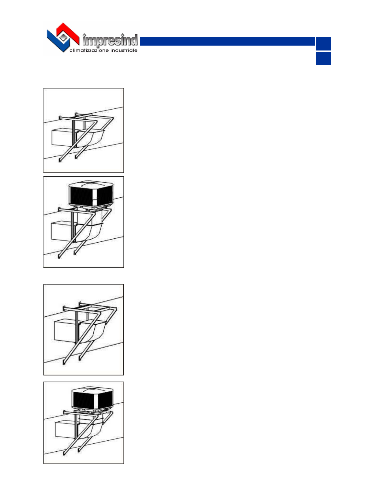
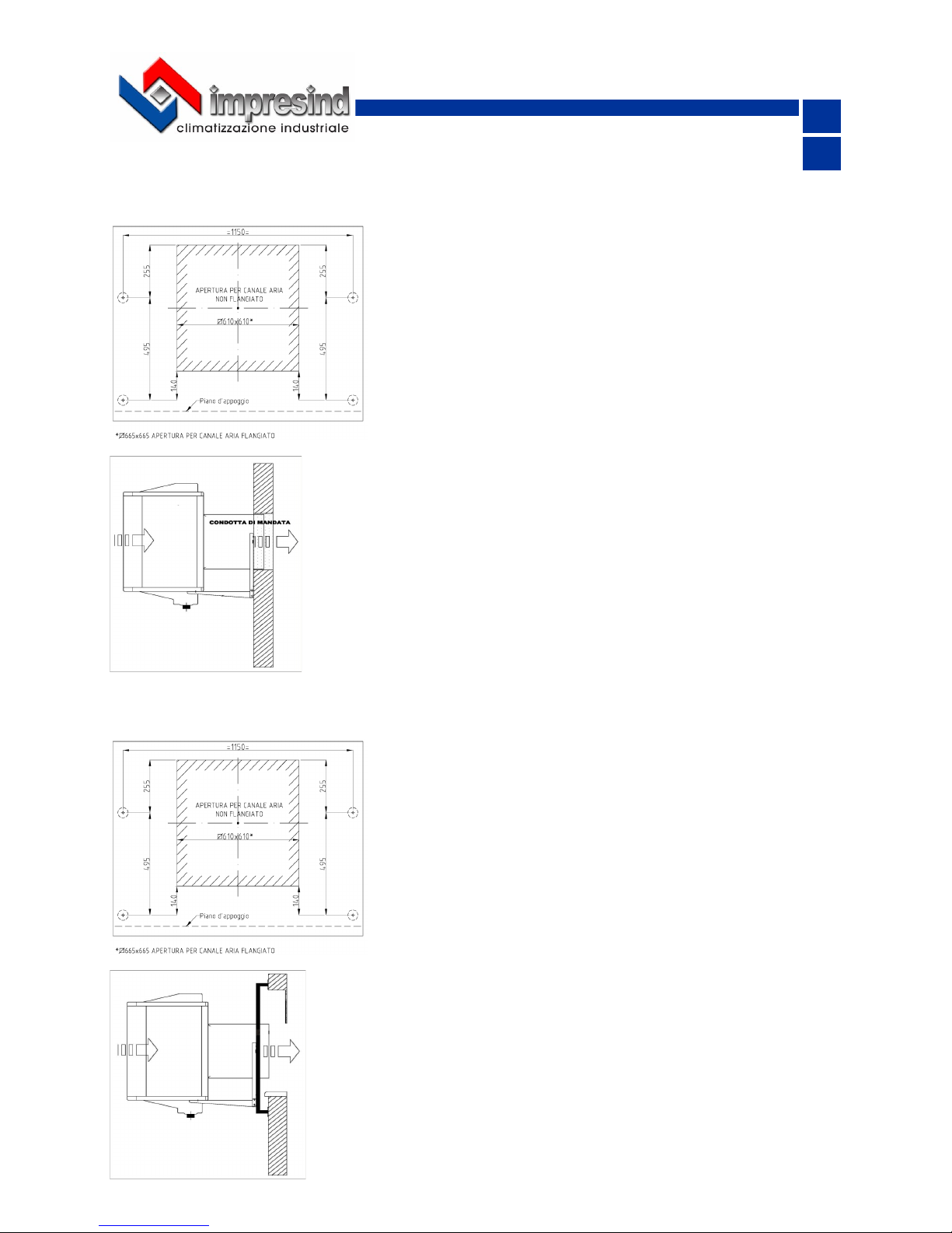
3.3.4 Raffrescatori evaporativi serie FPA
Fissare alla parete la staffa di sostegno, fornita in dotazione alla
macchina, dopo aver predisposto il foro per il passaggio del canale di mandata aria.
3.3.4.1 Installazione a parete
Montare sul lato posteriore del raffrescattore evaporativo (lato
ventilatore) il primo tratto del canale di mandata aria di sezione
quadra 600x600.
Posizionare il raffrescatore evaporativo sulla staffa di sostegno e
spingerlo fino al contatto con i montanti posteriori della staffa
stessa.
Fissare il raffrescatore evaporativo alla staffa mediante apposite
squadrette e le relative viti autoperforanti fornite in dotazione.
Predisporre un foro sul vetro per il passaggio del canale di mandata aria ed un telaio fissato alla parete (sovrastante e sottostante il vetro) avente lo stesso interasse della staffa di sostegno fornita in dotazione per il montaggio della staffa di sostegno stessa.
3.3.4.2 Installazione a finestra
Fissare la staffa di sostegno, fornita in dotazione, sul telaio precedentemente predisposto.
Montare sul lato posteriore del raffrescattore evaporativo (lato
ventilatore) il primo tratto del canale di mandata aria di sezione
quadra 600x600.
Posizionare il raffrescatore evaporativo sulla staffa di sostegno e
spingerlo fino al contatto con i montanti posteriori della staffa
stessa.
Fissare il raffrescatore evaporativo alla staffa mediante apposite
squadrette e le relative viti autoperforanti fornite in dotazione.

3.4 Note a completamento
12
IT
Predisporre all’interno dell’edificio i punti d’ancoraggio per le catene di sostegno della condotta
d’immissione aria. Questi dovranno essere definiti in modo tale che le catene non provochino eccessivi sforzi sulla condotta stessa. Accertarsi che questa sia in asse con la macchina
Per l’ancoraggio al soffitto o a parete dei canali utilizzare catene e relativi accessori muniti di certificato di collaudo, realizzati in acciaio zincato o inox, aventi il diametro del filo non inferiore a 3mm o
comunque dimensionato in relazione al peso che dovrà sostenere, tenendo conto dei margini di
sicurezza imposti dalle normative.
Non utilizzare componenti in leghe d’alluminio o similari
I canali devono essere dimensionati in funzione dell’impianto e delle caratteristiche aerauliche del ventilatore. Un errato calcolo delle canalizzazioni causa perdite o eccessi di potenza
provocando possibili anomalie di funzionamento.
Al termine dell’installazione dell’impianto, ruotare verso l’esterno le alette dei diffusori e regolarle in modo
ottimale per direzionare il flusso d’aria.
3.5 Allacciamento alla rete elettrica
Ogni apparecchio deve essere collegato alle rete di alimentazione elettrica attraverso un sezionatore
onnipolare avente una distanza minima fra i contatti di almeno 3 mm e un interruttore magnetotermico salvamotore predisponendoli in una posizione facilmente raggiungibile dall’utente.
L’impianto elettrico deve essere realizzato in conformità alle norme vigenti del paese in cui la macchina verrà installata.
L’allacciamento alla rete elettrica deve essere obbligatoriamente eseguito da personale abilitato.
Tutta la componentistica utilizzata per l’ allacciamento elettrico deve essere di tipo certificato. Prima di iniziare qualsiasi operazione assicurarsi che la linea di alimentazione generale
sia sezionata.
Prevedere un efficace collegamento di messa a terra.
Il raffrescatore è fornito di un quadro elettrico di collegamento, applicato alla base-canale, contenente
un sezionatore per il collegamento alla linea di alimentazione elettrica e una morsettiera per il collegamento dei cavi del modulo di comando remoto e di un modulo di comando remoto dell’apparecchio
da posizionarsi all’interno dell’ambiente. Per il collegamento alla linea di alimentazione elettrica, utilizzare un cavo multipolare + terra di tipo previsto dalle normative vigenti.
Per il collegamento del display, utilizzare un cavo schermato del tipo 20 AWG - 5 poli con sezione
min. 0,50 mm2 – Sviluppo massimo : 25 metri.
Eseguire i collegamenti seguendo lo schema di riferimento che potrete trovare in fondo a questo manuale o all’interno del quadro di comando (vedasi anche paragrafo: schemi di collegamento elettrico)
E’ assolutamente necessario rispettare la polarità delle fasi e/o la numerazione dei cavi/morsetti.

IT
13
3.6 Allacciamento alla rete idrica
Il raffrescatore Cold Air è dotato, per l’alimentazione dell’acqua, di un attacco da 3/8” presente nella
parte inferiore al quale si consiglia di prevedere un collegamento con un rubinetto di intercettazione
ed un sistema che permetta lo svuotamento dell’impianto prima della stagione invernale.
Inserire un filtro antisabbia sull’impianto di alimentazione idrica della macchina.
E’ necessario realizzare una condotta in grado di garantire una portata minima di 5 ÷10 l/minuto ad
una pressione di 1.5 ÷ 3 bar ( pressione massima consentita : 6 bar ).
Si consiglia di realizzare la condotta dell’acqua all’interno del fabbricato, in caso contrario prevedere
una tubazione adeguatamente isolata.
Si raccomanda l’utilizzo di acqua potabile, di durezza non superiore ai 27°f e non inferiore ai 7°f.
In caso di durezza superiore, dotare l’impianto di un sistema di addolcimento. Non utilizzare acqua
demineralizzata.
Procedere al collegamento del manicotto da 3/8” alla rete idrica principale
senza sollecitarlo eccessivamente
La macchina è inoltre dotata di un manicotto filettato ø60 mm per lo scarico dell’acqua
Collegare al manicotto la tubazione flessibile in dotazione fissandola mediante fascetta stringi tubo ponendo attenzione a non sollecitare il manicotto
stesso ed evitando assolutamente che questo possa ruotare.
Se dovesse essere presente un sistema di scarico centralizzato, convogliare
il tubo al sistema di scarico centralizzato secondo le norme igieniche vigenti
nel paese in cui la macchina verrà installata.
SEZIONE 4 – SISTEMI DI PROTEZIONE
4.1 Dispositivi di protezione
Per ottemperare alle disposizioni contenute nelle Direttive Comunitarie applicabili all’unità alla quale è
riferito il presente manuale d’uso e manutenzione, Impresind Srl ha predisposto sull’unità stessa i sistemi di sicurezza previsti dalla legislazione vigente.
4.2 Segnaletica applicata a bordo macchina
ORGANI ELETTRICI SOTTO TENSIONE
segnala il pericolo dovuto a parti elettriche sotto tensione
ORGANI MECCANICI
segnala il pericolo dovuto a parti meccaniche in movimento
4.3 Abbigliamento
Essendo l’apparecchio destinato ad installazioni in posizioni non direttamente raggiungibili dagli utenti durante il normale utilizzo, non sono applicabili particolari prescrizioni per l’abbigliamento del personale.

14
IT
4.4 Rischi residui
Prestare attenzione al movimento del ventilatore. Non introdurre gli arti. Pericolo meccanico
Vietato utilizzare acqua per pulire componenti elettromeccanici.
Pericolo di elettrocuzione
4.5 Situazioni d’emergenza
E’ assolutamente vietato utilizzare acqua per spegnere incendi.
Utilizzare esclusivamente estintori a polvere o ad anidride carbonica.
In caso di emergenza fermare immediatamente l’apparecchio e aprire il circuito elettrico tramite il sezionatore onnipolare, identificare ed eliminare il problema controllandone le cause
di origine, contattare il servizio di assistenza tecnica.
SEZIONE 5 – NOTE SUL FUNZIONAMENTO
Un raffrescatore evaporativo funziona sulla base di un importante principio: introdurre nel locale grandi quantità di aria fresca e rimuovere l’aria calda viziata attraverso porte, finestre o altre aperture d’evacuazione. ARIA FRESCA IN ENTRATA = ARIA CALDA IN USCITA. Un principio molto semplice.
Se in grado di espellere tutta l’aria introdotta, il sistema funzionerà alla sua massima efficacia. Se l’insieme delle aperture non è in grado di espellere il grande volume d’aria introdotto l’efficacia del sistema verrà compromessa. La condizione ideale, è quella di posizionare i diffusori d’aria lontano dalle
aperture (finestre, portoni, ecc.) del locale. Aprendo una finestra lontano dai diffusori, l’aria attraverserà il locale raffrescandolo. Regolando le dimensioni di apertura di finestre e porte, può essere raggiunta la massima efficacia. Non chiudere mai le aperture; chiudendole verranno preclusi i ricambi
d’aria con il conseguente rischio di ridurre l’effetto raffrescante e di aumentare il tasso di umidità relativa all’interno del locale stesso.
Per ottimizzare il rendimento, bisognerebbe garantire circa 0,5 mq di estrazione per ogni 1000 m3
d’aria trattati (fare riferimento ai dati di progetto).
E’ regola di tutti i raffrescatori evaporativi, che più “secca” è l’aria esterna di ricambio, più grande è la
differenza di temperatura o capacità di raffrescamento che potrà essere raggiunta. Il Vostro raffrescatore d’aria non funzionerà al massimo dell’efficienza nei giorni molto umidi, ma raggiungerà ugualmente un livello di raffrescamento efficace.
In aree con umidità elevata il raffrescatore d’aria dovrà essere sovradimensionato per garantire un
maggiore ricambio d’aria o, in altre parole, con una capacità più elevata per compensare la poca differenza di temperatura. In queste aree, il massimo raffrescamento verrà raggiunto assicurandosi che
ci siano più punti d’evacuazione d’aria di quelli sufficienti e che l’unità venga messa in funzione di
mattino presto per bloccare l’aumento del calore latente all’interno dello spazio raffrescato. Il vostro
fornitore progetterà il vostro sistema in funzione delle condizioni climatiche locali. Nei giorni in cui il
tasso d’umidità relativa esterna sarà prossima e superiore al 70%-75%, raccomandiamo di far funzionare l’unità solo in modalità di ventilazione.
L’efficienza di raffrescamento di un sistema non è relativa solo all’efficienza dell’unità impiegata, ma
anche alla progettazione della canalizzazione e all’installazione. Soffitti isolati diminuiranno la temperatura interna significativamente rispetto a soffitti non isolati. Lo stesso concetto è applicabile per la
canalizzazione dell’aria.
Durante il normale funzionamento del sistema in modalità di raffrescamento, il processo di evaporazione produce un accumulo di sali minerali e residui solidi nell’acqua di scarico; quest’acqua NON E’
POTABILE.

GB
INDEX
GENERAL INFORMATION ............................................................................................................................... 3
Preamble ......................................................................................................................................................... 3
SECTION 1 – CHARACTERISTICS .................................................................................................................. 4
1.1 Presentation of the ColdAir Evaporative Cooler ....................................................................................... 4
1.2 Foreseen use ............................................................................................................................................ 4
1.3 Machine identification data ....................................................................................................................... 5
1.4 Electrical boards ....................................................................................................................................... 5
SECTION 2 – TRANSPORTATION, HANDLING, UNPACKING, STORAGE .................................................. 5
2.1 Delivery of the unit .................................................................................................................................... 5
2.2 Transportation, handling and lifting .......................................................................................................... 5
2.2.1 Lifting with fork lift .................................................................................................................................. 5
2.2.2 Lifting with cables .................................................................................................................................. 6
2.3 Unpacking the equipment ......................................................................................................................... 6
2.4 Storage ..................................................................................................................................................... 6
SECTION 3 – POSITIONING and INSTALLATION .......................................................................................... 7
3.1 General warnings ..................................................................................................................................... 7
3.2 Roof installation ........................................................................................................................................ 7
3.2.1 TA evaporative coolers .......................................................................................................................... 7
3.2.2 TC evaporative coolers .......................................................................................................................... 8
3.3 Wall/window installation ............................................................................................................................ 9
3.3.1 TA evaporative coolers .......................................................................................................................... 9
3.3.2 TC evaporative coolers .......................................................................................................................... 9
3.3.3 TA & TC evaporative coolers “SD” version .......................................................................................... 10
3.3.4 FPA evaporative coolers ..................................................................................................................... 11
3.3.4.1 Wall installation .................................................................................................................................... 11
3.3.4.2 Window installation .............................................................................................................................. 11
3.4 Notes ....................................................................................................................................................... 12
3.5 Connection to the power supply ............................................................................................................. 12
3.4 Connection to the water supply .............................................................................................................. 13
SECTION 4 – PROTECTION DEVICES .......................................................................................................... 13
4.1 Protection devices .................................................................................................................................. 13
4.2 Caution signs .......................................................................................................................................... 13
4.3 Clothing ................................................................................................................................................... 13
4.4 Residual risks ......................................................................................................................................... 14
4.5 Emergency situations ............................................................................................................................. 14
SECTION 5 – FUNCTIONING NOTES ............................................................................................................ 14
TECHNICAL DRAWINGS & FEATURES ....................................................................... 15-16-17-18-19-20-21
2

GENERAL INFORMATION
PREAMBLE
Dear Customer,
We thank you for chosing an Impresind product and we would like to inform you that:
• The contents of this document are for information purposes only and are subject to modifica
tions without notice;
• This manual cannot be partially or fully reproduced, transmitted, copied or stored in an archive
system in any mechanical, magnetic, optical, chemical or other form or means without written
authorization by Impresind S.r.l.
The workers using and maintaining the machine must be fully aware of its contents before the machine is placed in service.
If the manual is misplaced or damaged, immediately request a copy by contacting Technical Assistance Service at Impresind Srl, indicating the identification data of the plant shown on the machine
identification plate and on the cover of this manual.
The machine is conforming to the following European Community Directives:
2006/42/CE Machinery Directive
2014/35/UE Low Voltage Directive
2014/30/UE Electromagnetic Compatibility Directive
2009/125/UE Ecodesign Directive
GB
3

IT
4
SECTION 1 – CHARACTERISTICS
1.1 Presentation of the ColdAir Evaporative Cooler
To improve the summer microclimate inside a production unit, sales or other area, it is necessary to
ventilate the environment with frequent changes of fresh, filtered and possibly cool air. For large areas such as industrial buildings, an air conditioning plant is frequently not adaptable due to the great
volume of air to be cooled and the thermal loads of processes to be neutralized, the necessary
amount of energy is very high and the cooling effect is reduced by the exhaust air extraction plant
and by frequent opening of the doors during normal activity.
Evaporative cooling plants that cool the air using a natural principle represent an optimal solution: the
air passes through special wet water filters, loosing part of its heat during the evaporation process of
the water and hence lowering the air temperature. The absence of refrigeration plants reduces energy consumption to a minimum and enables great volumes of air to be treated for the many air changes necessary.
1.2 Foreseen use
The ColdAir evaporative cooler can be installed in all environments where it is necessary to improve
the microclimate, where the environment must be ventilated with frequent changes of fresh, filtered
and possibly cool air, such as
• production buildings and units
• sales areas and warehouses
• sport areas such as gymnasiums;
It is absolutely forbidden to make modifications to the machine and its destination of use.
Impresind Srl declines all responsibility for any damages which may be, directly or indirectly,
caused to exposed persons or property, due to improper use or use of the machine for different purposes other than the design purposes, incorrect installation, inappropriate power supply, different or changes to the installation environment from the one declared during order
confirmation, grave deficiency of maintenance, unauthorized alterations and modifications,
use of non-original spare parts, removal of the protection guards, inobservance of the instructions for use, negligence, etc.
The machine must NOT be used for a different use than its designed use for any reason whatsoever or used in a different way than stated in this manual.
DO NOT install the machine in closed areas; the machine must be installed outside the area to
be treated, except by specific approval of the manufacturer.
DO NOT lay weights on the machine
Do NOT start-up the machine if it is not connected to the relative plant ( duct ) of air distribution.
When the plant is operating, do not touch the fan – Mechanical danger.
It is forbidden to work on moving parts.
It is absolutely forbidden to install Cold AIR evaporative cooling plants in potentially explosive environments.
GB
4

GB
5
1.3 Machine identification data
Machine identification data is shown on the warranty sheet supplied to the customer and is enclosed
in the documentation and on the machine identification plate.
If Technical Assistance or spare parts are required, always supply the machine model and
serial number.
1.4 Electrical boards
Any electrical boards supplied by Impresind s.r.l. are manufactured according to EN 60204/1:2016
regulations.
It is absolutely forbidden to make modifications to the electrical board.
SECTION 2 – TRANSPORTATION, HANDLING, UNPACKING, STORAGE
2.2 Transportation, handling and lifting
Check the packaging and its contents, if damage due to transportation is found, make a reserve for the damage on the shipping documents to be signed by the shipping agent and
send a copy by fax or mail (impresind@impresind.it) to Impresind Srl.
Take care when handling Evaporative Cooling units during unloading from the transportation
means, handle and position to avoid damages to the equipment.
Avoid contact with elements, which may damage the equipment.
IMPRESIND s.r.l. declines any responsibility for damage caused during transportation, loading and unloading of the evaporative cooling units
2.1 Delivery of the unit
When the unit is delivered, the customer MUST check the state of the goods.
2.2.1 Lifting with fork lift
Widen the forks as much as possible to balance the load. Dip the ends of the forks to avoid damaging
the bottom of the machine.

GB
6
2.2.2 Lifting with cables
We suggest to attach the cables as shown, inserting spacers of an adequate length to prevent the
cables from damaging the casing when tightened.
Because of the heavy weight, TC models and “SD” version, when unpacked, are provided with punched brackets to allow to lift them by using appropriate metal tubes.
Place the goods down with care, avoiding sudden movements or, worse, dropping the goods.
2.3 Unpacking the equipment
IT IS ABSOLUTELY FORBIDDEN to station under suspended loads and inside the movement
area of the lifting equipment
When handling the units, use suitable means according the weights involved, as envisaged
by EC Directive 89/391 and subsequent amendments.
Lifting must only be carried out by qualified personnel.
Free items from the packaging material and collect the packaging to avoid potential danger of fire and
suffocation of persons or animals.
Leave the machine on its packaging base until the installation to avoid damages
Disposal of packaging materials must be conform to the regulations in force in the country of
destination where the evaporative cooling unit is installed.
2.4 Storage
During transportation and storage, make sure that the environmental temperature is between -10
and 50 °C.
If the ColdAir evaporative cooling unit must be stored, make sure that the relative humidity in the
warehouse is between 5% and 90%.

GB
7
SECTION 3 – POSITIONING AND INSTALLATION
3.1 General warnings
Before proceeding to install, make sure that each evaporative cooling unit has been unpacked and
checked for damage (check any components).
Positioning and installation of the evaporative cooling units must be carried out by qualified personnel
and by observing the laws in force in the country of destination.
3.2 Roof installation
Prepare and fix an air inlet flanged duct . The flange has to be of
the same dimension of the unit’s trunk duct flange
(view paragraf: technical drawing).
The unit is equipped with a trunk of flanged duct that will be fixed to
the flange of the inlet duct prepared before.
3.2.1 TA Evaporative coolers
Position the evaporative cooler base to the inlet duct and fix the two
flanges (base duct flange-inlet duct flange) together by using provided bolts.
It is recommended to insert some silicon paste between the two
flanges to guarantee perfect insulation from external agents.
Position and fix the 4
coloumns at the cooling
unit base by using provided screws.
Check the tightness of
the pump flexible hose
clamp.
Positioning and applying cooling pads. Maintain the groove (made
on one side of the pad)
in the upper position
and towards the external part of the machine
Insert the water distributor into the pad grooves and make sure that the water
distributor rests in a uniform manner over the distribution stripes.
Maintain the hose-end fitting on the side of the water pump. Make a hole
through the pads to allow the passage of the hose-end fitting.
Insert the water distribution stripes into the pad
grooves.
Check that stripes are
well pressed down to
the bottom of their seat.

GB
8
Connect the distributor
hose-end fitting to the
flexible hose coming
from the pump and fix
them with an hose
clamp.
Insert the grates on the sides and rear of the unit and fix them by using the clips
provided. Do not assemble the front unit grate (connections/components side).
At first insert the clips till to their first “click” on the two upper corners of the grate.
Finally force the clips until they are completely inserted so that they do not protrude from the cooling pads.
Position the cap without fixing it to allow the front unit grate insertioning.
The cap must be lifted so the grate slots into its seat.
Do not use clips to fix the front unit grate to facilitate any necessary
maintenance operation.
Once the protection grates have been positioned, fix the cup by
using supplied screws.
3.2.2 TC Evaporative coolers
Position the evaporative cooler on the inlet duct.
Fix the two flanges (base duct flange-inlet duct flange) together and
the bars at the frame by using provided bolts.
We suggest to insert an outlet flexible connection between the two
flanges to avoid vibrations transmitted through the ducts.
We suggest to insert silicone sealant between flanges to guarantee
perfect insulation from external agents.
Prepare and fix an air inlet flanged duct and a frame to hold up the
unit. The flange has to be of the same dimension of the unit’s trunk
duct flange.
The unit is equipped with a trunk of flanged duct that will be fixed to
the flange of the inlet duct prepared before and with two side girders bars that will be fixed to the prepared frame.
Verify that the frame is designed to well support the weight of the
machine, doesn’t cause vibrations and it must be perfectly horizontal. If necessary to insert antivibration dumpers between frame and
the bars, this needs to be planned before manufacturing the frame
and consider to insert flexible couplings in the hydric connections.

GB
9
3.3 Wall/window installation
3.3.1 TA evaporative coolers
Prepare and fix an air inlet flanged duct and a frame to hold up the unit.
The flange has to be of the same dimension of the unit’s trunk duct flange.
The unit is equipped with a trunk of flanged duct that will be fixed to the
flange of the inlet duct prepared before and with two side girders bars
that will be fixed on the frame.
Verify that the frame is designed to well support the weight of the machine, doesn’t cause vibrations and it must be perfectly horizontal.
Position the evaporative cooler to the inlet duct.
Fix the two flanges (base duct flange-inlet duct flange) together by using
provided bolts.
We suggest to insert silicone sealant between flanges to guarantee perfect insulation from external agents.
3.3.2 Raffrescatori evaporativi serie TC
Prepare and fix an air inlet flanged duct and a frame to hold up the unit.
The flange has to be of the same dimension of the unit’s trunk duct flange.
The unit is equipped with a trunk of flanged duct that will be fixed to the
flange of the inlet duct prepared before and with two side girders bars
that will be fixed on the frame.
Verify that the frame is designed to well support the weight of the machine, doesn’t cause vibrations and it must be perfectly horizontal. If
necessary to insert antivibration dumpers between frame and bars, this
needs to be planned before manufacturing the frame and consider to
insert flexible couplings in the hydric connections.
Position the evaporative cooler on the inlet duct.
Fix the two flanges (base duct flange-inlet duct flange) together and the
bars at the frame by using provided bolts.
We suggest to insert an outlet flexible connection between the two flanges to avoid vibrations transmitted through the ducts.
We suggest to insert silicone sealant between flanges to guarantee perfect insulation from external agents.

GB
10
3.3.3 TA & TC evaporative coolers “SD” version
Prepare and fix an air inlet flanged duct and a frame to hold up the unit. The
duct has to be of the same dimension of the unit’s air outlet .
The unit is equipped with two side girders bars (fot TC models) or vertical
duct structure (for TA models) that will be fixed on the frame.
Verify that the frame is designed to well support the weight of the machine,
doesn’t cause vibrations and it must be perfectly horizontal. If necessary to
insert antivibration dumpers between frame and bars, this needs to be
planned before manufacturing the frame and consider to insert flexible couplings in the hydric connections.
Position the evaporative cooler to the inlet duct.
Fix the two flanges (base duct flange-inlet duct flange) together and the
bars (for TC models) or structural duct (for TA models) at the frame by
using supplied bolts.
We suggest to insert an outlet flexible connection between the unit air outlet
and the duct to avoid vibrations.
We suggest to insert silicone sealant between flanges to guarantee perfect
insulation from external agents.
The “SD” version machine have a orrizontal ait duct (and not vertical duct). The duct provide at
the base of machine , it is not the air duct; but it is a structural working.

GB
11
3.3.4 FPA evaporative coolers
When the hole in the wall for the passage of the air inlet duct is
done, fix the supplied support bracket to the wall.
3.3.4.1 Wall installation
Install the first section of air duct (area 600x600) on the rear of
the unit (fan side).
Position the unit on the support bracket and push it towards the
wall untill it gets contact with the support bracket coloumns.
Fix the unit at the supplied side bracket by using the supplied
screws.
Prepare a hole through the window for the air inlet duct passage
and a frame fixed to the wall (window bridge) with the same dimension as the supplied support bracket.
3.3.4.2 Window installation
Fix the supplied support bracket at the prepared frame.
Install the first section of air duct (area 600x600) on the rear of
the unit (fan side).
Position the unit on the support bracket and push it towards the
wall untill it gets contact with the support bracket coloumns.
Fix the supplied side brackets to the unit by using supplied
screws.

GB
12
3.4 Notes
Inside the building, prepare the anchor points for the support chains of the air inlet duct. These must
be placed in a position to avoid excessive stress to the air inlet duct and make sure they are on the
same axis as the machine.
To anchor the unit to the ceiling or to the wall, use chains and accessories having the necessary
test certificates, made from zinc-plated steel or stainless steel and having a wire diameter of no less
than 3 mm or dimensioned for the weight to be supported, bear in mind safety margins imposed by
regulations.
Do not use aluminium alloy or similar components.
The ducts must be sized according to the ratings of the system and the characteristics of the
fan. Incorrect calculation of the size of the ducting may lead to a drop or an increase in output, causing the activation of any safety devices in the system
At the end of the installation, adjust the diffuser flaps
to better direct the air flow.
3.5 Connection to the power supply
Each unit must be connected to the power supply using an Omnipolar switch. The isolator must have
a distance between its contacts of at least 3 mm for each pole and must be placed in a position that
can be easily reached by the user. The electrical plant must be constructed according to the regulations in force in the country where the machine is installed.
Connection to the power supply MUST be carried out by qualified personnel.
All components used to connect the power supply must be certified.
Before working on the power supply cables, make sure that power has cutted-off.
Provide an efficient earth connection.
The unit is supplied with an electrical switch box for the connections, this is placed on the external
part of the unit. It contains a main power inlet switch and a domino for the remote control module connection. The unit is supplied also with a remote control module to be installed inside the building.
For connection to the power supply, use a multipolar cable + T (earth) according to directives in force
For connection to the remote control device use shielded cable type 20 AWG - 5 poles with a minimum section of 0,50 sq. mm – Maximum length of 25 meters.
It is absolutely necessary to maintain the polarity of the electrical phases and the numbers on the
wires/terminals.

GB
13
3.6 Connection to the water supply
The Cold Air cooling unit is connected to the water supply by a 3/8” sleeve attachment found on the
lower part of the equipment, it is advisable to provide a water tap at the water inlet to run dry the plant
before winter.
Insert a sand filter in the water supply plant.
The water piping must guarantee a minimum capacity of 5 -10 Lt/minute at a pressure of 1.5 - 3 bars.
( maximum pressure allowed: 6 bars ).
It is advisable to install the water piping inside the building, to protect it from freezing during winter,
otherwise, insulate it adequately.
It is advisable to use potable water, hardness not more than 27°f and not less than 7°f. If hardness is
more than 30°f, insert a water softener system into the water supply plant. Don’t use demineralized
water.
Proceed to connect the 3/8” connection to the main water supply.
DO NOT use excessive force on the sleeve during its connection to the water
supply.
The unit is also equipped with a Ø60 mm sleeve to discharge water
Connect the supplied flexible hose according to the situation found at the
installation site as mentioned further on, fix the hose by using a hose clamp.
If a discharge system is present, connect the tube to the discharge according
to the regulations in force regarding hygiene in the country where the unit is
installed. No discharge system is present, place the hose in the best way
avoiding any bends.
When connecting the discharge hose, DO NOT use excessive force on the
sleeve and make sure that the sleeve does not rotate.
SECTION 4 – PROTECTION DEVICES
4.1 Protection devices
To comply with the instructions of the European Community Directives, applicable to the unit referred
to in this use and maintenance manual, Impresind Srl has designed the safety systems on the unit
foreseen by the regulations in force
4.2 Caution signs applied on the unit
DANGER: Risk of electric shock
MOVING MACHINERY
4.3 Clothing
The equipment is destined for installation in positions which cannot be directly reached by users during normal operations and therefore particular prescriptions regarding clothing are not necessary.

GB
14
4.4 Residual risks
Pay attention to fan movement. Do not introduce arms or limbs. – Mechanical danger
It is forbidden to use water to clean electro-mechanical components
Electrocution danger
4.5 Emergency situations
It is absolutely forbidden to use water to put out fires, use exclusively powder or CO2 extinguishers.
In case of emergency immediately turn the machine off and cut off the electrical circuit
through the omnipolar isolator switch, identify and solve the problem, contact Impresind after-sales service.
SECTION 5 – FUNCTIONING NOTES
The functioning of the evaporative cooler is based on an important principle: It introduces big quantities of fresh air into the building and removes hot exhausted air through doors, windows and other
openings. If the system is not able to expel the air volume introduced into the building, the efficiency
would be compromised. INLET FRESH AIR = OUTLET HOT AIR a very simple principle.
If the system is able to expel all the air introduced into the building, the system operates at the highest efficiency. The ideal condition is when, into the building, the air diffusers are positioned away
( better on the opposite side) from the openings (windows, doors, etc.) so the air passes through the
building while is cooling it. Maximum efficiency can be reached by adjusting the dimensions of the
window and door openings. Never close the openings: if they are closed, no changes of air will occur,
consequently reducing the cooling effect and increasing the relative humidity level inside the building.
To optimize the system efficiency, consider the following openings for air expulsion:
Guarantee about 0,5 sq.mt of extraction for every 1000 cu.mt. of introduced air (refer to the project
data).
More dry is the external air, more cooling capacity could be reached by the system. Your evaporative
cooling system will not operate at maximum efficiency during high humidity days however it will still
reach an efficient cooling level.
In areas with high relative humidity, the evaporative air cooling system must be oversized to guarantee more air changes, or in other words, it must have higher capacity to compensate the smaller temperature difference given. In these areas, the maximum cooling effect will be reached by making sure
that there are more air evacuation points than normally used and that the units will be switched on
early in the morning to avoid latent heat growing up inside the space to be cooled. Your supplier will
design your system considering your climatic conditions. During days when the relative humidity level
is near to or more than 70%-75%, it is advisable to switch on the system in ventilation mode only.
The cooling efficiency of a system depends on: the cooling unit efficiency, air ducts design, installation quality, building conditions. Insulated ceilings significantly reduce the internal temperature in
comparison with uninsulated ceilings. The same latter concept is applicable to the air duct.
During normal operating conditions in COOLING mode, the evaporation process leaves mineral salts
accumulation and solid residue in the discharge water, this water is NOT POTABLE.

15
FPA109 & FPA159
TA159

16
TA209
TA309

17
TC109
TC209

18
TC109-SD
TA209-2SD

19
SCHEMA ELETTRICO—ELETTRICAL SKETCH

20
CARATTERISTICHE TECNICHE
TECHNICAL FEATURES
Modello
Model
FPA109 FPA159 TA159 TA209 TA209-2SD TA309
Portata d’aria
Air flow
Velocità Max
Fan speed Med
Min
m3/h
10000
7500
5000
13000
9700
6500
13000
9700
6500
20000
15000
10000
20000
15000
10000
27000
19000
13500
Alimentazione
Power supply
Volt 230V/~50Hz 230V/~50Hz 230V/~50Hz 230V/~50Hz 230V/~50Hz 230V/~50Hz
Corrente assorbita
Current
Amp 3,7 4,8 4,8 7 7 9,3
Potenza elettrica
Power consumption
kW 0,9 1,2 1,2 1,8 1,8 2,2
Consumo acqua*
Water consumption*
lt/h 34 39
43 64 66 75
Ingresso acqua
Water inlet
Ø “ 3/8 3/8 3/8 3/8 3/8 3/8
Scarico acqua
Drain
Ø
mm
60 60 60 60 60 60
Canale di mandata
Air outlet duct
mm 600x600 600x600 600x600 1185x590 1185x590 1185x590
Sviluppo max canali
Max lenght of ducts
m 5x1mt.+1curva
5x1mt.+1curve
5x1mt.+1curva
5x1mt.+1curve
5x1mt.+1curva
5x1mt.+1curve
5x1mt.+1curva
5x1mt.+1curve
5x1mt.+1curva
5x1mt.+1curve
5x1mt.+1curva
5x1mt.+1curve
Pann. umidificante
Evaporative pannell
Spessore
Thickness
Superficie
Area
Saturazione
Saturation
efficiency
mm
m2
%
100
2
88
100
2
88
100
2,7
88
100
3,4
88
100
3,1
88
100
4,4
88
Dimensioni LxPxH
Dimensions WxDxH
mm 1300x670x1300 1300x670x1300 1150x1150x1050 1610x1150x1050 1610x1150x1350 1610x1150x1350
Peso (vuoto - pieno)
Weight (empty-full)
kg 60-75 63-78 67-88 120-146 150-180 135-163
Ventilatore tipo
Fan type
Assiale
Axial
Assiale
Axial
Assiale
Axial
Assiale
Axial
Assiale
Axial
Assiale
Axial
* Condizioni di prova:
* Test conditions:
Temp.esterna 33°C
Ext.temp
Umidità rel.est. 60%

21
Modello
Model
TC109 TC109SD TC209
Portata d’aria
Air flow
Velocità Max
Fan speed Med
Min
m3/h
10000
6500
10000
6500
20000
10000
Alimentazione
Power supply
Volt 400V/3N~50Hz 400V/3N~50Hz 400V/3N~50Hz
Corrente assorbita
Current
Amp 3,5 3,5 7
Potenza elettrica
Power consumption
kW 1,6 1,6 3,2
Consumo acqua*
Water consumption*
lt/h 43 43 64
Ingresso acqua
Water inlet
Ø “ 3/8 3/8 3/8
Scarico acqua
Drain
Ø
mm
60 60 60
Canale di mandata
Air outlet duct
mm 600x600 600x600 850x470
Pressione statica
Static pressure
Pa 80 80 80
Pannello umidificante
Evaporative pad
Spessore
Thickness
Superficie
Area
Saturazione
Saturation efficiency
mm
m2
%
100
2,7
88
100
2
88
100
3,4
88
Dimensioni LxPxH
Dimensions WxDxH
mm 1150x1150x1050 1150x1150x1050 1610x1150x1050
Peso (vuoto - pieno)
Weight (empty-full)
kg 110-130 110-130 200-220
Ventilatore tipo
Fan type
Centrifugo
Centrifugal
Centrifugo
Centrifugal
Centrifugo
Centrifugal
* Condizioni di prova:
* Test conditions:
Temp.esterna 33°C
Ext.temp
Umidità rel.est. 60%
CARATTERISTICHE TECNICHE
TECHNICAL FEATURES

Impresind Srl Via 1° Maggio 24, 20064 Gorgonzola (Milano, Italy)
Tel. +39 02 95741932 Fax +39 02 95740637 e-mail impresind@impresind.it
Web www.impresind.it
STP101.119
 Loading...