

Impresind Ray.Red, Ray2E/S, Ray 1E, Ray3/9E, Ray 4E Installation And Operating Instruction
...
Ray.Red
GAS POWER
STP 035GB – 04-18
1
Ray.Red
Istallation and operating instruction
GAS FIRED RADIANT TUBES
GAS POWER
STP035GB-04-18 (valid from 04-2018) TRASLATION OF THE ORIGINAL INSTRUCTION

Ray.Red
GAS POWER
STP 035GB – 04-18
2
INDEX
Part 0: GENERAL INFORMATIONS
0 Introduction ………………………………………………………………………. 4
Part 1: INSTRUCTIONS FOR THE INSTALLER
1 General ………………………………………………………………………. 5
2 Areas of use ………………………………………………………………….. 5
3 Technical data ……………………………………………………………….. 6
4 Radiant unit construction and assembly …………………………………… 7
5 Planning requirements ………………………………………………………. 11
6 Standards, Rules and Regulations ………………………………………… 12
7 Installation ……………………………………………………………………. 13
8 Start up and settings …………………………………………………………. 19
9 Conversion …………………………………………………………………... 21
10 Service ………………………………………………………………………. 21
Part 2: OPERATING INSTRUCTIONS
11 Description of Functioning and Use ………………………………………… 24
12 Suggestions for Energy-Saving Operations …………………………………. 24

Ray.Red
GAS POWER
STP 035GB – 04-18
3
13 Maintenance of the Unit …………………………………………………….. 26
14 If the Unit does not operate properly ………………………………………… 28
Part 3: CAUTIONS AND RESTRICTION
15 Improper Use ………………………………………… 29
16 Dismantling …………………………………. 30
Ray.Red
GAS POWER
STP 035GB – 04-18
4
Part 0: GENERAL INFORMATIONS
0. Introduction
Dear Client,
We thank you to have chosen an Impresind Srl product and inform you that:
• The aim of this guide is only informative and can be subject to variations without
warning;
• This guide cannot be nor partially nor entirely reproduced, diffused, copied or saved in
a storage system in any form or in any media, mechanic, magnetic, optic, chemical or
others, without written authorisation by Impresind Srl.
• This guide has to be conserved until the final dismantling of the product, in case of
property change the guide has to be delivered to the new owner.
• In case of damage and consequent block of the product, Impresind Srl doesn’t refund
eventual economical losses due to the forced block of the product and doesn’t extend
the warranty.
This use and maintenance guide has to be considered as part of the product; it has to be
kept for the entire life cycle of the product.
Impresind Srl declines any responsibility for damages that could, directly or
indirectly, derive by people or objects, due to improper use of the product
or different use from its application field, incorrect installation, not
appropriate supply used, modified or different installation environment
than the one communicated in the order stage, bad maintenance
deficiencies, not authorised interventions and modifications, use of non
original spare parts, removal of active and passive protections, non
observance of the user instructions carelessness, etc.

Ray.Red
GAS POWER
STP 035GB – 04-18
5
Part 1: INSTRUCTIONS FOR THE INSTALLER
1. General
The infrared radiant heaters of this series are gas appliances which can operate on
natural or LPG
They conform with the European Norms ( EN 416-1:2009 ) and
The installation of the gas radiant heaters must conform with the current
national/international regulations for gas appliances and take into account the local
Building Regulations and the requirements of the local gas supply company.
Electrical installation, gas and electrical connection of the appliance must be
undertaken by qualified installers and executed in conformity with regulations in
force in the destination country of the goods.
Because there may be local differences in some of the requirements, the following
recommended installation instructions are not binding. Any necessary approval must
therefore be obtained before the installation is carried out.
2. Areas of use
The gas radiant heaters are fully automatic, direct fired appliances for ceiling or wall
mounting.
They are intended for the heating of halls and large rooms by infrared radiation: they
heat, in the same way as the sun's radiation, the body, the floor, the walls and all the
objects which their radiation reaches and which, for their part, absorb a part of the
energy radiated.
The surrounding space and the air are thus only heated minimally by convection by
the warm surfaces and objects.
Thermal inertia is thus practically eliminated.
The radiant heaters are particularly suited for installation in the following spaces:
- with installation heights between 4 and 9 m dependent on heat output (Guidance:
5.5-7 m generally recommended, dependent on model, 4m for very localised
heating, 9m for background heating)
- in which it is not wished to create any air movement
- in which various temperature ranges or heating time cycles are wanted.
Against this, installation is to be avoided in the following cases:
- installation heights under 3 and above 9-10 m
- where inflammable or explosive materials are being used or can arise
- where air flow rates above 2.5 m/s or high air or ground humidity exist
In some individual cases, the installation can still be possible if special approval is
obtained at the appropriate stage in planning.
Ray.Red
GAS POWER
STP 035GB – 04-18
6
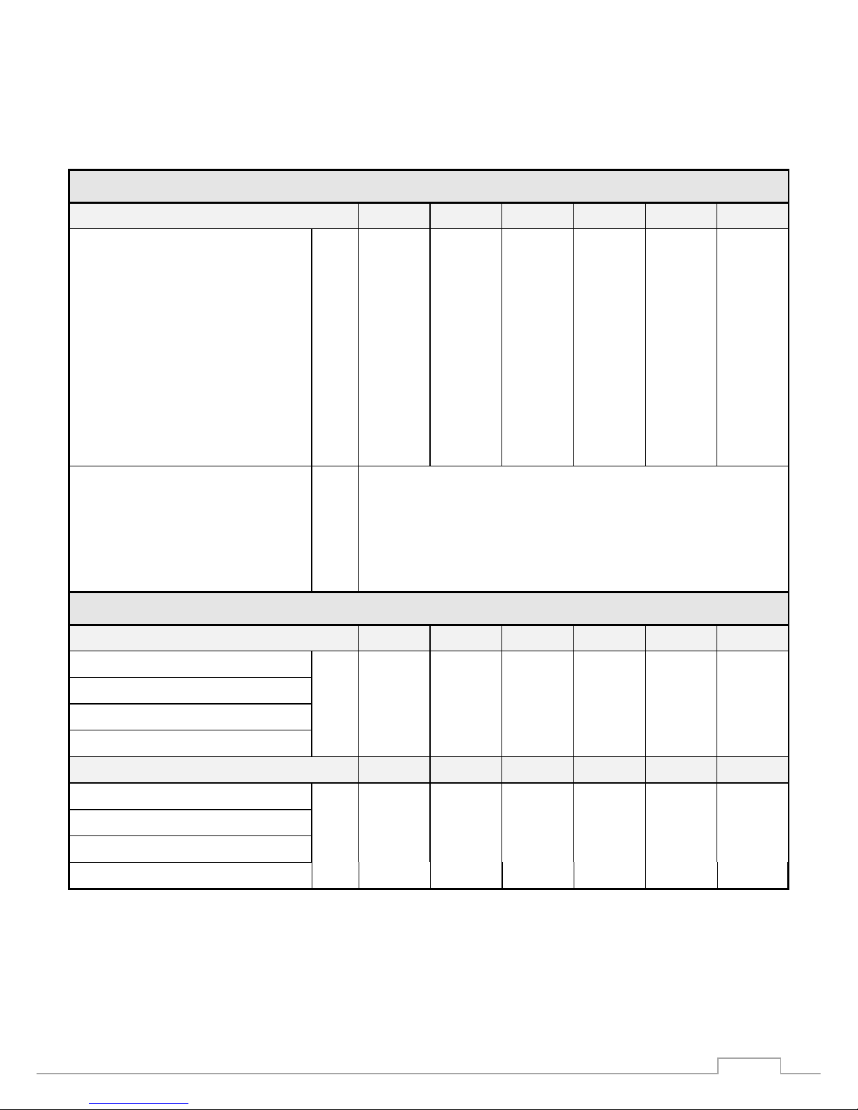
3. Technical data (04-2018)
T E C H N I C A L D A T A
M O D E L Ray 1E Ray2E/S Ray 2E Ray 3E Ray3/9E Ray 4E
Thermal input kW 12,00 19,50 21,00 32,00 32,00 40,00
Gas consumption - Nat. gas – G20 m3/hst 1,25 2,03 2,19 3,33 3,33 4,16
Gas consumption – LPG - G31 kg/hst 0,93 1,50 1,63 2,48 2,48 -
Ø Jet - Nat. gas - G20 mm 2,90 3,80 4,10 5,00 5,00 5,60
Ø Jet - LPG - G31 mm 1,75 2,20 2,40 2,80 2,80 -
Gas supply pressure – G20 (min÷max) mbar 17÷23 17÷23 17÷23 17÷23 17÷23 17÷23
Gas pressure to jet - G20 mbar 9,0 9,0 9,0 9,0 9,0 9,0
Gas supply pressure – G31 (min÷max) mbar 30÷37 30÷37 30÷37 30÷37 30÷37 -
Gas pressure to jet – G31 mbar 30 30 30 30 30 -
Ø Gas connection “ G. ½ “ male
Ø Flue gas connection mm 100 female
Ø Air intake connection mm 100 female
Electrical consumption A 0.50
Electrical supply V 230 ~ 50 Hz. 1 phase
D I M E N S I O N S
“U” Version Ray 1E Ray 2E/S Ray 2E Ray 3E Ray 3/9E Ray 4E
Length mm 3600 5100 6650 6650 8650 10650
Width mm 500 500 670 670 670 670
Height mm 285 285 285 285 285 285
Weight Kg 50 75 120 120 150 200
“L” Version Ray 1E-L Ray 2E/S-L Ray 2E-L Ray 3E-L
Length mm 6550 9550 9550 12550
Width mm 410 410 410 410
Height mm 285 285 285 285
Weight Kg 45 70 105 115
Ray.Red
GAS POWER
STP 035GB – 04-18
7
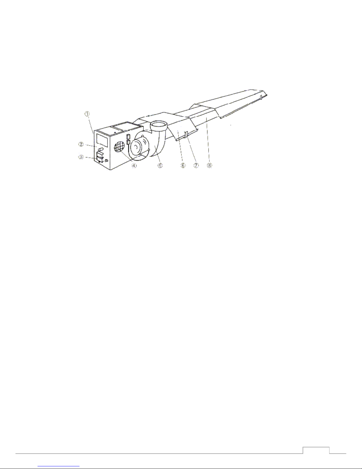
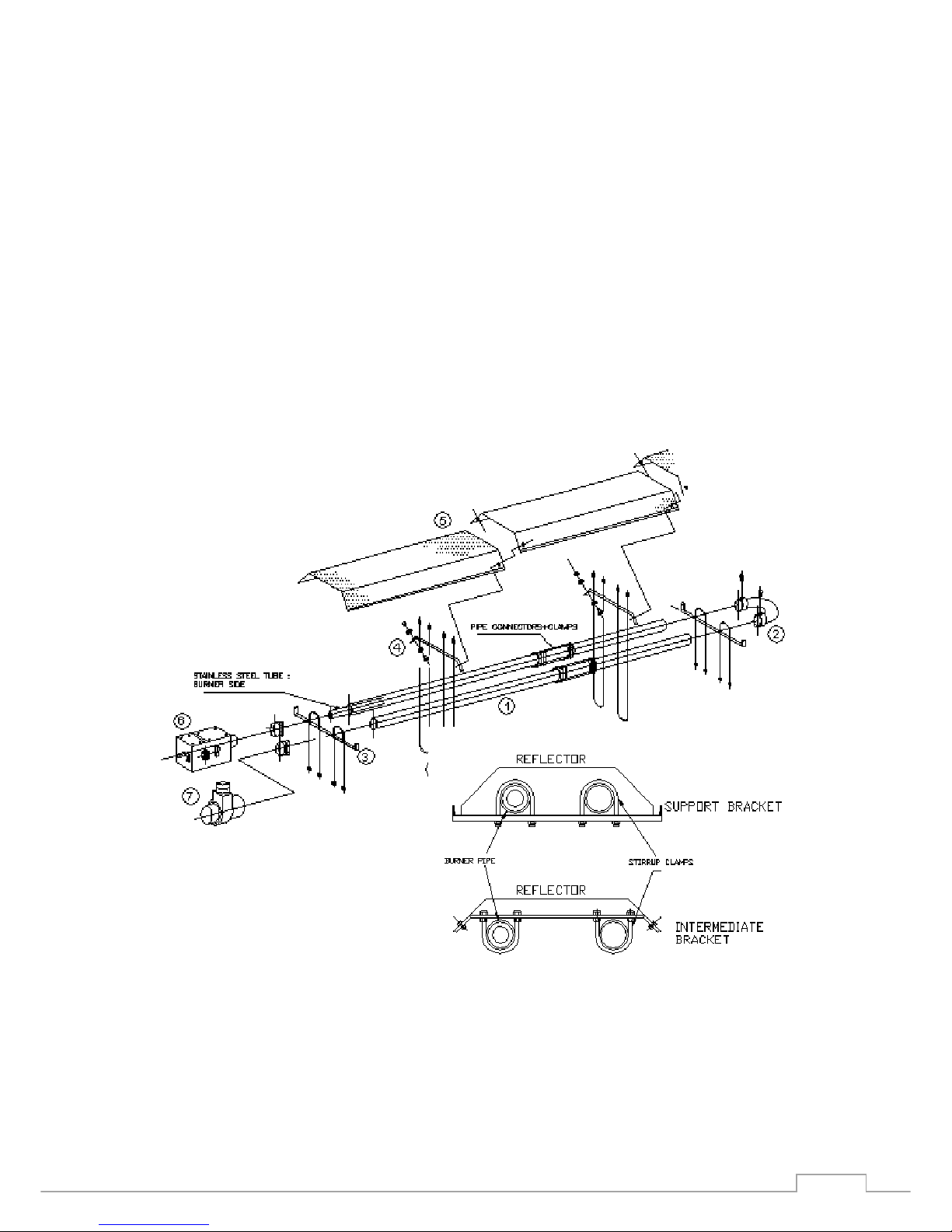
4. Radiant Unit Construction and Assembly.
The gas radiant heaters are constructed from the following main parts:
gas burner, radiant tube, reflector and flue gas fan.
1. Gas Burner 5. Flue gas fan
2. Gas connection 1/2"BSP 6. Reflector
3. Electrical connection 7. Radiant tube support and
(mains and controls plug) mounting bracket
4. Combustion air intake 8. Radiant tube
As delivered, there are the radiant tubes, reflector sections and a carton containing
the following parts: gas burner, flue gas fan, U-bend,pipe connectors (3/9E, 4E and
L versions), support and intermediate brackets, stirrup clamps and reflector screws.
The radiator is assembled as follows - see the drawing which follows and assembly
diagrams.
4.1. Lay the radiant tubes, with both ends free on the appropriate supports,
preferably under the position where it is to be mounted. Note that one end, the
burner end, has an inner stainless steel tube
4.2. Push the U-bend, with the securing screws upwards, onto the tubes until these
are firmly against the shoulders. Tighten the securing screws firmly!
4.3. Place the support brackets on the tubes at both ends and in the middle, place
the stirrup clamps in place and firmly - maintain the distances indicated .
4.4. Lay the intermediate brackets, fasten with the stirrup clamps: first screw the
lower nuts on as far as the end of the thread, insert the stirrup clamps, tighten the
upper nuts.
Important ! After the stirrup clamps are laid in place, the intermediate brackets must
be able to be moved freely on the pipes!

Ray.Red
GAS POWER
STP 035GB – 04-18
8
Remove the protective plastic film from the reflector sections and push them into the
support brackets. Fasten the reflectors to the intermediate brackets with the
provided screws.
If preferred, the reflectors may be fitted after the unit is in place.
4.5. Insert the burner, with the warning lamps downwards, on the pipe until it comes
up against the shoulder. Be sure that the burner is mounted on the pipe with inner
stainless steel tube (look for the inner pipe!). Fasten the clamps.
.

Ray.Red
GAS POWER
STP 035GB – 04-18
9
Ray.Red
GAS POWER
STP 035GB – 04-18
10
Important:
Check the alignment of the burner: The burner axis and the pipe axis must
coincide, misalignment of the burner shortens the life of the pipe! If the mounting is
to be at an angle, the burner must be fitted to the lower pipe and vertically
orientated. Check also that there is a minimum separation between the burner box
and the reflector of 5-10cm.
4.6. Insert the flue gas fan into the free end of pipe until it comes up against the
shoulder, arrange the connection socket horizontally or vertically according to the
flue arrangement, fasten the clamp, plug the motor connection into the socket on the
burner housing.
1.Radiant pipe
2. U-bend
3. Support bracket
4. Intermediate bracket
5. Reflector
6. Gas burner
7. Flue gas fan
8. Stirrup clamps
.
 Loading...