

Impresind Ray.Red, Ray2E/S, Ray 1E, Ray3/9E, Ray 4E Installation And Operating Instruction
...
Ray.Red
GAS POWER
STP 035GB – 04-18
1
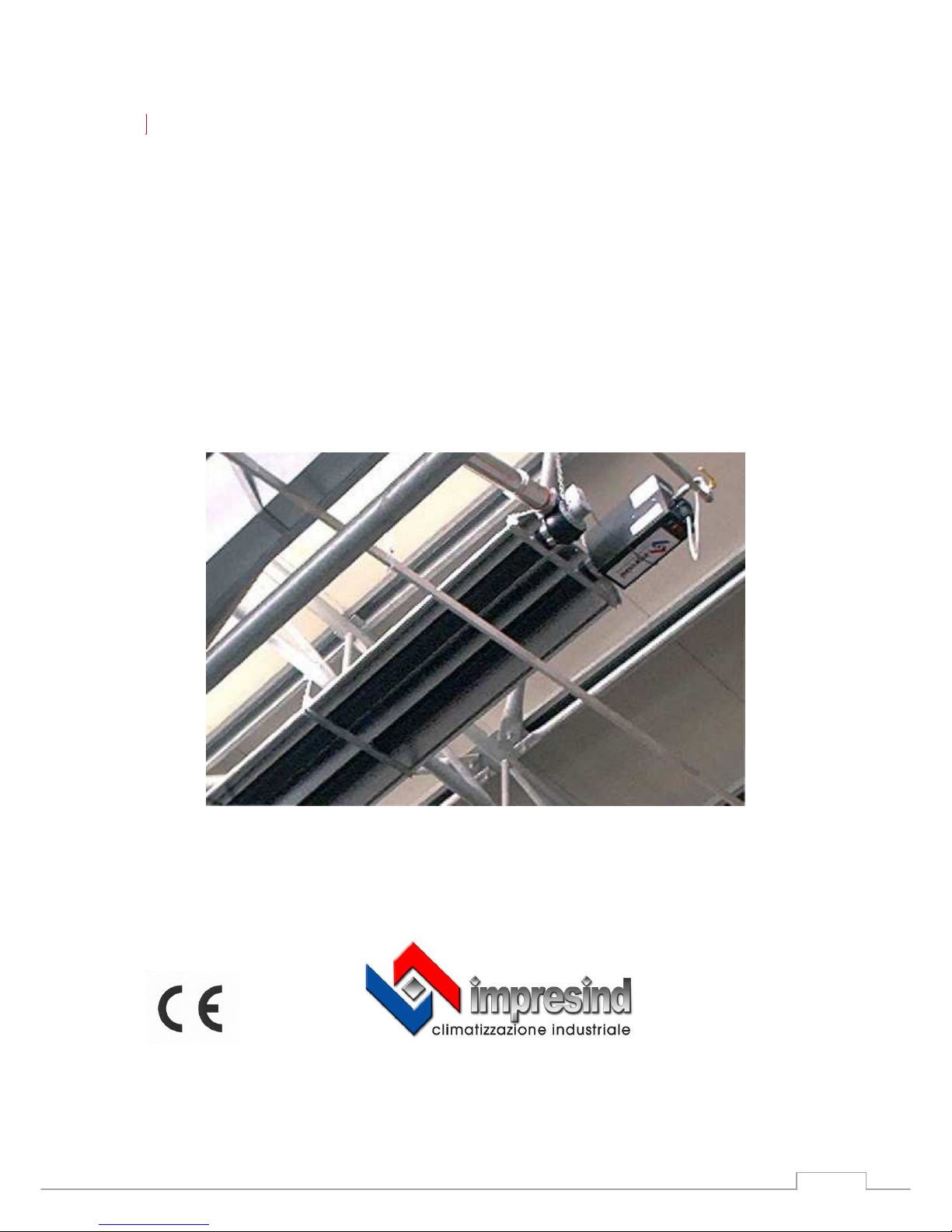
Ray.Red
Istallation and operating instruction
GAS FIRED RADIANT TUBES
GAS POWER
STP035GB-04-18 (valid from 04-2018) TRASLATION OF THE ORIGINAL INSTRUCTION

Ray.Red
GAS POWER
STP 035GB – 04-18
2
INDEX
Part 0: GENERAL INFORMATIONS
0 Introduction ………………………………………………………………………. 4
Part 1: INSTRUCTIONS FOR THE INSTALLER
1 General ………………………………………………………………………. 5
2 Areas of use ………………………………………………………………….. 5
3 Technical data ……………………………………………………………….. 6
4 Radiant unit construction and assembly …………………………………… 7
5 Planning requirements ………………………………………………………. 11
6 Standards, Rules and Regulations ………………………………………… 12
7 Installation ……………………………………………………………………. 13
8 Start up and settings …………………………………………………………. 19
9 Conversion …………………………………………………………………... 21
10 Service ………………………………………………………………………. 21
Part 2: OPERATING INSTRUCTIONS
11 Description of Functioning and Use ………………………………………… 24
12 Suggestions for Energy-Saving Operations …………………………………. 24

Ray.Red
GAS POWER
STP 035GB – 04-18
3
13 Maintenance of the Unit …………………………………………………….. 26
14 If the Unit does not operate properly ………………………………………… 28
Part 3: CAUTIONS AND RESTRICTION
15 Improper Use ………………………………………… 29
16 Dismantling …………………………………. 30
Ray.Red
GAS POWER
STP 035GB – 04-18
4
Part 0: GENERAL INFORMATIONS
0. Introduction
Dear Client,
We thank you to have chosen an Impresind Srl product and inform you that:
• The aim of this guide is only informative and can be subject to variations without
warning;
• This guide cannot be nor partially nor entirely reproduced, diffused, copied or saved in
a storage system in any form or in any media, mechanic, magnetic, optic, chemical or
others, without written authorisation by Impresind Srl.
• This guide has to be conserved until the final dismantling of the product, in case of
property change the guide has to be delivered to the new owner.
• In case of damage and consequent block of the product, Impresind Srl doesn’t refund
eventual economical losses due to the forced block of the product and doesn’t extend
the warranty.
This use and maintenance guide has to be considered as part of the product; it has to be
kept for the entire life cycle of the product.
Impresind Srl declines any responsibility for damages that could, directly or
indirectly, derive by people or objects, due to improper use of the product
or different use from its application field, incorrect installation, not
appropriate supply used, modified or different installation environment
than the one communicated in the order stage, bad maintenance
deficiencies, not authorised interventions and modifications, use of non
original spare parts, removal of active and passive protections, non
observance of the user instructions carelessness, etc.

Ray.Red
GAS POWER
STP 035GB – 04-18
5
Part 1: INSTRUCTIONS FOR THE INSTALLER
1. General
The infrared radiant heaters of this series are gas appliances which can operate on
natural or LPG
They conform with the European Norms ( EN 416-1:2009 ) and
The installation of the gas radiant heaters must conform with the current
national/international regulations for gas appliances and take into account the local
Building Regulations and the requirements of the local gas supply company.
Electrical installation, gas and electrical connection of the appliance must be
undertaken by qualified installers and executed in conformity with regulations in
force in the destination country of the goods.
Because there may be local differences in some of the requirements, the following
recommended installation instructions are not binding. Any necessary approval must
therefore be obtained before the installation is carried out.
2. Areas of use
The gas radiant heaters are fully automatic, direct fired appliances for ceiling or wall
mounting.
They are intended for the heating of halls and large rooms by infrared radiation: they
heat, in the same way as the sun's radiation, the body, the floor, the walls and all the
objects which their radiation reaches and which, for their part, absorb a part of the
energy radiated.
The surrounding space and the air are thus only heated minimally by convection by
the warm surfaces and objects.
Thermal inertia is thus practically eliminated.
The radiant heaters are particularly suited for installation in the following spaces:
- with installation heights between 4 and 9 m dependent on heat output (Guidance:
5.5-7 m generally recommended, dependent on model, 4m for very localised
heating, 9m for background heating)
- in which it is not wished to create any air movement
- in which various temperature ranges or heating time cycles are wanted.
Against this, installation is to be avoided in the following cases:
- installation heights under 3 and above 9-10 m
- where inflammable or explosive materials are being used or can arise
- where air flow rates above 2.5 m/s or high air or ground humidity exist
In some individual cases, the installation can still be possible if special approval is
obtained at the appropriate stage in planning.
Ray.Red
GAS POWER
STP 035GB – 04-18
6
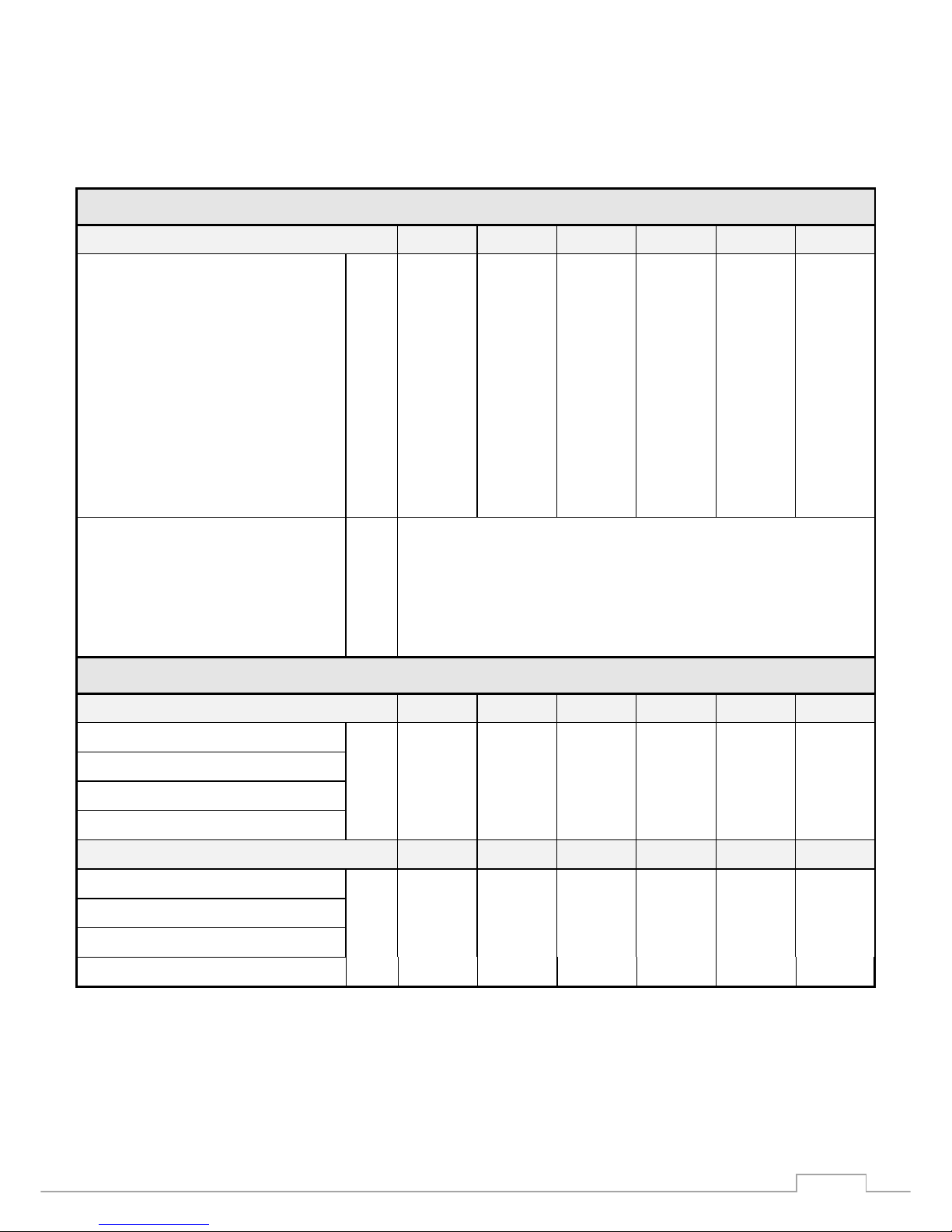
3. Technical data (04-2018)
T E C H N I C A L D A T A
M O D E L Ray 1E Ray2E/S Ray 2E Ray 3E Ray3/9E Ray 4E
Thermal input kW 12,00 19,50 21,00 32,00 32,00 40,00
Gas consumption - Nat. gas – G20 m3/hst 1,25 2,03 2,19 3,33 3,33 4,16
Gas consumption – LPG - G31 kg/hst 0,93 1,50 1,63 2,48 2,48 -
Ø Jet - Nat. gas - G20 mm 2,90 3,80 4,10 5,00 5,00 5,60
Ø Jet - LPG - G31 mm 1,75 2,20 2,40 2,80 2,80 -
Gas supply pressure – G20 (min÷max) mbar 17÷23 17÷23 17÷23 17÷23 17÷23 17÷23
Gas pressure to jet - G20 mbar 9,0 9,0 9,0 9,0 9,0 9,0
Gas supply pressure – G31 (min÷max) mbar 30÷37 30÷37 30÷37 30÷37 30÷37 -
Gas pressure to jet – G31 mbar 30 30 30 30 30 -
Ø Gas connection “ G. ½ “ male
Ø Flue gas connection mm 100 female
Ø Air intake connection mm 100 female
Electrical consumption A 0.50
Electrical supply V 230 ~ 50 Hz. 1 phase
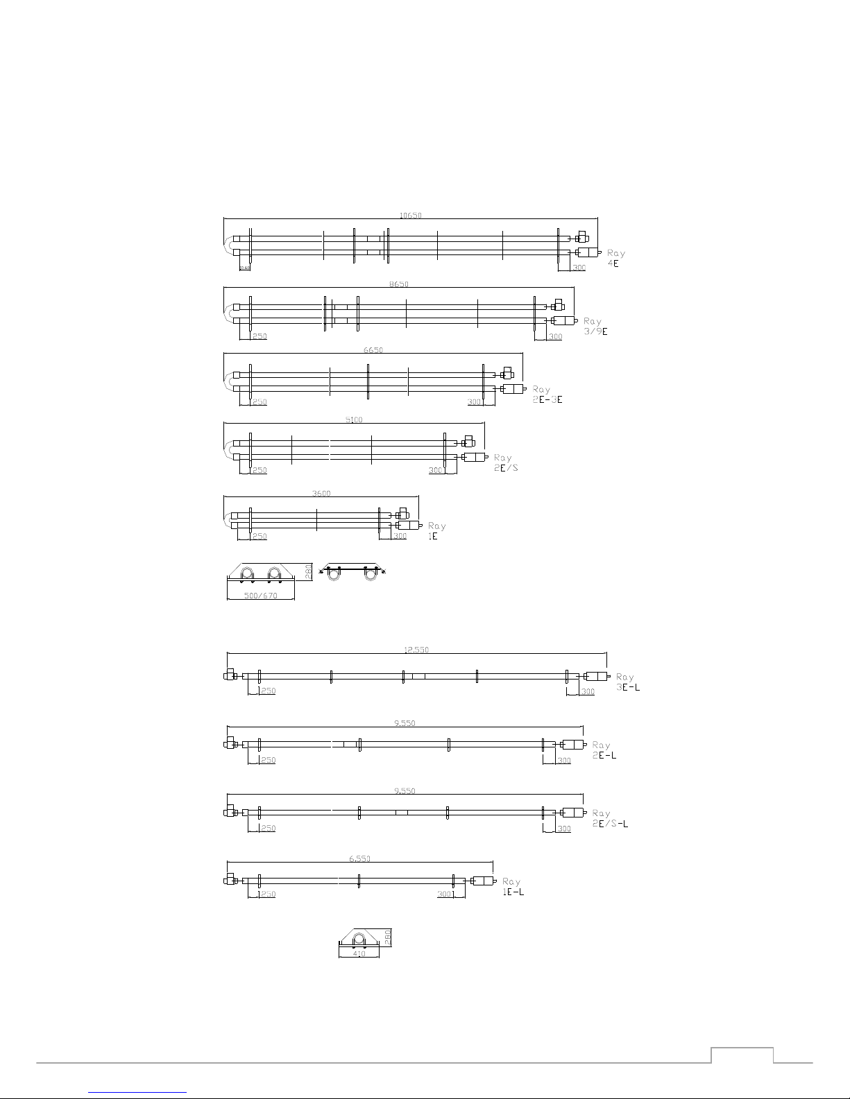
D I M E N S I O N S
“U” Version Ray 1E Ray 2E/S Ray 2E Ray 3E Ray 3/9E Ray 4E
Length mm 3600 5100 6650 6650 8650 10650
Width mm 500 500 670 670 670 670
Height mm 285 285 285 285 285 285
Weight Kg 50 75 120 120 150 200
“L” Version Ray 1E-L Ray 2E/S-L Ray 2E-L Ray 3E-L
Length mm 6550 9550 9550 12550
Width mm 410 410 410 410
Height mm 285 285 285 285
Weight Kg 45 70 105 115
Ray.Red
GAS POWER
STP 035GB – 04-18
7
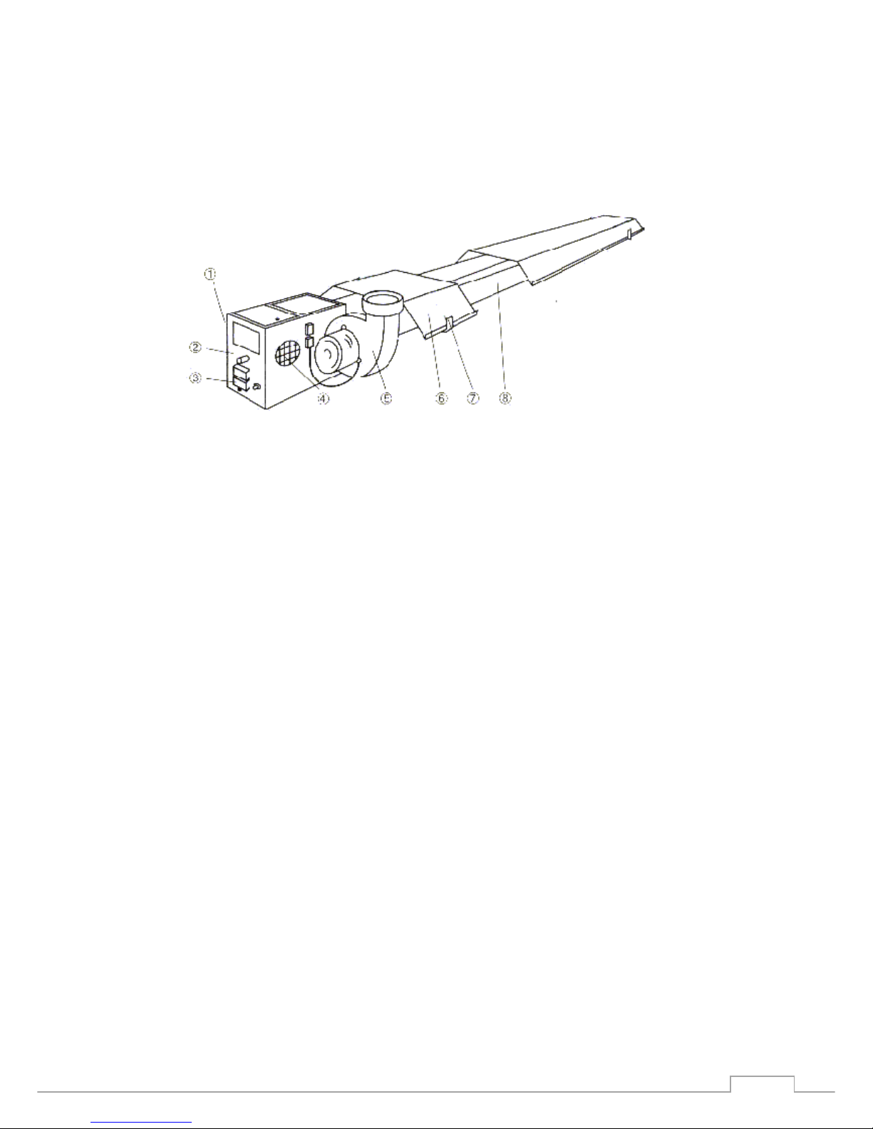
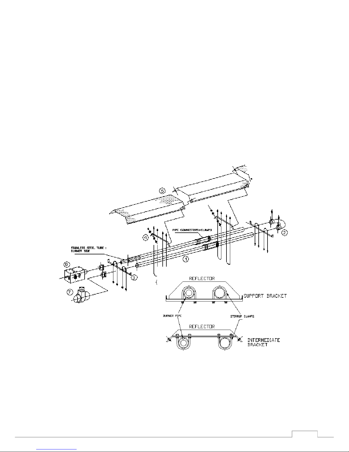
4. Radiant Unit Construction and Assembly.
The gas radiant heaters are constructed from the following main parts:
gas burner, radiant tube, reflector and flue gas fan.
1. Gas Burner 5. Flue gas fan
2. Gas connection 1/2"BSP 6. Reflector
3. Electrical connection 7. Radiant tube support and
(mains and controls plug) mounting bracket
4. Combustion air intake 8. Radiant tube
As delivered, there are the radiant tubes, reflector sections and a carton containing
the following parts: gas burner, flue gas fan, U-bend,pipe connectors (3/9E, 4E and
L versions), support and intermediate brackets, stirrup clamps and reflector screws.
The radiator is assembled as follows - see the drawing which follows and assembly
diagrams.
4.1. Lay the radiant tubes, with both ends free on the appropriate supports,
preferably under the position where it is to be mounted. Note that one end, the
burner end, has an inner stainless steel tube
4.2. Push the U-bend, with the securing screws upwards, onto the tubes until these
are firmly against the shoulders. Tighten the securing screws firmly!
4.3. Place the support brackets on the tubes at both ends and in the middle, place
the stirrup clamps in place and firmly - maintain the distances indicated .
4.4. Lay the intermediate brackets, fasten with the stirrup clamps: first screw the
lower nuts on as far as the end of the thread, insert the stirrup clamps, tighten the
upper nuts.
Important ! After the stirrup clamps are laid in place, the intermediate brackets must
be able to be moved freely on the pipes!

Ray.Red
GAS POWER
STP 035GB – 04-18
8
Remove the protective plastic film from the reflector sections and push them into the
support brackets. Fasten the reflectors to the intermediate brackets with the
provided screws.
If preferred, the reflectors may be fitted after the unit is in place.
4.5. Insert the burner, with the warning lamps downwards, on the pipe until it comes
up against the shoulder. Be sure that the burner is mounted on the pipe with inner
stainless steel tube (look for the inner pipe!). Fasten the clamps.
.
Ray.Red
GAS POWER
STP 035GB – 04-18
9
Ray.Red
GAS POWER
STP 035GB – 04-18
10
Important:
Check the alignment of the burner: The burner axis and the pipe axis must
coincide, misalignment of the burner shortens the life of the pipe! If the mounting is
to be at an angle, the burner must be fitted to the lower pipe and vertically
orientated. Check also that there is a minimum separation between the burner box
and the reflector of 5-10cm.
4.6. Insert the flue gas fan into the free end of pipe until it comes up against the
shoulder, arrange the connection socket horizontally or vertically according to the
flue arrangement, fasten the clamp, plug the motor connection into the socket on the
burner housing.
1.Radiant pipe
2. U-bend
3. Support bracket
4. Intermediate bracket
5. Reflector
6. Gas burner
7. Flue gas fan
8. Stirrup clamps
.

Ray.Red
GAS POWER
STP 035GB – 04-18
11
5. Planning Requirements
5.1 Appliance Positioning
The number and models of radiant heaters will be determined by the heating
requirement (full or partial heating) and the height of installation.
An even distribution of radiation will be achieved when the radiant angles of
neighbouring appliances intersect each other approximately 1.5 - 2.0 m above the
floor. For full heating, the outside walls must also be within the zone of radiation.
The radiation angle from the reflector sides to the floor is approximately 60o.
Dependent on the height of installation and the way the units are suspended, the
following indicative values can be arrived at for the radiant area at floor level:
Radiant heater model
Ray 1 E 2 E 3 E 4 E
Height of installation (m)
- horizontal suspension
min. 4,0 4,0 4,0 5,0
max. 5,0 7,0 9,0 9,0
-angled suspension
: min. 3,0 3,3 3,7 4,5
to 35°
max. 4,0 5,0 5,0 5,5
Radiant area* (m x m)
min. 5 x 5 6 x 7 8 x 10 14x12
with horizontal suspension
max. 8 x 8 11 x 12 15 x 16 16x16
* Indicative values to enable the rough selection of models
5.2 Minimum Clearances
The minimum clearance above and sideways from the reflector is 500 mm when
there are inflammable fittings or material nearby.
This clearance can be reduced by the use of insulation.
Under the radiant tube (within the zone of radiation) there should be on objects or
fittings a distance of 1500 mm.
Further, the general surface temperature of the supporting parts of the building
should not exceed 50oC.
.

Ray.Red
GAS POWER
STP 035GB – 04-18
12
5.3 Controls
The radiant heater can be controlled by an operating switch or by a room thermostat
and, if appropriate, a time switch.
Where the whole space is to be heated use an electronic thermostat with "black
bulb" sensor; it takes account of both air and average radiant temperature.
The setting should be the same as the desired comfort temperature.
5.4
Flue Gas Extraction
Since the radiant heaters are fitted with flue gas fans, the flue gas must be
discharge through the roof or an outside wall.
The maximum length of the 100 mm dia. flue pipe may not exceed 4 m with two
bends.
In case of superior length, the diameter of the flue pipe should be greater (Ø 130).
5.5 Combustion Air
The combustion air will generally be drawn from the room.
If there is insufficient ventilation or if there are corrosive or dangerous vapours or
gases or dust or may possibly arise, the combustion air must be brought from
outside through a fresh air duct.
With an individual gas flue through the outside wall, the total combined length of the
flue gas and fresh air ducting must not be greater than 4 m with two bends.
Planning and realisation must be according to the relevant regulations.
6. Standards, Rules and Regulations
The following standards rules and regulations must be taken into account before and
during the installation:
1. All relevant national and international standards and regulations
2. Building Regulations
3. Any planning requirements
4. Any requirements imposed by the local fire service
5. Any requirements imposed by the Health and Safety Executive or their local
equivalent
6. Any requirements imposed by an insurance company
7. Any requirements imposed by the local gas distribution company

Ray.Red
GAS POWER
STP 035GB – 04-18
13
7. Installation
7.1 Paking, logistic and transport
When the package is delivered to the client, the latter is obliged to control the integrity of the
product.
Control the package an its contents, in case of
damage due to the transport, the client has to
tick damage claim box on the transport
document, this has to be countersigned by the
carrier and a copy has to be sent to Impresind
Srl.
Pay high attention handling the TUB-ONE units during the phases of
downloading from the carrier, logistics and positioning, to avoid damages
to carpentry and to the most delicate components (tubes, fans, etc.).
IMPRESIND SRL DECLINES ANY RESPONSABILITY FOR DAMAGES DUE TO
TRANSPORT, UPLOAD, DOWNLOAD OF THE TUB-ONE UNITS
Ensure that the maximum lifting power of the lifter is adequate to the
products weight.
The product has to be lifted only by qualified personnel.
Pay maximum care in handling the radiant strips while downloading form
the carrier, positioning and the assembling the sections, to avoid damages.
If lifting people the machinery has to be specifically certified and used by
qualified personnel.
IT IS ABSOLUTELY FORBIDDEN TO STAY UNDER THE HANGING LOADS AND
INSIDE THE ACTION AREA OF THE LIFTER

Ray.Red
GAS POWER
STP 035GB – 04-18
14
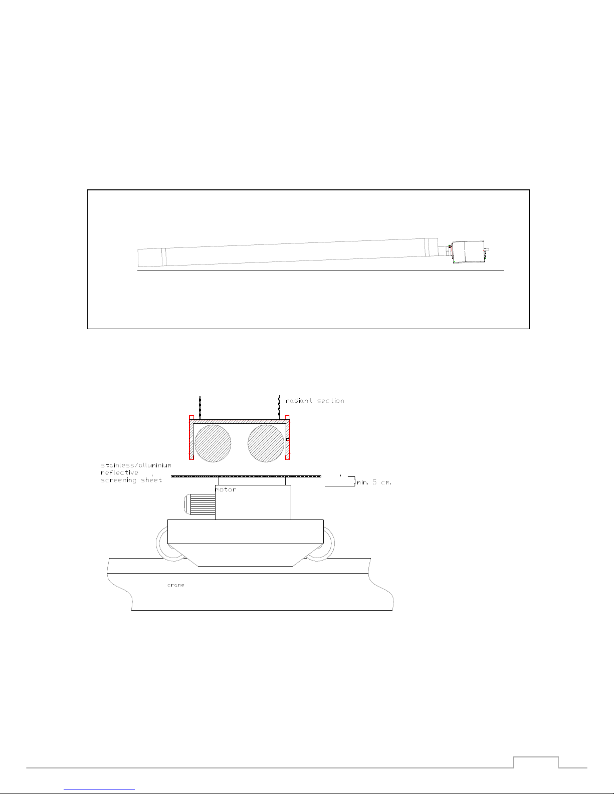
7.2 Suspending the Appliance
Suspend the radiant units in the foreseen place using suitable dimensioned chains,
steel rods or steel ropes or, where appropriate, wall brackets, if possible with a
downwards slope towards the U-bend (or the flue gas fan for the L versions) of up to
25 mm. For the adjustment, use locking devices. Observe the minimum clearances
in Section 5.2.
Ray.Red
GAS POWER
STP 035GB – 04-18
15
Important !
Depth in the direction of the terminal curve: 2.0 ÷ 4 cm. this is necessary in order to
prevent condensation dripping during the initial phase of operation.
View picture below
RADIANT SECTIONS POSITIONED NEAR A CRANE

Ray.Red
GAS POWER
STP 035GB – 04-18
16
7.3 Gas Connection
Check on the appliance plate for the type of gas for which the heater is set. If
necessary, convert to the supply available - see Section 9.
The gas connection must only be made by a qualified installer.
Between the gas connection on the radiant heater (1/2" male BSP) and the gas
supply, must be inserted a flexible metal hose approved for such use and a shut-off
valve (both to be supplied by the installer).
For LPG it is essential that a 37 mbar pressure reducer is installed on the gas
supply.
Important !
Connection pressures in excess of 50 mbar can damage the gas valve.
No excessive force is to be used on the connection pipe.
The connection must be tested for gas tightness and the gas pipe must be emptied
from air.
For the gas pressure supply view the paragraph 3 in this istruction
If the connection is not within these limits, the connection may not be made and the
appliance may not be used.
If the cause of the divergence from these values cannot be corrected by the installer,
then the gas utility or LPG supplier should be notified.

Ray.Red
GAS POWER
STP 035GB – 04-18
17
7.4 Electrical Connection
The electrical connection must be carried out by a qualified electrician in accordance
with applicable regulations - see the circuit diagrams which follow.
The mains connection is by a plug on the radiant unit. It must be connected to a
main switch.
Important !
Ensure that the wiring is phased correctly. A good earth connection is essential for
trouble free operation.
F - 2 amp fuse
CF - Burner controller M - Flue gas fan motor
J5 - Ionisation electrode LV - Stand-by light (green)
PA - Low air pressure cut-out LG - Operating light (yellow)
VG - Gas Valve LR - Failure light (red)
TA - Room thermostat
JT2 - Ignition electrode

Ray.Red
GAS POWER
STP 035GB – 04-18
18
DIAGRAM FOR THE CONN ECTIO N TO THE BUR NER
Model with terminal box with 7 poles
IMPORTANT !
CONNECT THE UNIT AS INDICATED IN THE DIAGRAM
RESPECT THE POLARITY BETWEEN PHASE AND NEUTRAL
FOR SIGNALS:DO NOT USE FILAMENT LAMPS, USE ONLY NEON LAMPS
THE RESET BUTTON IS NECESSARY
“L4” AND “L5” LAMPS ARE NOT NECESSARY BECAUSE THEY ARE ALREADY
PRESENT ON THE BURNER BOX
.

Ray.Red
GAS POWER
STP 035GB – 04-18
19
7.5 Flue Gas Removal and Combustion Air Supply
Install the flue gas removal and, if appropriate, combustion air supply according to
the plans - see also Sections 5.4 and 5.5.
The flue gas pipe must not put a stress on the connection.
Fresh air ducting is to be flange connected to the side of the burner house without
stressing the house.
Fit the flue gas and fresh air pipes at the outside wall with suitable wind and rain
terminals.
8. Start up and settings
The first start up of the unit may only be undertaken by an authorised specialist or by
the manufacturer's customer service.
Important!
Check all connections and screwed joints of the radiant unit for tightness with a
suitable corrosion free spray
8.1 Testing the pressure
Check the type of gas on the appliance plate.
Connect a U-tube manometer through the opening on the rear of the burner (remove
the cover) to the inlet measuring point P1. Start the appliance and note the limit
value.
Connect a U-tube manometer to the outlet measuring point P2, start the appliance.
The jet pressure must agree with the setting shown on the appliance plate.
(see section 3 – technical data).
Eventually set the jet pressure, using the S regulator screw.

Ray.Red
GAS POWER
STP 035GB – 04-18
20
Front sight
Rear sight
8.2 Training to the operator
After start up and settings of the radiant unit, instruct the operator in detail on the
use and maintenance operations. Recommend a service contract.
.
s
P2
P1
Sit Gas Valve
s

Ray.Red
GAS POWER
STP 035GB – 04-18
21
9. Conversion
The conversion may only be undertaken by a qualified expert referring strictly to the
setting data.
Important!
Jet and jet pressure see section 3 ( technical data ).
- Change the burner jet.
- Remove the seals and re-set the pressure regulator S, connecting a U-tube
manometer to measuring point P2 for this.
- After setting, re-seal the pressure regulator S.
- Change the details of the type of gas on the appliance plate.
10. Service
The heating unit should be serviced annually before the start of the heating season.
The service work is only to be undertaken by properly qualified personnel.
It is recommended that a service contract should be taken out.
During the servicing, brush or vacuum the radiant pipes and the inner side of the
reflectors free from dust.
If installed in a particularly dusty environment, as for instance in foundries, this
should be carried out more frequently and at regular intervals.
Note!
Never lean a ladder or other object against the radiant pipes or the reflector.
Before beginning to clean the appliance the gas and electrical supplies must be
disconnected.
The following checks are to be carried out during servicing:
- Checking of the flue gas fan for excessive or unusual noise and any imbalance.
- Verify the cleaning of the flue gas pipe
- Type of gas and jet size; if necessary, clean or replace the jet
- Verify the Gas pressure setting
- Verify the gas connection and gas tightness of the control section

Ray.Red
GAS POWER
STP 035GB – 04-18
22
- Verify the electrical connection
- Verify the functioning of the low air pressure cut-out
- Condition and clearance of the ignition and the ionisation electrodes; if necessary
clean or replace
- Satisfactory operation - yellow operating light illuminates; with a fault, e.g. gas
supply interrupted, - red failure light illuminates.
- Restarts satisfactorily after failure by pressing the reset button
•
Ionisation current during operation should be at least 2,5 µA
•
pre-purge time ca. 20 - 30 seconds
•
Ignition delays ca. 5 seconds.

Ray.Red
GAS POWER
STP 035GB – 04-18
23
Burner and Control Parts
(Burner view, cover removed)
1. Burner cover (removed) 10. Low air pressure cut-out
2. Control cover (removed) 11. Negative pressure measuring point
3. Ignition and ionisation electrodes 12. Motor plug
4. Mixing tube 13. Mains plug
5. Jet 14. Fuse
6. Jet tube 15. Lights
7. Burner controller 16. Gas connection pipe
8. Gas Valve 17. Attachment clamp
9. Double safety solenoid control

Ray.Red
GAS POWER
STP 035GB – 04-18
24
Part 2: OPERATING INSTRUCTIONS
11. Description of Functioning and Use
The infra red radiant heater is switched on by the operating switch and the room
thermostat: the green stand-by light illuminates and remains illuminated.
After ca. 30 seconds pre-purge and if the negative pressure in the radiant tube is
satisfactory, the ignition phase of the burner follows for 5 seconds via the ignition
electrode: the ignition transformer produces high tension discharges in the gas/air
mixture.
The yellow operating light remains illuminated while the appliance is operating
When the flame forms within the time allowed and sufficient ionisation current is
produced, the appliance remains in operation until switched off by the room
thermostat or the operating switch.
If burner ignition does not take place, the appliance switches to failure: the red light
comes on and the yellow light goes out.
By pressing the reset button, a new ignition cycle is initiated, the red failure light
goes out and the yellow light comes on.
Important!
When there is a long break in the operation of the unit (as, for instance, during the
summer) several repeats of the ignition procedure is a means of clearing the gas
piping of air.
12. Suggestions for Energy-Saving Operations
- Control the unit by a room thermostat with black bulb sensor. Night set back to less
than 5oC leads to an extended heating up period and raises the energy
consumption.
- A rise of 1°C over the desired temperature, causes an approximately 6% higher
consumption of energy.
- Large objects, shelving, partition walls etc. which impede the direct radiation, impair
the heat distribution at floor level and force an increase in the temperature setting
(longer operating time, higher energy consumption).
- Heat sensitive or inflammable objects must not be stored in the immediate
proximity of the radiant heater or be exposed directly to the radiation (see sections 2
and 5.2)

Ray.Red
GAS POWER
STP 035GB – 04-18
25
- Dust build ups on the radiant pipes and reflector reduce the radiation and hence
the efficiency (higher energy consumption) - see section 14.
- The correct gas setting and regular servicing reduce the energy consumption. A
service contract is thus to be recommended.

Ray.Red
GAS POWER
STP 035GB – 04-18
26
13. Maintenance of the Unit
Operation
Frequency
Operation
Description
Resolution
Description
Note and/or
Records
Yearly
Check draft and / or
chimney exhaust fumes
state
(not included in the
machine)
Clean exhaust fumes ducts
Yearly
Check air holes in the side
pannel
Clean all air holes
Check there aren
’t objects
near the air holes
Yearly
Check electrical
connections, cabling
status, fan motor
absorption, and
devices
of safety
(not included in the
machine but also
related to it)
Substitution elettrical
wiring ora component
Check with appropriate
elettrical istrument
Yearly
Check, oxidation, wear
and flame ignition and
burner torch damage
With
cases easy oxidation
sanding the damage
components. With cases
hard oxidation substitution
damage components
If the burner is blocked
often, or there is a bad
flame relief, there are
symptoms of possible
oxidation of the candle
(especially if installed in
wetlands)
Yearly
Check the correct pressure
setting and electric valve
setting
Execute a correct setting if
possible. If not possible
substitution damage
components
Symptom of incorrect
calibration is the relief of
ONX data out of the
ordinary
(relief from point
of pick in the
smoke fireplace)
Yearly
Check for leaks between
the various
modules via nips/joints
Substitution damage
nips/joints
Symptom of incorrect
holding between modules
is an incorrect and
repeated intervention
of the pressure switch
(which does not
can detect a proper
depression in the plant)

Ray.Red
GAS POWER
STP 035GB – 04-18
27
14. If the Unit Does Not Operate Properly
Any time there is a failure, first check:
- Is there electric power?
- Is the operating switch On and the room thermostat correctly set - is the green
stand-by light on the unit illuminated?
- Is gas available?
If the unit does not operate and the failure light is illuminated, proceed as follows:
- Press the reset button on the unit or the control panel to restart.
- Observe the sequence of the start-up and select the type of problem from the list
which follows.
If the problem, in one of the following cases, cannot be solved by the operator,
contact the contracted servicing organisation.
.
Possible Problems
A. The green stand-by light on the unit does not illuminate.
Mains wire or room thermostat wire or one of their connections are broken.
B. The green stand-by light is illuminated , the flue gas fan does not run.
The motor connection is faulty (loose connection)/the motor or its condenser is
faulty.
C. The flue gas fan runs, the ignition sequence does not follow in 30 seconds yellow operating lamp not illuminated.
Air pressure cut-out does not close:
Setting incorrect / connecting hose plugged / electrical connection interrupted (loose
connection) / cutout defective.
D. The flue gas fan runs, ignition sequence starts after 30 seconds - yellow
operating light remains unilluminated, unit goes to failure - red failure light
illuminated.
Gas Valve does not open:
Electric connection interrupted (loose connection) / magnetic coil defective.

Ray.Red
GAS POWER
STP 035GB – 04-18
28
E. The flue gas fan runs, ignition sequence starts after 30 seconds - yellow operating
light illuminates, unit goes to failure - red failure light illuminated.
1. Air in the gas line:
repeat the start up several times, flush the gas line free of air.
2. No flame forms:
Incorrect gap between the ignition electrodes / ignition cable or its connections
broken / ignition transformer in the burner controller defective.
3. Flame forms but no or insufficient ionisation current:
Ionisation electrode incorrectly positioned / ionisation cable or its connections
broken.
Inclination 2 ÷ 4 cm
Maximum inclination in case of installation of the unit to the wall: 30°
Ray.Red
GAS POWER
STP 035GB – 04-18
29
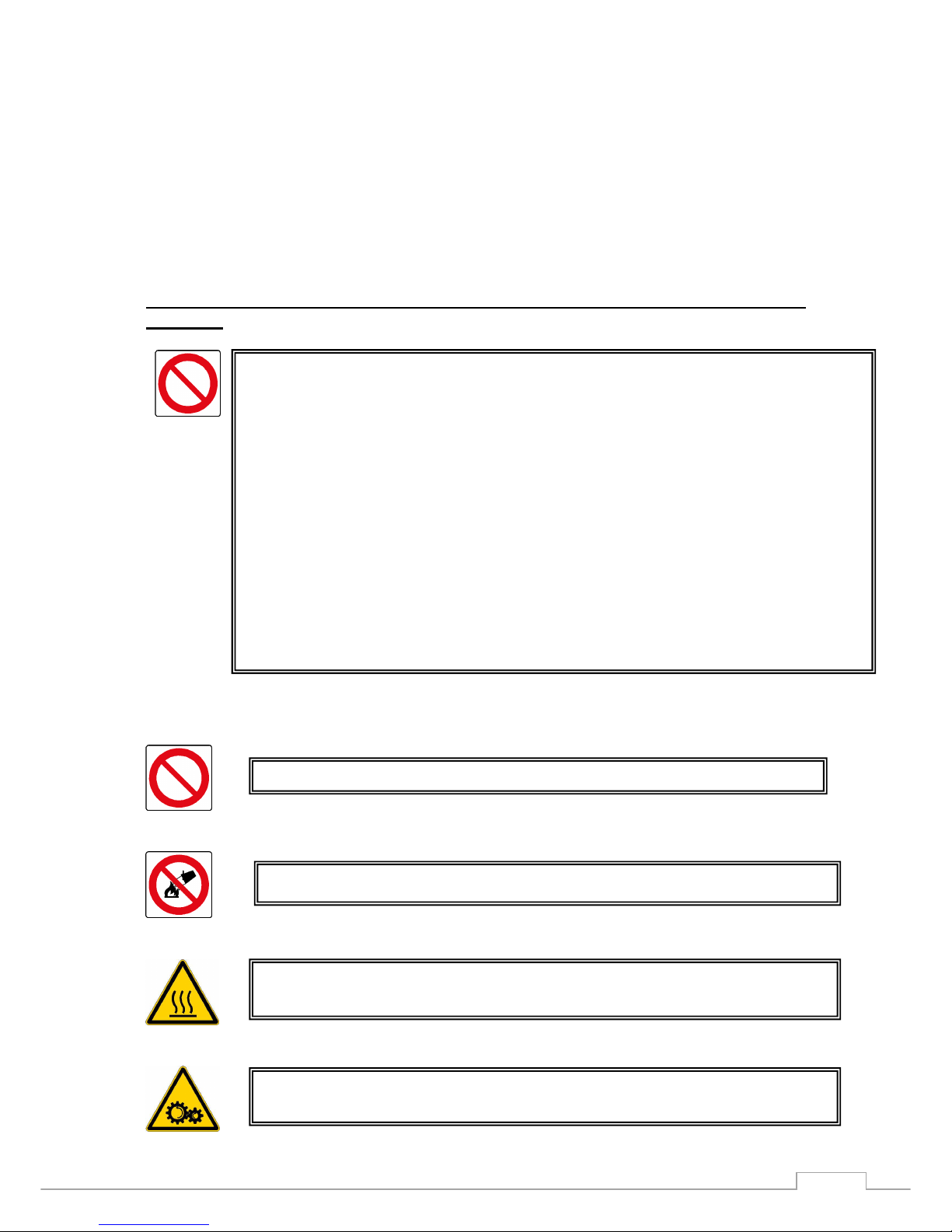
Part 3: CAUTIONS AND RESTRICTIONS
15. Improper Use
The unit can’t be used for different scopes than the one stated in the paragraph 11 of
this guide.
IT IS ABSOLUTELY FORBIDDEN TO INSTALL THIS PRODUCT IN EXPLOSIVE
ENVIRONMENTS AND/OR ENVIRONMENTS CONTAINING HIGHLY INFLAMMABLE
MATERIALS.
IT IS ABSOLUTELY PROHIBITED TO INSTALL THE APPLIANCES IN LOCALS NOT ADEQUATELY
WASTE
IT IS ABSOLUTELY PROHIBITED TO OVERLOAD A BREEDER BOX OF ALL WEIGHT
IT IS ABSOLUTELY PROHIBITED TO AGGRAPPY AND / OR SUPPORT TO THE BOX-BURNER,
WHICH TO THE VARIOUS RADIANT MODULES (even if it is off and with a surface temperature
equal to that ambient)
DURING HEATER OPERATION, DO NOT TOUCH THE TUBES – DANGER OF
BURNS.
DURING HEATER OPERATION, DO NOT TOUCH THE FLUE FAN – DANGER
FROM MOVING PARTS.
IT IS ABSOLUTELY FORBIDDEN TO ESTINGUISH FIRES WITH WATER
IT IS ABSOLUTELY FORBIDDEN TO MODIFY THE INTERNAL WIRING

Ray.Red
GAS POWER
STP 035GB – 04-18
30
16. Dismantling
In case of dismantling or alienation of the system, it is necessary to recover all the materials
and send them to the respective collection centres, possibly referring to specialised
companies.
The dismantling of the system has to be done by specialised personnel with
correct instruments and personal protection devices.
Do not smoke and not use free flames.

Ray.Red
GAS POWER
STP 035GB – 04-18
31
Impresind Srl Via 1° Maggio 24, Gorgonzola (Milano, Italy)
℡ +39 02 95741932 +39 02 95740637 impresind@impresind.it
www.impresind.it
 Loading...