

Page 1

xArray/xSpan Installation and Operations Guide
Version 5.8.0
Copyright © 2012 - 2016 Impinj, Inc. All rights reserved
http://www.impinj.com
Impinj, Octane, Speedway, and xArray are either registered trademarks or trademarks of Impinj,
Inc. Visit www.impinj.com/trademarks for additional information about Impinj trademarks.
Page 2

xArray/xSpan Instal lation and Operations Guide
Contents
1 Requirements, Certications, and Warnings 4
1.1 Products Covered by this Guide . . . . . . . . . . . . . . . . . . . . . . . . . . . . . 4
1.2 Federal Communications Commission (FCC) Compliance . . . . . . . . . . . . . . . 5
1.3 CE Marking and European Economic Area (EEA) . . . . . . . . . . . . . . . . . . . 6
1.4 National Communications Commission (NCC - Taiwan) Administrative Rules for
Low-power Radio-Frequency Devices . . . . . . . . . . . . . . . . . . . . . . . . . . 6
1.5 Environmental Requirements . . . . . . . . . . . . . . . . . . . . . . . . . . . . . . 7
1.6 Power Requirements . . . . . . . . . . . . . . . . . . . . . . . . . . . . . . . . . . . 7
1.7 Before You Begin . . . . . . . . . . . . . . . . . . . . . . . . . . . . . . . . . . . . . 7
1.8 About This Guide . . . . . . . . . . . . . . . . . . . . . . . . . . . . . . . . . . . . 8
1.8.1 Intended Audience . . . . . . . . . . . . . . . . . . . . . . . . . . . . . . . . 8
1.8.2 Other Documents of Interest . . . . . . . . . . . . . . . . . . . . . . . . . . 8
2 Introduction 10
3 xArray Product Tour 11
3.1 xArray Status Lights . . . . . . . . . . . . . . . . . . . . . . . . . . . . . . . . . . . 12
3.2 Mounting the xArray using Detachable Mounting Plate . . . . . . . . . . . . . . . . 14
4 xSpan Product Tour 18
4.1 Mounting the xSpan using Detachable Mounting Plate . . . . . . . . . . . . . . . . 19
5 Powering and Connecting 23
5.1 Supplying Power . . . . . . . . . . . . . . . . . . . . . . . . . . . . . . . . . . . . . 23
5.2 Connecting to a TCP/IP Network . . . . . . . . . . . . . . . . . . . . . . . . . . . . 24
5.3 Verifying Network Connectivity . . . . . . . . . . . . . . . . . . . . . . . . . . . . . 25
5.4 Connect using Serial Console Port . . . . . . . . . . . . . . . . . . . . . . . . . . . . 26
version 5.8.0 2
Page 3

xArray/xSpan Instal lation and Operations Guide
6 Using xArray/xSpan with ItemTest 29
6.1 Download ItemTest . . . . . . . . . . . . . . . . . . . . . . . . . . . . . . . . . . . . 29
6.2 Install and Launch ItemTest . . . . . . . . . . . . . . . . . . . . . . . . . . . . . . . 29
6.3 Connect and Congure the Gateway . . . . . . . . . . . . . . . . . . . . . . . . . . 30
6.4 Run Inventory or Location Tests with ItemTest . . . . . . . . . . . . . . . . . . . . 33
6.5 Run Direction Tests with ItemTest . . . . . . . . . . . . . . . . . . . . . . . . . . . 36
7 Conguring and Monitoring 40
7.1 Conguring the Gateway . . . . . . . . . . . . . . . . . . . . . . . . . . . . . . . . . 40
7.1.1 Device Conguration . . . . . . . . . . . . . . . . . . . . . . . . . . . . . . . 40
7.1.2 Using RShell to Congure Network Settings . . . . . . . . . . . . . . . . . . 40
7.1.3 RF Conguration . . . . . . . . . . . . . . . . . . . . . . . . . . . . . . . . . 41
7.2 Monitoring . . . . . . . . . . . . . . . . . . . . . . . . . . . . . . . . . . . . . . . . 42
7.2.1 Viewing Network Parameters and Statistics . . . . . . . . . . . . . . . . . . 42
7.2.2 Viewing RFID Parameters and Statistics . . . . . . . . . . . . . . . . . . . . 43
7.2.3 Conguring and Viewing Logs . . . . . . . . . . . . . . . . . . . . . . . . . . 44
7.2.4 Viewing the State of the Gateway Device . . . . . . . . . . . . . . . . . . . 45
8 Upgrading the Gateway Firmware 46
8.1 A Brief Overview of the Firmware . . . . . . . . . . . . . . . . . . . . . . . . . . . . 46
8.2 Upgrading the Firmware . . . . . . . . . . . . . . . . . . . . . . . . . . . . . . . . . 47
8.2.1 Upgrading the Firmware using RShell . . . . . . . . . . . . . . . . . . . . . 47
8.2.2 Upgrading the Firmware with a USB Drive . . . . . . . . . . . . . . . . . . 48
8.2.3 Upgrading the rmware through the Impinj Management Web UI . . . . . . 49
8.2.4 Reverting to the Previous Image . . . . . . . . . . . . . . . . . . . . . . . . 51
9 Troubleshooting 52
9.1 Impinj Support Information . . . . . . . . . . . . . . . . . . . . . . . . . . . . . . . 52
9.2 Returning to the Default Conguration . . . . . . . . . . . . . . . . . . . . . . . . . 52
9.3 Submitting Diagnostic Data for Analysis by Impinj Technical Support . . . . . . . . 55
10 Document Revision History 56
version 5.8.0 3
Page 4

xArray/xSpan Instal lation and Operations Guide
1 Requirements, Certications, and Warnings
1.1 Products Covered by this Guide
This guide pertains to Impinj xArray/xSpan Gateways with the following part numbers:
Table 1.1: xArray Gateway Part Numbers
Gateway Communication Code Part Number
xArray FCC IPJ-REV-R680-USA
xArray ETSI IPJ-REV-R680-EU1
xArray Japan IPJ-REV-R680-JP2
xArray GX1 IPJ-REV-R680-GX1
xArray GX2 IPJ-REV-R680-GX2
xArray GX3 IPJ-REV-R680-GX3
Table 1.2: xSpan Gateway Part Numbers
Gateway Communication Code Part Number
xSpan FCC IPJ-REV-R660-USA
xSpan ETSI IPJ-REV-R660-EU1
xSpan Japan IPJ-REV-R660-JP2
xSpan GX1 IPJ-REV-R660-GX1
xSpan GX2 IPJ-REV-R660-GX2
xSpan GX3 IPJ-REV-R660-GX3
version 5.8.0 4
Page 5

xArray/xSpan Instal lation and Operations Guide
1.2 Federal Communications Commission (FCC) Compliance
This equipment was tested and complies with the limits for a Class B digital device, pursuant
to Part 15 of the FCC Rules. These limits are designed to provide reasonable protection against
harmful interference in a commercial environment. This equipment generates, uses, and can radiate
radio frequency energy. If not installed and used in accordance with the instructions, the equipment
may cause harmful interference to radio communications. However, there is no guarantee that
interference will not occur in a particular installation and cause harmful interference to radio
or television reception. To determine if this equipment causes harmful interference to radio or
television reception, turn the equipment o and on. You are encouraged to try to correct the
interference by one or more of the following:
• Reorient or relocate the receiving antenna.
• Increase the separation between the equipment and receiver.
• Consult the dealer or a qualied radio/TV technician for assistance.
Per FCC 15.19(a)(3) and (a)(4)
This device complies with part 15 of the FCC Rules. Operation is subject to the
following two conditions:
(1) This device may not cause harmful interference.
(2) This device must accept any interference received, including interference that may
cause undesired operation.
Per FCC 15.21
Changes or modications not expressly approved by the party responsible for compliance could void the user’s authority to operate the equipment.
Minimum Separation Distance
This device has been evaluated for compliance with FCC and IC RF exposure
limits in a mobile conguration. At least 34 cm of separation distance between the
device and the user’s body must be maintained at all times. This device must not be
used with any other antenna or transmitter that has not been approved to operate in
conjunction with this device.
version 5.8.0 5
Page 6

xArray/xSpan Instal lation and Operations Guide
Industry Canada (IC) Compliance
Operation is subject to the following two
conditions:
1. This device may not cause interference.
2. This device must accept any
interference, including interference
that may cause undesired operation
of the device.
The term “IC” before the radio certication
number only signies that Industry of
Canada
technical specications were met.
Industrie Canada (IC) Conformité
Son fonctionnement est soumis aux deux
conditions suivantes:
1. Cet appareil ne doit pas
provoquer d’interférences.
2. Cet appareil doit accepter toute
interférence, y compris celles
pouvant causer un mauvais
fonctionnement de l’appareil.
L’expression “IC” avant le numéro
de certication radio signie seulement que
l’industrie des spécications techniques
Canada ont été respectées.
1.3 CE Marking and European Economic Area (EEA)
RFID devices designed for use throughout the EEA must have a maximum radiated transmit power
of 2W ERP in the frequency range of 865.6-867.6 MHz. For other EEA restrictions on RFID device
use, refer to the Impinj Declaration of Conformity (DoC) located at support.impinj.com.
1.4 National Communications Commission (NCC - Taiwan) Administrative Rules for Low-power Radio-Frequency Devices
This device complies with the following items of NCC related rules:
Article 12
Without permission granted by the NCC, any company, enterprise, or user is not allowed to change
frequency, enhance transmitting power or alter original characteristics as well as performance to
approved low-power radio frequency devices.
Article 14
The low-power radio frequency devices shall not inuence aircraft security and interfere with legal
communications. If found, the user shall cease operating immediately until no interference is
achieved.The said legal communications means radio communications is operated in compliance
with the Telecommunications Act.The low-power radio frequency devices must be susceptible with
the interference from legal communication or ISM radio wave radiated devices.
version 5.8.0 6
Page 7

xArray/xSpan Instal lation and Operations Guide
1.5 Environmental Requirements
Operating temperature: -20 to 50C (non-condensing)
1.6 Power Requirements
Warning: This product may be
powered by an IEEE 802.3af (Power over
Ethernet)
compliant power source that is certied by
the appropriate agencies, or with a
listed/certied power supply marked LPS or
Class 2, with 24Vdc output, rated minimum
2.5A.
The use of alternative power supply will
invalidate any approval given to this device
and may be dangerous.
When supplied by the Impinj-approved listed/certied power supply model number IPJ-A2002-000,
the available AC power cords are:
• IPJ-A2051-USA (for North America)
• IPJ-A2051-EU1 (for European Union)
• IPJ-A2051-JPN (for Japan)
• IPJ-A2051-BRA (for Brazil)
• IPJ-A2051-CHN (for China)
Attention: Ce produit peut être
alimenté par un IEEE 802.3af (Power over
Ethernet) source d’alimentation conforme
qui
est certié par les organismes appropriés,
ou avec une alimentation inscrite/certié
LPS ou classe 2 marquée, avec une sortie
24V,
2,5A nominal minimal. L’utilisation d’une
autre alimentation annule toute autorisation
liée à cet appareil et peut être dangereuse.
1.7 Before You Begin
version 5.8.0 7
Page 8

xArray/xSpan Instal lation and Operations Guide
Warning: Please read this document in
its entirety before operating the
xArray/xSpan
Gateway, as serious personal injury
or equipment damage may result from
improper use. Unauthorized opening of the
xArray/xSpan Gateway enclosure voids the
warranty.
Avertissement: S’il vous plaît lire ce
document dans son intégralité avant
d’utiliser le xArray/xSpan Gateway,
comme des blessures graves ou des
dommages matériels peuvent résulter d’une
mauvaise utilization. Ouverture non
autorisée du lecteur xArray/xSpan Gateway
boîtier annule la garantie.
1.8 About This Guide
This guide provides instructions for installing, connecting, conguring, operating, upgrading, and
troubleshooting the xArray/xSpan Gateway. To shorten the length of this guide, the content
focuses on the installation and operation of one xArray/xSpan.
1.8.1 Intended Audience
The intended audience for this guide is anyone installing an xArray/xSpan. The assumed primary
users of this guide are systems engineers and IT personnel with experience and basic knowledge
of:
• Software development
• Hardware systems integration
• Network connectivity
This guide also assumes that the user has a high-level understanding of RFID, RFID systems
management, and a basic familiarity with the EPCglobal Gen 2 specication, which can be found
at http://www.gs1.org/gsmp/kc/epcglobal/uhfc1g2.
1.8.2 Other Documents of Interest
This guide is part of a larger documentation set that supports xArray/xSpan as follows:
• LTK Programmer’s Guide provides software engineers with guidelines and best practices for
working with the Low Level Reader Protocol (LLRP) Toolkit. Software engineers can also
access language-specic reference guides and sample applications illustrating the scenarios
discussed in the Programmer’s Guide.
version 5.8.0 8
Page 9

xArray/xSpan Instal lation and Operations Guide
• Octane LLRP is intended for software engineers and describes the LLRP capabilities supported by xArray and xSpan, which includes Impinj’s custom LLRP extensions.
• RShell Reference Manual describes the syntax and command language for the xArray/xSpan
RShell console.
• Octane SNMP Guide provides monitoring and reference information for working with the
SNMP MIBs.
• Firmware Upgrade Reference Manual includes detailed procedures, reference information for
upgrading rmware installed on Impinj Gateway products, and procedures for creating a
metale to automate upgrading of multiple devices.
• Impinj Reader and Gateway Embedded Developer’s Guide provides a description of the Speed-
way platform and a view of its architecture for software engineers designing custom application software for the Reader.
version 5.8.0 9
Page 10

xArray/xSpan Instal lation and Operations Guide
2 Introduction
The xArray/xSpan Gateways are xed infrastructure RFID reader systems that provides alwayson, wide-area monitoring of RAIN RFID tagged items (http://www.rainrfid.org). The xArray/xSpan Gateways are designed for large-scale item-level applications in many industries. The
xArray provides real-time Item Intelligence events, including each item’s identity, location, and
authenticity. The xSpan’s small size is optimal for mounting on walls or in gateways to monitor
tag movement through doors or portals.
Key features and capabilities of your new Impinj RFID Gateway include:
• A single xArray can monitor up to 1,500 ft2(139 m2) using Monza R6 based tags (1,000 ft
(93 m2) for xSpan).
• Intelligent item locating using xArray with 5 ft (1.5 m) or better spatial resolution of (x,y)
location.
• Low prole design ts into standard ceiling tile grid and blends into decor.
• Maximum transmit power and performance is achieved by using IEEE 802.3af PoE. There
is no need for optional AC to DC power module.
• Easy programming using Octane SDK, LLRP and Impinj extensions. Either Gateway contains a SpeedwayR RFID reader that allows you to use all of the same software tools and
LLRP API, with additional extensions specic to xArray/xSpan.
2
version 5.8.0 10
Page 11
xArray/xSpan Instal lation and Operations Guide
3 xArray Product Tour
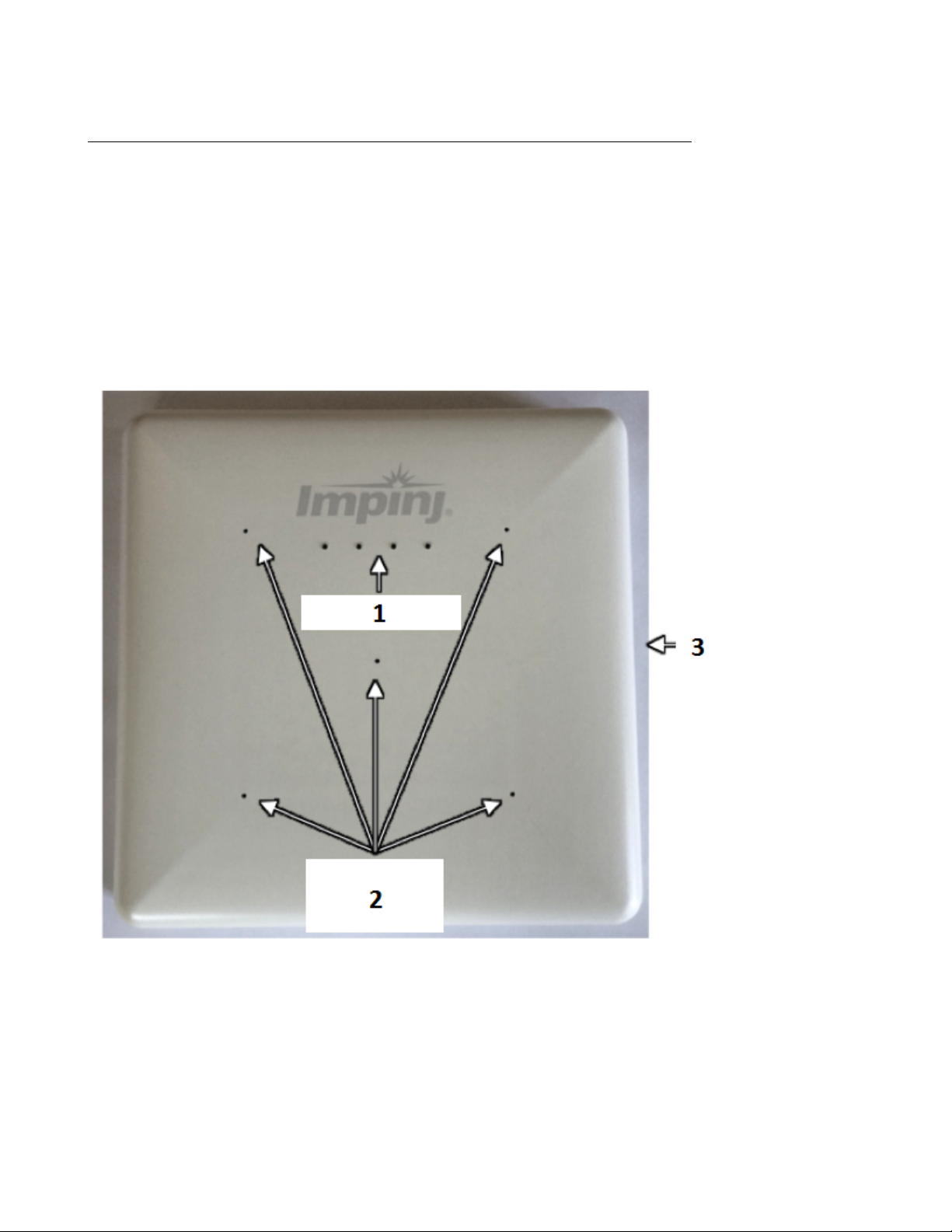
The xArray Gateway radiates RF energy from the radome side, as shown in Figure 3.1. This
plastic cover protects the phased array antenna elements. Drainage holes in the radome are one
design element that allows xArray to provide a IEC IP52 level of water protection. On the side
of the radome is a large label with the last 6 octets of the xArray Ethernet MAC address. This
label is designed to be visible from below when the xArray is mounted overhead, which allows easy
identication.
1. LED Lights
2. Drainage Holes
3. Mounting Clip
Figure 3.1 Radome Side View of xArray
version 5.8.0 11
Page 12
xArray/xSpan Instal lation and Operations Guide
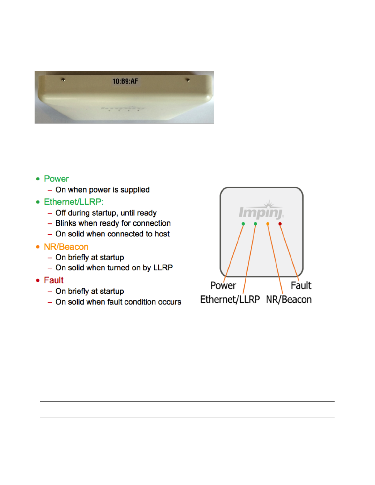
Figure 3.2 Side View Showing MAC Address
The four LEDs that are visible from the radome side help you identify the operation state of
the xArray. Figure 3.3 summarizes what each LED signies during boot, operation, and fault
conditions. The xArray Gateway has four LEDs to indicate operational status, their position.
Figure 3.3 LED Light Behavior
3.1 xArray Status Lights
Each LED has its own blink patterns to convey status to the user. Table 3.1 documents the dened
patterns for the xArray Ethernet/LLRP LED. Table 3.2 documents the dened patterns for the
xArray NR/Beacon LED. Table 3.3 documents the dened patters for the xArray Fault LED.
Table 3.1 xArray Ethernet/LLRP LED
LED State xArray State
OFF During startup
Blinking (GREEN) Ready for an LLRP host connection
version 5.8.0 12
Page 13

xArray/xSpan Instal lation and Operations Guide
LED State xArray State
Solid (GREEN) LLRP host connected
Table 3.2 xArray NR/Beacon LED
LED State xArray State
Blink (ORANGE) Briey during startup
OFF (Default)
ON (ORANGE) When turned ON by LLRP command
Table 3.3 xArray Fault LED
LED State xArray State
Blink (RED) Briey during startup
OFF Normal (no faults)
ON (RED) Fault condition occurred
Table 3.4 xArray Operations and Associated LED Behavior
xArray Operation LED Expected Behavior
Power (power on),
normal
completion
Ethernet/LLRP
normal
completion
NR/Beacon Programmable light NR/Beacon
Fault Failure Fault
Power applied,
attempting to start boot
code
LLRP Connection Eth/LLRP
Power
Status
Status
Status
Status
Solid red
O
Solid red
O
Solid red
O
Solid red
O
version 5.8.0 13
Page 14

xArray/xSpan Instal lation and Operations Guide
3.2 Mounting the xArray using Detachable Mounting Plate
The mounting side of xArray is all metal, which allows the mounting to be in contact with Environmental Air Handling Space (EAHS), in accordance with Section 300-22(c) of the National
Electric Code. Figure 3.4 shows the xArray rear mounting side with and without the detachable
mounting plate.
1. Mounting Holes
2. Mounting Clip
3. Labels
4. Mounting Plate
5. Hinges
6. Gaskets
7. Electrical Connections
Figure 3.4 Mounting (Rear) Side of xArray
The xArray is designed to have two mounting congurations, which are described in this section.
Mounting Conguration 1
version 5.8.0 14
Page 15
xArray/xSpan Instal lation and Operations Guide
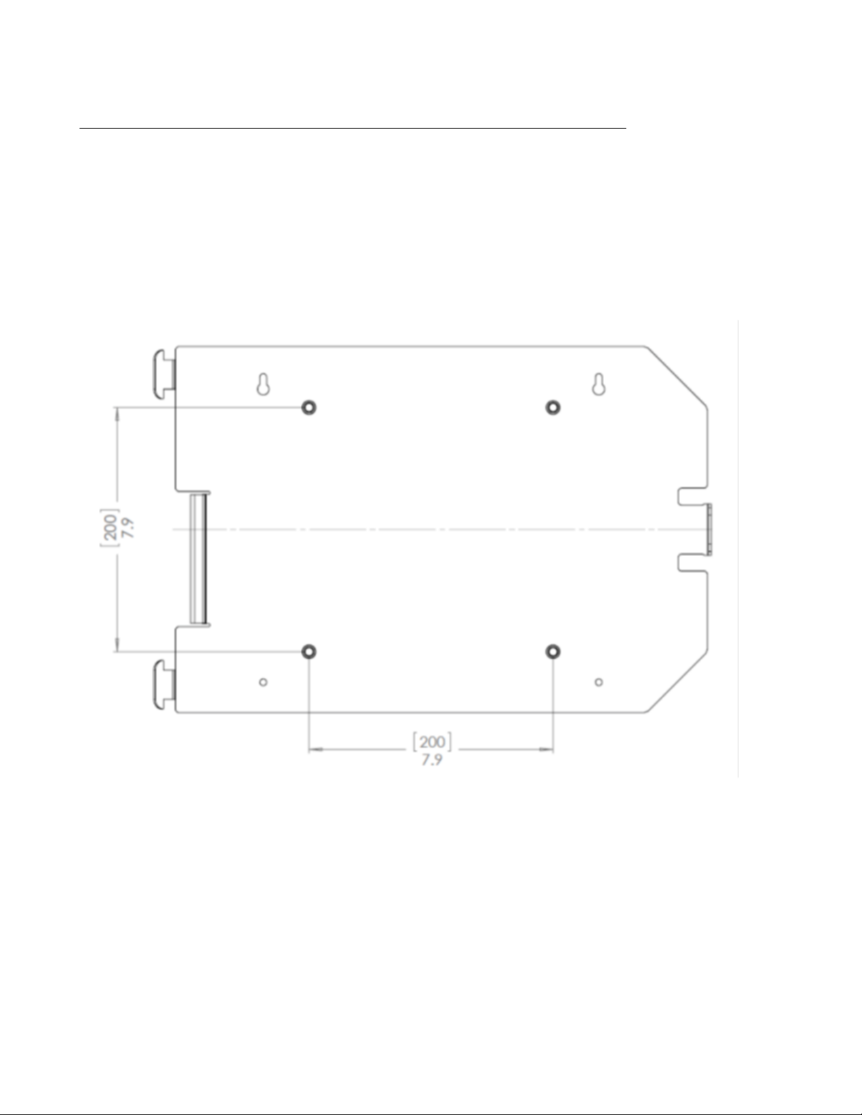
Conguration 1 requires the xArray mount plate to be attached to a Vesa 200 mm mount. The
threaded inserts are designed to hold a M6 bolt. The equation below lists the minimum and
maximum bolt length for your setup.
• Bolt Length Minimum = 7.6 mm + Thickness of Vesa Mount
• Bolt Length Maximum = 12.0 mm + Thickness of Vesa Mount
Figure 3.5 Mounting Conguration 1 for xArray
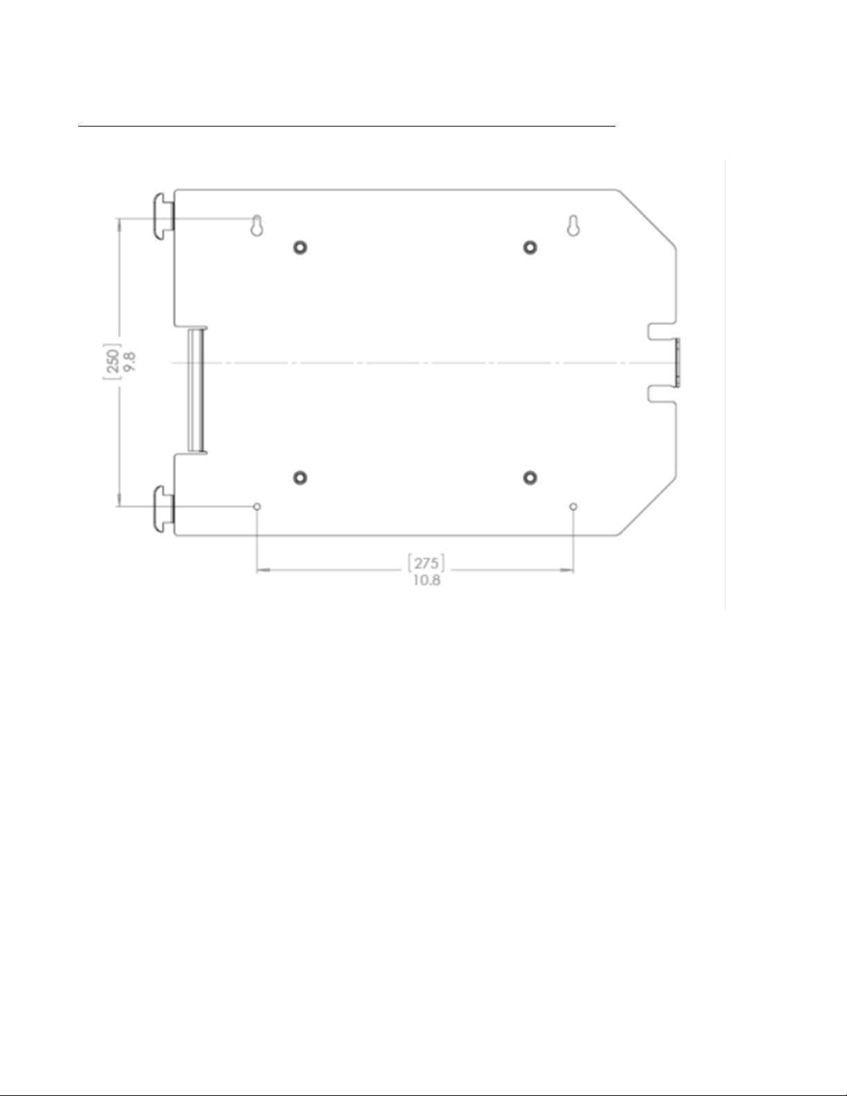
Mounting Conguration 2
Conguration 2 allows you to bolt the xArray mount plate to any structure. The clearance holes
in the mount plate (shown below) can accommodate a M5 Bolt (Metric) or a #10 Bolt (SAE).
version 5.8.0 15
Page 16
xArray/xSpan Instal lation and Operations Guide
Figure 3.6 xArray Mounting Conguration 2
Note: The mounting plate CAD drawing is available for download on the Impinj support portal
at support.impinj.com.
After you have completed the mounting conguration that you want to use, complete the following
tasks:
• After the mounting plate is securely attached to the ceiling, hang the xArray using the hinges.
• In this hanging position, the Ethernet and +24V power (if used instead of POE) cables can
be attached as shown in gure 3.7.
• Rotate the xArray into nal position against the mounting plate, and securely lock it into
position using the mounting clip.
version 5.8.0 16
Page 17

xArray/xSpan Instal lation and Operations Guide
1. Power 24V, 1A
2. PoE Ethernet
3. USB Device (note: Usage not required for normal functionality)
4. USB Host (note: Used for software updates via USB thumb drive)
5. Console (note: Not intended for customer use.)
Figure 3.7 Electrical and Network Connections for xArray
version 5.8.0 17
Page 18

xArray/xSpan Instal lation and Operations Guide
4 xSpan Product Tour
The xSpan Gateway radiates RF energy from the radome side, as shown in Figure 4.1.
1. LED Light
Figure 4.1 LED Location of xSpan
The single multi-color LED is positioned on one side of xSpan, allowing easy viewing when mounted
overhead or on a wall. Figure 4.2 summarizes LED operation during boot, operation, and fault
conditions.
version 5.8.0 18
Page 19

xArray/xSpan Instal lation and Operations Guide
Figure 4.2 LED Light Behavior
4.1 Mounting the xSpan using Detachable Mounting Plate
xSpan provides a detachable mounting plate for overhead or wall mounting options. The mounting
plate is designed to have two mounting congurations, which are described in this section.
Mounting Conguration 1
Conguration 1 requires the xSpan mount plate to attach to a Vesa 75 mm mount. xSpan is
supplied with mounting screws.
version 5.8.0 19
Page 20

xArray/xSpan Instal lation and Operations Guide
Figure 4.3 Mounting Conguration 1 for xSpan
Mounting Conguration 2
Conguration 2 allows you to bolt the xSpan mount plate to any structure. The clearance holes
in the plate can accommodate a M4 (Metric) or #8 Bolt (SAE).
version 5.8.0 20
Page 21

xArray/xSpan Instal lation and Operations Guide
Figure 4.4 Mounting Conguration 2 for xSpan
1. Power 24V, 1A
version 5.8.0 21
Page 22

xArray/xSpan Instal lation and Operations Guide
2. PoE Ethernet
3. USB Device (note: Usage not required for normal functionality.)
4. USB Host (note: Used for software updates via USB thumb drive.)
5. Console (note: Not intended for customer use.)
Figure 4.5 Electrical and Network Connections for xSpan
version 5.8.0 22
Page 23

xArray/xSpan Instal lation and Operations Guide
5 Powering and Connecting
This section describes how to provide power and establish network connectivity to the xArray/xSpan Gateways.
5.1 Supplying Power
You have two choices for powering the Gateway products:
• IEEE 802.3af (Power over Ethernet) compliant source
• Listed/certied power supply, marked LPS or Class 2, with 24Vdc output, rated minimum
2.5A
Note: xArray/xSpan operates at the Class 3 limit for POE power, and requires that the maximum
resistance of the Ethernet cable is 10 Ohms or less (for 100 meter length cable). For a list of cables
that meet xArray/xSpan requirements, see Table 5.1.
Table 5.1 Cat 5e/6 Cable That Meets Requirements
Cable Description Product Information
100 meter cable
< 10 Ohm
50 meter cable
< 10 Ohm
With either option, the boot sequence begins when power is supplied to the Gateway. This sequence
typically completes within 30 seconds. Once the boot sequence nishes, the Gateway accepts
commands, but not before. The Power and Status LEDs on the Gateway alert you of the status.
• http://belkinbusiness.com/products/
a7j304-1000-blu-cat5e-stranded-bulk-cable-4pr24awg-1000-blue
• http://www.southwire.com/ProductCatalog/
XTEInterfaceServlet?contentKey=prodcatsheetcat5e
• http://resources.tessco.com/attachments/516583_
4656914_10_5EN5_BLUE_CPK.aspx.pdf
• http://www.alphawire.com/en/Products/Cable/
Xtra-Guard-Performance-Cable/
Xtra-Guard-Industrial-Ethernet/76020
• http://www.alphawire.com/en/Products/Cable/
Xtra-Guard-Performance-Cable/
Xtra-Guard-Industrial-Ethernet/760
• http://www.farnell.com/datasheets/1311844.pdf
version 5.8.0 23
Page 24

xArray/xSpan Instal lation and Operations Guide
Note, on Cisco Catalyst series switches the Ethernet POE port will automatically disable itself if
the reader has a listed/certied power supply connected. In this situation, the Cisco port must be
set to POE = “never”, using the following Cisco conguration commands.
In this example slot 5, port 2 is being set to POE = “never”.
Switch# congure terminal
Switch(cong)# interface fastethernet 5/2
Switch(cong-if)# power inline never
Switch(cong-if)# end
Switch#
! Important: We recommend that you do not connect both a POE and a listed/certied
power supply to xArray/xSpan. If the Gateway device is receiving power via PoE and detects
that an listed/certied power supply has been connected, the Gateway reboots and switches to
the listed/certied power supply source. If, however, the Gateway is receiving power via an
listed/certied power supply and detects the connection to a PoE-enabled network switch, nothing changes. The Gateway continues to receive power from the listed/certied power supply. The
listed/certied power supply always takes precedence over PoE because the listed/certied power
supply is capable of higher power if both sources are connected.
5.2 Connecting to a TCP/IP Network
The xArray/xSpan internal processor runs Linux OS, which oers robust network support. When
you want to establish TCP/IP network connectivity for deployment or out-of-box evaluation you
have a range of options, including:
• Either Gateway by default are congured to use DHCP. The default host name is xarrayXX-XX-XX or xspan-XX-XX-XX, where XX-XX-XX is the last three bytes of the Gateway’s
MAC address. The large label on the side of the xArray radome (optional on xSpan), provides
these three bytes. Alternately, you can read the MAC address directly from the product label
on the mounting side of the Gateway.
• If you don’t have a DHCP server, OR when the PC is connected directly to the device via
Ethernet cable, the Gateway defaults to a xed IP address, 169.254.1.1. If this address is
not available, the device then randomly selects a xed IP address in the 169.254.xxx.xxx
link local address range.
• You can congure xArray/xSpan to a xed IP address. This option requires conguration
via SSH session over TCP/IP, or a serial connection via console port in order to access
xArray/xSpan’s command line interface (Rshell). For more information about using RShell
to congure network settings, see section 5.1.2.
version 5.8.0 24
Page 25

xArray/xSpan Instal lation and Operations Guide
5.3 Verifying Network Connectivity
After the Gateway device is powered and on a TCP/IP network, verify that the left-most LED is
GREEN and the second to the left LED is BLINKING GREEN on the radome for xArray or the
single LED on xSpan is blinking Blue. The next step is to access Gateway’s Management web page
to verify connectivity and to see the status of the device. To Browse to the xArray/xSpan
Management Web Page
• From a PC or Mac on the same TCP/IP network, use your browser of choice to browse
to the Management web page using the web address http://xarray-XX-XX-XX or http:
/xspan-XX-XX-XX, where XX-XX-XX is the last three bytes of the MAC address.
• Alternately, you can use the IP address of the Gateway. You might know the IP address
because the Gateway was congured to a xed IP address, or it was determined by using a
console port RShell session, or because you discovered the IP address that was assigned by
your DHCP router. For these cases, use the web address http://<IP address of Gateway>.
Notes:
• If you are not on an enterprise network, you might need to add .local to the address. For
example:
http://xarray-XX-XX-XX.local
or http://<IP address>.local
• Either Gateway supports the discovery of the host name by using Bonjour Print Services.
If your DHCP server doesn’t resolve the Gateway host name, you might have to install
Bonjour on your Windows PC. You can download Bonjour Print Services from http://
support.apple.com/kb/dl999.
When you have successfully opened the Gateway internal web page, you should see a dialog box
where you can enter the user name and password. Use the xArray/xSpan’s default user name and
password:
user name: root
password: impinj
Note: For more information about changing the default password, see the RShell Reference Man-
ual.
version 5.8.0 25
Page 26

xArray/xSpan Instal lation and Operations Guide
After your login has been veried, the Management web page displays, as shown in Figure 5.1.
Review this web page to verify the regulatory region, serial number, software version, IP address,
and other key parameters of your Gateway.
Figure 5.1 Gateway Management Web page
5.4 Connect using Serial Console Port
Note: The console port is intended for debug/local network access. This is not intended for customer
use under normal operation
To Connect Gateway to Your PC Over a Serial Connection
version 5.8.0 26
Page 27

xArray/xSpan Instal lation and Operations Guide
1. Conrm that you have the latest version of Putty, a free and reliable SSH, Telnet, and serial
client. Version 0.60 or higher contains support for serial connections.
2. Use a Cisco style Console cable RJ-45 to DB9, Impinj part number IPJ-A4000-000, to connect
your PC’s valid/active COM port to the serial port on the xArray/xSpan.
3. Power up the Gateway and wait for the boot sequence to complete. For more information,
see section 5.1.
4. On the PC, run the Putty application and select the Serial connection option.
5. On the Putty Conguration page, verify that Serial line to connect to is set to COM1.
If you are using a serial to USB adapter, this eld can be set to a dierent COM port.
6. Set Speed to 115200.
7. Set Flow control to None.
Figure 5.2 Putty Conguration Settings
8. Select Open. The RShell console window opens.
9. Press Enter. The RShell login prompt displays.
version 5.8.0 27
Page 28

xArray/xSpan Instal lation and Operations Guide
Figure 5.3 COM1 Putty Login Prompt
10. Log in with the following default credentials, unless you customized them:
user name: root
password: impinj
11. When the RShell command line prompt displays, begin conguring the network settings
for the Gateway. For additional information, see Using RShell to Congure Network
Settings in section 5.1.2.
12. When you have completed conguration of the appropriate network settings, connect the
xArray/xSpan to your Ethernet network.
Note: If you decide to connect to DHCP after you have connected serially, remember to use RShell
to change the IP address on the xArray/xSpan from static to dynamic. For more information,
see Using RShell to Congure Network Settings in section 5.1.2.
version 5.8.0 28
Page 29

xArray/xSpan Instal lation and Operations Guide
6 Using xArray/xSpan with ItemTest
ItemTest is a simple, easy-to-use, Windows-compatible application that you can use to evaluate
the performance of one or several Gateways. This chapter describes how to install, congure,
and perform basic testing on xArray/xSpan with ItemTest. ItemTest supports use case testing of
Wide Area Monitoring (Inventory) or Location with multiple Gateways. You can nd the complete
ItemTest User Guide by opening the Help menu in ItemTest, and then clicking Open User Guide.
6.1 Download ItemTest
Download ItemTest from the Impinj support Web site at support.impinj.com. To use ItemTest,
your computer must be running Microsoft Windows 7 or later.
6.2 Install and Launch ItemTest
Launch the Installer from the ItemTest download. Follow the step-by-step instructions to install
ItemTest on your PC. After a successful installation, double-click ItemStart to start the application. You should see the opening screen as shown in Figure 6.1.
version 5.8.0 29
Page 30

xArray/xSpan Instal lation and Operations Guide
Figure 6.1 ItemTest Opening Screen
6.3 Connect and Congure the Gateway
Now that ItemTest is running, the next step is to connect and congure your Gateway device,
using the following procedure.
To Connect and Congure Your Gateway
1. Select the Reader Settings menu, which opens the Reader Settings window, as shown
in Figure 6.2.
version 5.8.0 30
Page 31

xArray/xSpan Instal lation and Operations Guide
Figure 6.2 ItemTest - Reader Settings Screen
2. On the Reader Settings page, click New to add a new Gateway conguration. The Input
reader name dialog opens, as shown in Figure 6.3.
Figure 6.3 ItemTest - Input Reader Name
version 5.8.0 31
Page 32

xArray/xSpan Instal lation and Operations Guide
3. In Reader name, type the Reader Gateway hostname or IP address.
4. Click OK. ItemTest establishes a TCP/IP connection to your gateway.
5. On the Reader Settings page, select ENABLED from the Status drop down menu to
enable the xArray/xSpan.
6. If required, continue to add additional xArray, xSpan, or SpeedwayR readers for operation
and testing.
Figure 6.4 ItemTest - Add and Enable Reader Settings
Now you can congure the xArray/xSpan for Inventory (Inventory).
To Congure the Gateway for Inventory
1. On the Reader Settings page, click Congure.
version 5.8.0 32
Page 33

xArray/xSpan Instal lation and Operations Guide
2. Make sure that you open the Inventory tab (not Location or Utilities), as shown in gure
6.5.
Figure 6.5 Congure Gateway for Inventory
3. To allow the Gateway to read from all available beams, on the Inventory tab, click All
after the Antennas eld.
4. For this initial test, set Mode to Mode 1000:Autopilot and Target to Dual Target.
Keep the default settings for all other parameters.
6.4 Run Inventory or Location Tests with ItemTest
Now that the Gateway is connected, enabled, and congured for Inventory, you can run ItemTest
to test your xArray/xSpan.
version 5.8.0 33
Page 34

xArray/xSpan Instal lation and Operations Guide
To Test the Gateway for Inventory
1. On the ItemTest main window, click Start.
2. By default, ItemTest starts and collects tag read reports for the Gateway for 10 seconds. The
results are displayed in tabular form, as shown in Figure 6.6.
3. To run continuous operations, starting and stopping as you want, click Congure on the
bottom left corner of the ItemTest main page. The inventory read rate in tags/second is
displayed in the lower right corner. This window has a “Continuous-Runs Forever” radio
button that cab e be selected. Continuous operation is selected by default.
Figure 6.6 Inventory Results
To Test the xArray for Location
The second tab on the ItemTest main screen is for Location results, which is only available on
xArray. Before you test for Location, congure the xArray to maximize the number of tag reads,
as described in the following procedure.
version 5.8.0 34
Page 35

xArray/xSpan Instal lation and Operations Guide
1. To congure the xArray to maximize the number of tag reads, click the Location tab on
the Congure xArray page, shown in Figure 6.7.
2. On the Location tab, under Gen 2 parameters, set the Mode to Mode 0: Max
Throughput, and then click OK.
Figure 6.7 Location Congure Tab
3. On the ItemTest main page, click the Location tab, and then click Start.
4. Using tag reads from each of the 52 beams, xArray calculates the location of the tags and
reports in X and Y coordinates. The ItemTest Location page displays these results, as shown
in Figure 6.8.
version 5.8.0 35
Page 36

xArray/xSpan Instal lation and Operations Guide
Figure 6.8 Location Results
These are the basic operations of ItemTest. You can nd many other features that allow you to
explore and verify the RFID item intelligence performance of the xArray Gateway and Speedway
Reader products. Note that ItemTest is optimized for testing Inventory and Location.
6.5 Run Direction Tests with ItemTest
To Test the xArray for Direction
version 5.8.0 36
Page 37

xArray/xSpan Instal lation and Operations Guide
Figure 6.9 Direction Conguration Screen
Direction is similar to location, except less granular. Rather than enabling individual beams, whole
sectors are enabled or disabled. Direction mode will report when a tag enters a sector, updates
within a sector, and exits a sector, giving users the ability to know if tags have transitioned from
one sector to another (and therefore from one physical area to another), or have transitioned out
of range of the xArray or xSpan.
version 5.8.0 37
Page 38

xArray/xSpan Instal lation and Operations Guide
Figure 6.10 Direction Results
The xArray has 9 sectors, and each sector is congured like a slice in an 8 piece pizza. Starting
with the sector 2 slice, the sector number increases by one when walking the pizza in a clockwise
fashion. Sector 1 is a special piece, in the center. With the xArray, it is not valid to enable two
adjacent sectors, and it’s also not possible to disable sector 1. The xArray rule for adjacent sectors
does not apply for the xSpan, which only has 3 sectors, which are arranged in a line, with sector
1 in the center. The selected direction sectors for the xSpan in ItemTest are not congurable.
Product By Product Feature Support for ItemTest
The following table identies which ItemTest features are supported by each specic Gateway
device:
Table 6.1 Feature to Product Table
version 5.8.0 38
Page 39

xArray/xSpan Instal lation and Operations Guide
Inventory Direction Location
Speedway X
xSpan X X
xArray X X X
version 5.8.0 39
Page 40

xArray/xSpan Instal lation and Operations Guide
7 Conguring and Monitoring
This section provides a view of the conguration and monitoring options available for the Gateway.
7.1 Conguring the Gateway
There are two categories of Gateway conguration, conguring the device itself and conguring
the Gateway’s RF behavior. This chapter provides the basics for each type of conguration.
7.1.1 Device Conguration
RShell is the command line management interface to use for conguring and managing network
settings, rmware upgrades, and other device-oriented operations. This chapter introduces the
RShell commands you can use to install and connect the Gateway. The RShell Reference Manual
provides full details and syntax for all RShell commands.
7.1.2 Using RShell to Congure Network Settings
You can often get up and running with little or no conguration by using the default conguration
settings in your Gateway device. If you are not using DHCP to assign IP addresses, you will need
to congure a few of the Gateway’s network settings. The following procedure outlines the RShell
commands you might need to connect the Gateway to your network.
To congure the network settings:
1. Open the RShell console as described in section 5.4.
2. View the Gateway’s current conguration settings by entering the show network summary
command at the RShell command prompt, as shown in the following code sample:
> show network summary
Status='0,Success'
PrimaryInterface='eth:eth0'
ActiveInterface='eth:eth0'
Hostname='xarray-10-46-B2'
connectionStatus='Connected'
ipAddressMode='Dynamic'
ipAddress='10.0.11.27'
ipMask='255.255.0.0'
gatewayAddress='10.0.0.10'
version 5.8.0 40
Page 41

xArray/xSpan Instal lation and Operations Guide
broadcastAddress='10.0.255.255'
MACAddress='00:16:25:10:46:B2'
LLAStatus='enabled'
HTTPService='active'
>
3. Congure the appropriate TCP/IP parameters for your environment. The applicable commands are:
• Setting Hostname
> cong network hostname <HOSTNAME>
• Setting Static IP Address
> cong network ip static <IP ADDRESS> <NETMASK> <GATEWAY>
Note: The IP address is required; the other parameters are optional. The default value is
used if an optional parameter is omitted from the ip command.
• Enabling DHCP
> cong network ip dynamic
• Conguring NTP Servers
> cong network ntp add <NTP SERVER ADDRESS>
4. After successfully conguring all required network settings, connect the xArray/xSpan to the
network via its Ethernet port.
7.1.3 RF Conguration
How you congure your Gateway’s RF behavior depends entirely on your implementation approach.
You might be using a custom software application, middleware running on a server, or some other
approach. ItemTest, described in Section 5, is an example of a PC client application used for
implementation. Regardless of the application you are using, the underlying protocol is the same
Low-Level Reader Protocol (LLRP).
LLRP is a standard, asymmetric, binary protocol used for communication between a client application and the xArray. LLRP controls the conguration of the antenna transmit power (in
Inventory mode), the receive sensitivity, the operating Gateway, and so on. For more information
about LLRP, see the the following documents:
• LLRP Standard: This document provides the specics of the EPCglobal-ratied LLRP standard. http://www.epcglobalinc.org/standards/llrp/llrp_1_0_1-standard-20070813.
pdf
version 5.8.0 41
Page 42

xArray/xSpan Instal lation and Operations Guide
• Octane LLRP: Provides details of the LLRP capabilities that are supported by Impinj Readers and Gateways. It also describes custom LLRP extensions added by Impinj.
• LTK Programmer’s Guide: This document is intended for software engineers and provides
guidelines and best practices for working with the LLRP Toolkit. In addition, software
engineers can access language-specic reference guides and sample applications that illustrate
the scenarios discussed in the LTK Programmer’s Guide.
If you are a .NET or Java programmer, Impinj oers two dierent, easy to use Octane SDKs
that simplify programming, with no need to learn LLRP. For Linux, a Java-based Octane SDK is
available. For Windows, there is a .NET Octane SDK.
7.2 Monitoring
Use RShell to monitor the xArray/xSpan health and performance when the device is up and
running. This section presents the primary RShell commands for viewing the network and RFID
statistics, as well as the xArray/xSpan logs. For more information about these commands, see the
RShell Reference Manual.
Either Gateway also supports industry standard SNMP, with MIB2 and EPCglobal Gateway Management MIB. For more information, see the Octane SNMP Guide.
7.2.1 Viewing Network Parameters and Statistics
Use the RShell show network command to display networking parameters and statistics. Use
this command with the indicated parameters to view the following information:
> show network <parameter>
Table 7.1: “show network” Command Parameters
Parameter Displayed Information
dhcp Summary of DHCP client conguration
dhcp Summary of DNS settings
icmp ICMP statistics
ip IP statistics
ntp Summary of NTP settings
summary Summary of network settings
version 5.8.0 42
Page 43

xArray/xSpan Instal lation and Operations Guide
Parameter Displayed Information
tcp TCP statistics
udp UDP statistics
For details about the specic settings and statistics available for each of these parameters, see the
RShell Reference Manual.
7.2.2 Viewing RFID Parameters and Statistics
> show rd stat
Use the RShell show rd stat command to display the RFID parameters and statistics for an
Gateway. Use this command with the appropriate parameter to view the information shown in
Table 6.2.
Table 7.2: Partial Listing of “show rd stat” Parameters
Parameter Displayed Information
ReaderOperationalStatus Indicates whether RFID applications are
running on the xArray or xSpan.
Antenna1OperationalStatus Indicates if an antenna is physically connected
to the Gateway and operating properly. Note that
“1” indicates the antenna port 1.
Antenna1EnergizedTime Indicates the time that antenna 1 has been
powered, in milliseconds.
Antenna1ReadCount Indicates the number of tags read at
antenna 1 that matched the congured lters.
Antenna1FailedReadCount Indicates the number of tags where a read was
attempted at antenna 1 because the tag
matched the congured lter, but the read
failed.
version 5.8.0 43
Page 44

xArray/xSpan Instal lation and Operations Guide
Table 7.2 shows just a sample of the available RFID statistics. For the full list of statistics, as well
as syntax details, see the RShell Reference Manual.
Note: View Statistics for the LLRP interface between the xArray and a client by entering the
show rd llrp stat command. For more information, see the RShell Reference Manual.
7.2.3 Conguring and Viewing Logs
xArray/xSpan uses the standard Syslog protocol to forward its logged events to a remote Syslog
server. The Gateway stores the logged events in its le system, accumulating and retaining this
information across reboots. Logs are classied into three categories:
• Management
• RFID
• System
All logged events have an associated severity level. There are eight possible levels listed in decreasing order from most severe to least severe:
1. Emergency
2. Alert
3. Critical
4. Error
5. Warning
6. Notice
7. Info
8. Debug
Congure the log levels you want to display. The Gateway then retains only the events with a
severity greater than or equal to the congured level. For example, if you choose a logging level
of Warning, then the logs will contain the following levels: Warning, Error, Critical, Alert, and
Emergency.
Note: Regardless of the congured log level, the xArray/xSpan always retains logs of events with
Error level or higher in an independent log.
Use the RShell cong logging command to congure options for the storage and forwarding of
logged events.
> cong logging
version 5.8.0 44
Page 45

xArray/xSpan Instal lation and Operations Guide
Use the show logging command to display the logging conguration as well as the actual logged
information in text form. For details about these commands, see the RShell Reference Manual.
Use the following command to show a summary of the current logging levels:
> show logging summary
7.2.4 Viewing the State of the Gateway Device
To display information about the current state of the Gateway device itself, use the RShell show
system command.
> show system
Use this command to view the following statistics:
• show system summary - A summary of system information.
• show system CPU - Platform memory usage and available application space
• show system platform - Generic platform statistics
For more details about the show system command, see the RShell Reference Manual.
version 5.8.0 45
Page 46

xArray/xSpan Instal lation and Operations Guide
8 Upgrading the Gateway Firmware
xArray or xSpan contains rmware known as Octane. This chapter describes the process of manually upgrading a single device.
In addition to supporting upgrade procedures, either Gateway also provides methods for reverting
rmware to a previous valid image and restoring rmware to factory default settings. The procedure for reverting to the previous valid image is explained in this section, while the process of
returning to factory defaults is described in Section 8.2.
8.1 A Brief Overview of the Firmware
To minimize downtime and maximize the robust handling of possible upgrade failures, xArray/xSpan contains dual images of its rmware. When requesting a rmware image upgrade, the
Gateway continues to operate using the primary image. In the background, the device upgrades
the secondary image. When the upgrade completes, the device reboots to the newly upgraded
image. Either Gateway retains the previous rmware version in case there are problems with the
upgrade.
There are three individual partitions within each rmware image that logically organize the system
software. Although you do not need a full understanding of this architecture to perform a simple
manual upgrade, it is a good idea to be familiar with its structure at a high level. For a more
in-depth discussion of the rmware and how rmware is organized, see the Speedway Embedded
Developer’s Guide.
The three partitions in rmware are:
• System Operating Partition (SOP) - The SOP is the primary system partition of the
gateway. It contains the Linux kernel, FPGA rmware, RFID management software, Reader
management software (RShell), logging management software, rmware upgrade control, system watchdog software, and the factory default data.
• System Persistent Partition (SPP) - Files in this partition are automatically generated
and maintained by the software running on the Gateway. It contains the device conguration
(network settings, LLRP conguration, log settings, and so on), device logs, and debug
information used by Impinj engineers.
• Custom Application Partition (CAP) - CAP partition contains custom application
software, other items required by the custom application (extra libraries or tools, and conguration les), plus custom application logs.
version 5.8.0 46
Page 47

xArray/xSpan Instal lation and Operations Guide
8.2 Upgrading the Firmware
xArray/xSpan provides three methods for upgrading:
• Using RShell, the command line interface.
• Copying the rmware to a USB memory drive and plugging it into the xArray/xSpan’s host
port.
• Using the Impinj Reader Management web page.
8.2.1 Upgrading the Firmware using RShell
Use this procedure to use RShell to upgrade the rmware.
1. Obtain the rmware upgrade le from the Impinj support Web site, support.impinj.com. The
upgrade le extension is .upg. (Example: octane_5_2_0.upg).
2. Place the upgrade le on a server (http, tftp, or ftp) that can be accessed by the xArray/xSpan you are upgrading.
3. Using the Putty application, connect the Gateway by using telnet, SSH or serial and that
log in.
4. From the RShell command prompt, issue the following command:
> cong image upgrade <URI>
where <URI> is the server location and name of the upgrade le.
For example:
> config image upgrade http://usacorp/rfid/gateway/image/octane_5_2_0.upg
> config image upgrade ftp://anonymous:abc@myserver/ftpdirecotry/octane_5_2_0.upg.upg
> tftp://server/octane_5_2_0.upg
5. After starting the upgrade, view the upgrade status at any time by issuing the following
command:
> **show image summary**
6. This command provides a display of the current upgrade status, the last operation, the status
of the last operation, and information about the primary and secondary images. Reissue the
show image summary command if you want to track the upgrade status. Some status
values you might see are:
version 5.8.0 47
Page 48

xArray/xSpan Instal lation and Operations Guide
WaitingForImageFileTransfer
WaitingForCommitImage
WaitingToActivateImmediate
The upgrade is complete when the UpgradeStatus parameter value is Ready.
The LastOperation parameter should be set to WaitingToActivateImmediate.
The LastOperationStatus should be WaitingForManualReboot.
7. Reboot the Gateway by issuing the following command:
> reboot
The Gateway reboot process displays messages in the RShell console as it goes through each stage
of the process. The reboot completes, then the gateway login prompt displays on the console. The
Gateway status light displays solid green. The behavior details of the xArray reboot LEDs are
provided in xArray product Tour.
8.2.2 Upgrading the Firmware with a USB Drive
Obtain the rmware upgrade le from the Impinj support Web site, support.impinj.com. The
upgrade le extension is .upg. (Example: octane_5_2_0.upg). This upgrade process has two
steps, preparing the USB drive for upgrade, and then using the USB drive to upgrade the rmware.
To Prepare the USB Drive for Upgrade
1. Insert a USB drive into your computer.
2. Create an impinj directory in the root of the USB drive along with the subdirectories revolution, upgrade, and images. The names of the directory are case sensitive and must all be
lower case.
3. Copy the desired rmware upgrade .upg le into the \\impinj\\revolution\\upgrade\\images\\
directory.
Note: If multiple .upg les exist in the images directory, the xArray/xSpan will use the
most recently modied le.
4. Remove the USB drive from your computer.
To Upgrade By Using the USB Drive
version 5.8.0 48
Page 49

xArray/xSpan Instal lation and Operations Guide
1. Conrm that the Gateway is ready for upgrade, with both the Power and Status LEDs
illuminated.
2. Insert the USB drive into the “USB Host” port on the xArray/xSpan. Within 5-10 seconds,
the Gateway will begin upgrading the device and the Power LED will blink amber. If the
Power LED remains solid green, the Gateway likely cannot locate the images directory and
.upg le on the USB drive.
3. The upgrade process completes in 20-60 seconds and then the Power LED will change to
solid green.
4. Remove the USB drive from the USB Host port and reboot the Gateway.
During the upgrade process, the Gateway will attempt to append information to a status.log le
in the impinj\\revolution\\upgrade directory. The status.log le is intended to provide an audit
trail for the upgrade of one or more xArrays/xSpans.
If the rmware upgrade process fails, the Power LED will blink red. If this happens, remove the
USB drive, reboot the xArray/xSpan, and check the status.log le for the reason of the failure.
8.2.3 Upgrading the rmware through the Impinj Management Web UI
You can also upgrade the rmware by accessing the Impinj Reader Management web page, and
running the upgrade from the management web page.
1. Connect to the Gateway using a web browser http://<gateway name or IP address>. Examples: http://speedwayr-10-00-DD or http://10.0.10.44.
2. Log in to the xArray/xSpan using the default user name and password:
user name: root
password: impinj
3. Click Choose File, and then select the rmware upgrade .upg le.
4. Click Upgrade
5. After the upgrade is complete, click Reboot.
version 5.8.0 49
Page 50

xArray/xSpan Instal lation and Operations Guide
Figure 8.1 Gateway Management Web Page
version 5.8.0 50
Page 51

xArray/xSpan Instal lation and Operations Guide
Figure 8.2 Close-up of Gateway Upgrade and Reboot Section of Management Web Page
8.2.4 Reverting to the Previous Image
Use the following procedure if you need to revert to the pre-upgrade image.
1. To revert to the pre-upgrade image, enter the following command from the RShell prompt:
> cong image fallback
When the command completes successfully, the device automatically reboots and returns to
the login prompt.
2. Log in to the Gateway. The pre-upgrade image is now running.
Note: If there is no valid previous image, the response to the cong image fallback command is
Status=8, Permission-Denied.
version 5.8.0 51
Page 52

xArray/xSpan Instal lation and Operations Guide
9 Troubleshooting
If you experience a problem with xArray/xSpan, this brief chapter presents a few suggestions to
correct the issue.
9.1 Impinj Support Information
Visit the Impinj Support Web site at support.impinj.com for information about technical assistance.
For guidelines about capturing data for analysis by Impinj technical support personnel, see section
9.3.
9.2 Returning to the Default Conguration
If you are experiencing a problem with the xArray/xSpan and are having diculty pinpointing
the cause, it is useful to return the Gateway to a known state. We recommend resetting to the
default conguration. Then try your Gateway again.
! Important: Conguration Default Restore returns the device conguration to its default state.
It leaves any custom applications installed in the CAP intact. To restore the device to its default
state and remove any CAP contents, use Factory Default Restore. for additional information, see
the Warning in this section.
There are two ways to return Gateway device to its defaults:
• Issue an RShell command.
• Push the Default Restore button on the device.
To use RShell to return the device to its default conguration and leave CAP intact
1. At the RShell prompt, enter the following command:
> cong image default
When the command completes successfully, the device automatically reboots and returns to
the login prompt.
2. Log in to the Gateway. The Gateway is now running with the default conguration. CAP
applications are intact.
version 5.8.0 52
Page 53

xArray/xSpan Instal lation and Operations Guide
To use the Default Restore button on the xArray/xSpan to restore to its default
conguration
1. Use an object with a sharp tip, such as a probe or paper clip, to press and hold the Default
Restore button on the back of the Gateway while the Gateway is powered on.
2. Continue holding the Default Restore button for 3 seconds after the Power LED light turns
o, but not longer than 10 seconds.
3. Release the Default Restore button when the LED blinks red once. The xArray/xSpan
will boot up normally with the default conguration.
1. Default Restore Button: Insert and hold sharp point here for 3 seconds. Release before 10
seconds.
Figure 9.1 Default Restore Button
version 5.8.0 53
Page 54

xArray/xSpan Instal lation and Operations Guide
Warning: Pressing the Default Restore
button for 10 seconds or more will cause a
factory default restore to occur. The factory
default restore removes the Gateway’s custom
application partition (CAP) if one exists. The
Gateway returns to the original, factory
shipped state. It is important to avoid
accidentally removing the CAP. There may
be situations where CAP removal is
necessary.
The following table lists the default conguration values:
Table 9.1: Default Conguration Values
Parameter Default Value
Avertissement: Appuyer sur le Défaut
Bouton Restaurer pendant 10 secondes ou
plus entraîne une restauration. D’usine par
défaut de se produire restaurer la valeur par
défaut supprime partition d’application
personnalisée du lecteur (CAP) s’il existe. Le
ecteur retourne à l’état usine original
expédié. C’est important d’éviter de
supprimer accidentellement la CAP. Il peut y
avoir des situations où l’enlèvement de la
CAP est nécessaire.
User root
Password impinj
Upgrade Retrieve Mode Manual
Logging No syslog servers
Management Logging Level Error
RFID Logging Level Error
System Logging Level Error
Network Mode Dynamic (DHCP)
DHCP Send Hostname On
Hostname xarray-xx-xx-xx or xspan-xx-xx-xx
(where xx-xx-xx are the last three
digits of the MAC address)
Static DNS Servers None
Static NTP Servers None
LLRP Inbound Port 5084
LLRP Inbound Service Enabled
version 5.8.0 54
Page 55

xArray/xSpan Instal lation and Operations Guide
Parameter Default Value
LLRP Outbound Service Enabled
LLRP Outbound Servers None
LLRP Outbound Retry Secs 5
LLRP Outbound Timeout Secs 2
9.3 Submitting Diagnostic Data for Analysis by Impinj Technical Support
If xArray/xSpan is exhibiting RF behavior that diers from what you expect, and you are unable
to determine the cause, you might want to submit relevant data for analysis by Impinj Technical
Support. Use the Impinj ItemTest application to capture data relating to the problem scenario.
By creating and providing a Gateway Diagnostic Data le, Impinj’s Technical Support team can
troubleshoot your issue.
To nd information and detailed instructions about capturing data in ItemTest, use the instructions
in the ItemTest User Guide. You can nd the ItemTest User Guide by doing the following:
1. Open ItemTest.
2. Click Help, and then click Open User Guide.
3. Follow the instructions in the ItemTest User Guide to capture the data that you need.
version 5.8.0 55
Page 56

xArray/xSpan Instal lation and Operations Guide
10 Document Revision History
Date Revision Comments
12/16/2014 5.2.0 Original Release
4/2/2015 5.2.2 Updated to add GX1 and GX2 SKUs
6/15/2015 5.4.0 Minor update for Octane 5.4.0
12/21/2015 5.6.2 Minor update for Octane 5.6.2
4/28/2016 5.8.0 Update to include xSpan and Octane 5.8.1
5/31/2016 5.8.1 Update to include xArray/xSpan sections
These products may be covered by one or more U.S. patents. See http://www.impinj.com/
patents for details.
version 5.8.0 56
 Loading...