

impinj Speedway Revolution, UHF Gen 2 RFID Speedway Revolution Installation And Operation Manual
Page 1

UHF Gen 2 RFID Speedway
Revolution
®
Installation and Operations Guide
Firmware Release: Octane 4.8.0, 25-Apr-11 www.impinj.com
Copyright © 2011, Impinj, Inc
. Impinj, Speedway, Octane, and Powered by Impinj are either
registered trademarks or trademarks of Impinj, Inc
Page 2

Speedway R220
FCC
IPJ-REV-R220-USA1M1
Speedway R420
FCC
IPJ-REV-R420-USA1M1
Speedway R220
ETSI
IPJ-REV-R220-EU11M1
Speedway R420
ETSI
IPJ-REV-R420-EU11M1
Speedway R220
Various
IPJ-REV-R220-GX11M1
Speedway R220
Various
IPJ-REV-R220-GX21M1
Speedway R420
Various
IPJ-REV-R420-GX21M1
Speedway R640
FCC
IPJ-REV-R640-FCC1M1
Speedway R640
ETSI
IPJ-REV-R640-EU11M1
Speedway R640
Various
IPJ-REV-R640-GX11M1
Products Covered by this Guide
This guide pertains to readers with the following part numbers:
Table i: Speedway Reader Part Numbers
Reader Communication Code Part Number
Speedway R420 Various IPJ-REV-R420-GX11M1
Federal Communications Commission (FCC) Compliance
This equipment was tested and complies with the limits for a Class B digital de vice,
pursuant to Part 15 of the FCC Rules. These limits are designed to provide reasonable
protection against harmful interference in a commercial environment. This equipment
generates, uses, and can radiate radio frequency energy. If not installed and used in
accordance with the instructions, the equipment may cause harmful interference to radio
communications. However, there is no guarantee that interference will not occur in a
particular installation and cause harmful interference to radio or television reception. To
determine if this equipment causes harmful interference to radio or television reception,
turn the equipment off and on. You are encouraged to try to correct the interference by one
or more of the following:
• Reorient or relocate the receiving antenna.
• Increase the separation between the equipment and rec eiv er .
• Consult the dealer or a qualified radio/TV technician for assistance.
Caution: Changes to this product or modifications not expressly approved by the party
responsible for compliance could void your authority to operate per FCC Part 15.
Copyright © 2011, Impinj, Inc. i
Page 3

Speedway Revolution Installation and Operations Guide Octane 4 .8
Industry Canada (IC) Compliance
Operation is subject to the following two cond itions:
1. This device may not cause interference.
2. This device must accept any interference, including int erference that may cause
undesired operation of the device.
This device has been designed to operate with the antenna(s) listed on page 34 that have a
maximum gain of 6 dB. Antennas not included in this list or having a gain greater than 6 dB
are strictly prohibited for use with this device. The required antenna impedance is 50 ohms.
To reduce potential radio interference to other users, the antenna type and its gain should
be chosen so that the equivalent isotropically radiated power (EIRP) is not more than that
permitted for successful communication. The term “IC” before the radio certification number
only signifies that Industry of Canada technical specifications were met.
CE Marking and European Economic Area (EEA)
RFID devices designed for use throughout the EEA must have a maximum radiated transmit
power of 2W ERP in the frequency range of 865.6–867.6 MHz. For other EEA restrictions on
RFID device use, please refer to the Impinj Declaration of Conformity (DoC) located at
support.impinj.com.
Before You Begin
Warning: Please read this document in its entirety before operating the Speed way
Revolution Reader, as serious personal injury or equipment d ama g e may res ult from
improper use. Unauthorized opening of the Speedway Revolution Reader enclosure voids the
warranty. To safeguard personnel, be sure to position all antenna(s) according to the
specified requirements for your regulatory region. For details, see Appendix A: Information
Specific to Regions of Operation on page 33.
ii Copyright © 2011, Impinj, Inc
Page 4

Speedway Revolution Installation and Operations Guide Octane 4 .8
Table of Contents
Chapter 1: Introduction ................................................................................................. 1
About this Guide ........................................................................................................ 1
Intended Audience ................................................................................................... 1
Other Documents of Interest .................................................................................... 1
Impinj Support Information ....................................................................................... 2
Introduction to Speedway® Revolution .................................................................... 3
Speedway xPortal – Integrated Portal Reader......................................................... 4
Requirements for Using Speedway Revolution ...................................................... 4
Environmental Requirement ..................................................................................... 4
Hardware Requirements .......................................................................................... 4
Power Requirements ................................................................................................ 5
Supported Operating Environments ......................................................................... 5
Supported Communication Protocol ......................................................................... 5
Antenna Requirements ............................................................................................ 6
Chapter 2: Installing and Connecting Speedway Revolution .................................... 7
Speedway Revolution Ports and LEDs .................................................................... 7
Installing and Connecting the Reader ..................................................................... 8
Detailed Installation Procedures .............................................................................. 9
Step 1: Position the Speedway Revolution Reader and Mount the Reader ............ 9
Step 2: Connect the Antenna(s) to the Speedway Revolution Reader ................... 10
Step 3: Power the Reader ...................................................................................... 10
Step 4: Connect Speedway Revolution to the Network .......................................... 11
Step 5: Test the Installed Reader ........................................................................... 15
Chapter 3: Configuring and Monitoring Speedway Revolution ............................... 16
Configuring Speedway Revolution ........................................................................ 16
Device Configuration .............................................................................................. 16
RF Configuration .................................................................................................... 17
Monitoring Speedway Revolution .......................................................................... 21
Viewing Network Parameters and Statistics ........................................................... 21
Viewing RFID Parameters and Statistics ............................................................... 22
Configuring and Viewing Speedway Revolution Logs ............................................ 22
Copyright © 2011, Impinj, Inc. iii
Page 5

Speedway Revolution Installation and Operations Guide Octane 4.8
Viewing the State of the Speedway Revolution Device .......................................... 23
Chapter 4: Upgrading the Speedway Revolution Firmware .................................... 24
A Brief Overview of the Speedway Revolution Firmware ....................................... 24
Upgrading the Firmware ......................................................................................... 24
Upgrading the Firmware with a USB Drive ............................................................. 25
Preparing the USB Drive for upgrade ..................................................................... 26
Using the USB Drive .............................................................................................. 26
Upgrading the Firmware through the Impinj Management Web UI ........................ 26
Speedway Revolution running Octane 4.4 and later supports upgrading the
firmware using the Impinj Management Web UI. .................................................... 26
To fall back to the previous image .......................................................................... 28
Chapter 5: Troubleshooting ....................................................................................... 29
Returning to the Factory Default Configuration ...................................................... 29
To use RShell to return the reader to its factory default configuration and leaving
CAP intact .............................................................................................................. 29
To use the FDR button on the reader to restore to its factory default configuration 29
Submitting Diagnostic Data for Analysis by Impinj Technical Support .............. 31
To capture data to a Reader Diagnostic Data file: .................................................. 31
Appendix A: Information Specific to Regions of Operation .................................... 33
Operation in North America .................................................................................... 33
Frequency Plan ...................................................................................................... 33
Antenna Requirements .......................................................................................... 33
Operation in European Union ................................................................................. 35
Frequency Plan ...................................................................................................... 35
Antenna Requirements .......................................................................................... 35
Operation in Other Global Regions ........................................................................ 36
Approved Antennas ................................................................................................ 37
Appendix B: GPIO Details ....................................................................................... 47
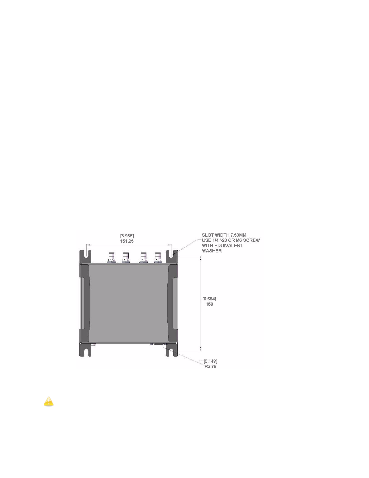
Appendix C: Speedway xPortal Installation .......................................................... 49
RF Beam Pattern ................................................................................................... 49
Mounting the xPortal .............................................................................................. 49
Conduit Attachment ................................................................................................ 51
iv Copyright © 2011, Impinj, Inc.
Page 6

Speedway Revolution Installation and Operations Guide Octane 4.8
Chapter 1: Introduction
Chapter 1: Introduction
About this Guide
This guide provides detailed instructions for installing, connecting, configuring, operating,
upgrading, and troubleshooting the Speedway Revolution or xPortal reader. To shorten the
length of this guide, the content focuses on the installation and operation of one reader.
Intended Audience
The intended audience for this guide is anyone installing a Speedway Revolution or xPortal
reader. The assumed primary users of this guide are systems engineers and IT personnel
with experience and basic knowledge of:
• Software development
• Hardware systems integration
• Network connectivity
This guide also assumes that the user has a high-level understanding of RFID, RFID systems
management, and a basic familiarity with the EPCglobal Gen 2 specification .
Other Documents of Interest
This guide is part of a larger documentation set that supports Speedway Revolution.
The document set includes the following seven documents:
• Speedway Revolution Getting Started Guide is a one-page guide included with
the Speedway Revolution Reader. It provides basic information about the hardware
and instructions for obtaining additional documentation, firmware upgrades and
downloads, and other support software.
• Impinj LTK Programmer’s Guide provides software engineers with guidelines and
best practices for working with the Low Level Reader Protocol (LLRP) Toolkit.
Software engineers can also access language-specific reference guides and sample
applications illustrating the scenarios discussed in the Programmer’s Guide.
• Octane LLRP is intended for software engineers and describes the LLRP capabilities
supported by Speedway Revolution, which includes Impinj’s custom LLRP extensions.
Note: Octane is the name for the Speedway Revolution firmware.
• RShell Reference Manual describes the syntax and command language for the
Speedway Revolution RShell Console.
• Octane SNMP Guide provides monitoring and reference information for working
with the SNMP MIBs related to Speedway Revolution (the standard TCP/IP
networking MIB (MIB-II) and a subset of the standard EPCglobal RM MIB).
• Firmware Upgrade Reference Manual includes detailed procedures, reference
information for upgrading firmware installed on single readers, and procedures for
creating a metafile to automate upgrading of multiple readers.
• Speedway Revolution Embedded Developer’s Guide provides a high-level
description of the Speedway Revolution platform and a high-level view of its
architecture for software engineers designing custom application software for the
reader.
Copyright © 2011, Impinj, Inc. 1
Page 7

Speedway Revolution Installation and Operations Guide Octane 4.8
Chapter 1: Introduction
Impinj Support Information
Visit the Impinj Support Web site at support.impinj.com for information about technical
assistance. For guidelines on capturing data for analysis by Impinj technical support
personnel, seeon page 31.
2 Copyright © 2011, Impinj, Inc.
Page 8

Speedway Revolution Installation and Operations Guide Octane 4.8
Chapter 1: Introduction
Introduction to Speedway® Revolution
Speedway
form factor, UHF Gen2 RFID tag reader. It
provides network connectivity between tag data
and enterprise system software. Speedway
Revolution is built with the same industry-leading
quality, high performance, and excellent
reliability of Impinj’s original Speedway Reader.
Speedway Revolution offers many new features
that increase applicat ion flexibility:
Figure 1.0 Speedway Revolution Reader
• Low Power Usage
With a low power design, Speedway Revolution is capable of using Power over
Ethernet (PoE). Using PoE sim p lifies deployment and dramatically reduces costs and
greenhouse gas emissions of your RFID infrastructure. Using PoE does not
compromise Speedway Revolution performance. It d elivers the full 30 dBm transmit
power
® Revolution is a stationary, small
Note: Using an AC/DC power module, the maximum transmit power is +32.5
dBm. Speedway Revolution supports the IEEE standard 802.3af for PoE.
• Compact Form Factor
The compact size of Speedway Revolution, 7.4 x 6.9 x 1.2 inches or
18.8 x 17.5 x 3 cm, eases installation in tight spaces and embedded applications.
• Two Models Available
Impinj offers two Speedway Revolution models, with different high performance
monostatic antenna port configurations. The transmitter and receiver use the same
port. The model R220 is a two-p ort configu ration and the R420, shown above, is a
four-port configuration.
• High Performance Features
Speedway Revolution uses a variety of high performance features making it possible
to read more than 1100 tags per second. Features include Autoset, Low Duty Cycle,
dynamic antenna switching, inventory search modes that improve tag population
management, and receive sensitivity filtering for read-zone confinement.
• Ease of Use Features
Speedway Revolution uses industry-standard application interfaces; this simplifies
integration with RFID middleware or custom software solutions. It also offers
enterprise-class management and monitoring capability.
Copyright © 2011, Impinj, Inc. 3
Page 9
Speedway Revolution Installation and Operations Guide Octane 4.8
Chapter 1: Introduction
• Robust Reader Design
Just like its Speedway predecessor, Speedway Revolution uses a single circuit board
design that delivers field-proven, enterprise-class quality and reliability.
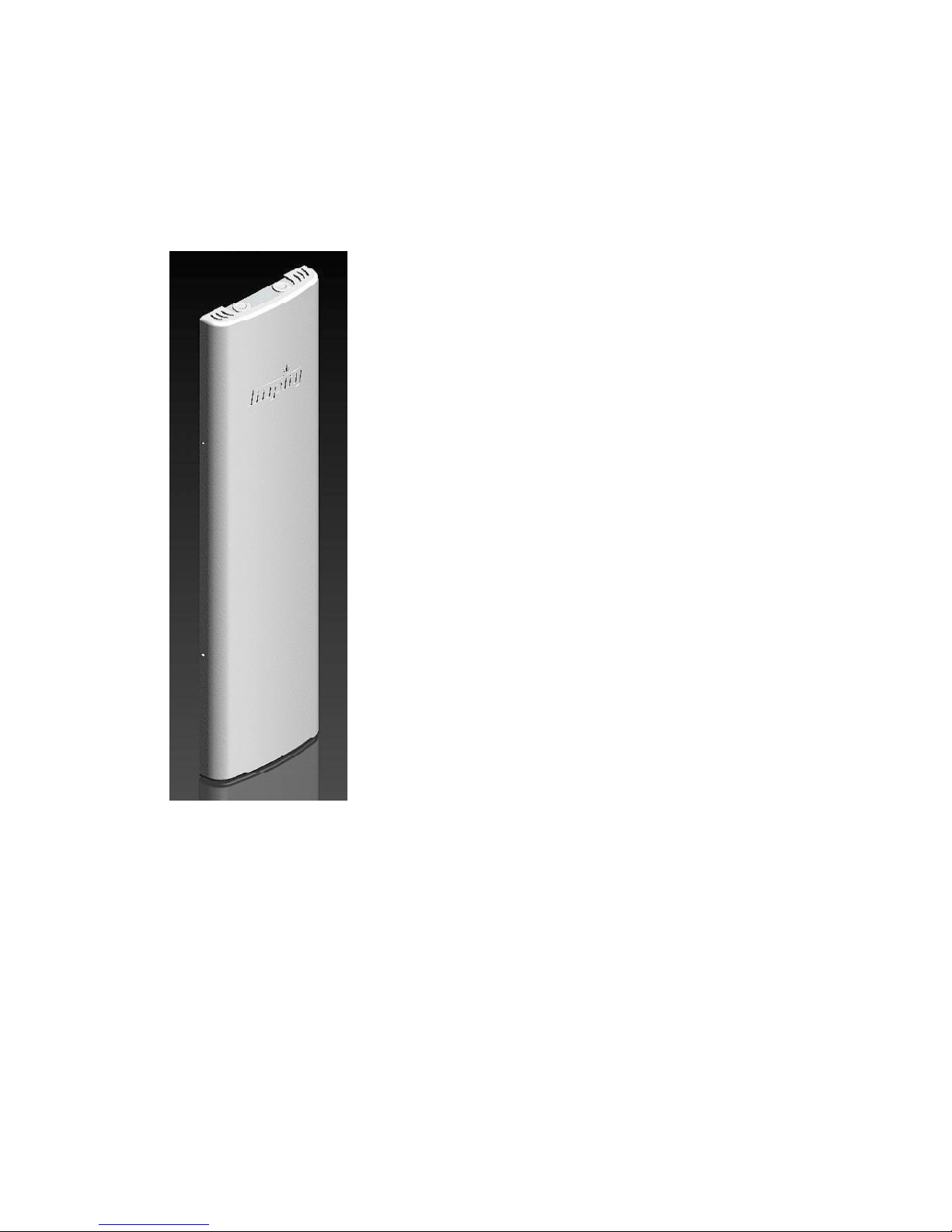
Speedway xPortal – Integrated Portal Reader
The configuring and using the xPortal is identical to the
The newest member of the Speedway family is xPortal an
integrated portal reader. xPortal incorporates the Speedway
Revolution Reader with innovative Dual-Linear Phased Array
(DLPA) antenna technology in a compact, easy-to-install
package. The Speedway xPortal delivers superior
performance and unmatched installation versatility for RFID
read points at doorways, hallways and general zone
coverage in retail, office, hospitality, and healthcare
environments.
Speedway R220 or R420 readers. The following sections also
apply to the xPortal. Appendix C provides the unique
installation and cable hookup instruct ions for the xPortal on
page 49.
The xPortal is an integrated solution with the maximum
reader-transmit power set at the factory to comply with
country of operation regulations. For use in the USA or
Canada under FCC rules, this is 28.5 dBm with xPortal’s
7.5dBi antenna gain.
Figure 1.2 Speedway xPortal-Reader
Requirements for Using Speedway Revolution
Environmental Requirement
• Operating temperature: -20º C to +50º C (non-condensing).
Hardware Requirements
• TCP/IP network equipment is required to connect the reader to a PC (Windows, Mac,
or Linux), or other network terminal.
• Connecting to the reader console port requires a Cisco type management cable (RJ45 to DB9) and either a RS-232 serial port or serial to USB adapter on the PC.
4 Copyright © 2011, Impinj, Inc.
Page 10

Speedway Revolution Installation and Operations Guide Octane 4.8
Ethernet
Telnet-Port 23
Putty 1
SSH or Telnet
Serial
RS-232
higher supports serial)
Minicom
Chapter 1: Introduction
• Impinj-approved UHF RFID antenna or antennas, including associated RF cable or
cables with RP-TNC male connector interface.
Power Requirements
There are two options for powering your Speedway Revolution Reader:
1. Power-Over-Ethernet (PoE)
2. An external universal AC to DC power supply.
PoE offers the most efficient power consumption and supports up to +30 dBm. An external
universal power supply supports up to +32.5 dBm. Operating above +30 dBm requires
professional installation. See Appendix A: Information Specific to Regions of Operation
page 33 for details.
If you are using a universal power supply module, you must use the Impinj approved part,
number IPJ-A2001-000, which supplies +24V + 5%. Available AC power cords are:
• IPJ-A2051-USA (for North America)
• IPJ-A2051-EU1 (for European Union)
• IPJ-A2051-AUS (for Australia, New Zealand)
• IPJ-A2051-BRA (for Brazil)
• IPJ-A2051-CHN (for China)
• IPJ-A2051-JPN (for Japan)
• IPJ-A2051-RSA (for South Africa)
• IPJ-A2051-UK1 (for UK, Singapore, Malaysia, Hong Kong)
Ordering the universal power supply and power cords from Impinj is simple and efficient.
on
Supported Operating Environments
This section describes the environments in which you can access the Speedway Revolution
RShell console used for configuring, monitoring, and maintaining the reader. The tools you
use when accessing the RShell console depend on how you connect your PC to the reader:
serial connection ( RS-232) or Ethernet connection (SSH/Telnet). On PCs running Microsoft
Windows, you can now use Putty for both types of connections.
Table 1.1: Supported Operating Environments
Recommended Tools
Interface Protocol
Microsoft Windows Linux
SSH-Port 22
Putty (version 0.60 and
1. http://www.chiark.greenend.org.uk/~sgtatham/putty/
Supported Communication Protocol
For client control of the reader, Speedway Revolution supports the EPCglobal Low Level
Reader Protocol (LLRP) v1.0.1. LLRP is an EPCglobal standard interface allowing
communication with the reader, which in turn reads EPCglobal Gen 2 RFID tags.
Copyright © 2011, Impinj, Inc. 5
Page 11

Speedway Revolution Installation and Operations Guide Octane 4.8
Chapter 1: Introduction
Antenna Requirements
Depending on the reader model you are installing, Speedway Revolution is equipped with
two (R220) or four (R420) independent, bidirectional, and full duplex TX/RX monostatic
antenna ports.
Antenna requirements vary by regulatory region. For details about the requirements in a
specific region, see the relevant antenna section in Appendix A: Information Specific to
Regions of Operation on page 33.
6 Copyright © 2011, Impinj, Inc.
Page 12

Speedway Revolution Installation and Operations Guide Octane 4 .8
USB (Full
Speed) Device
Console
(RS-232)
Speed) Host
+24Vdc locking
Four RP-TCN RF antenna connectors (R420)
Reader
Antenna 4 and
Antenna 3 and
Antenna 2 and
Antenna 1 and
Power status
Chapter 2: Installing and Connecting
Chapter 2: Installing and Connecting Speedway
Revolution
This chapter provides details about the Speedway Revolution I/O ports and status LEDs, and
explains how to install the reader and connect it to your network.
Speedway Revolution Ports and LEDs
The following graphic illustrates the I/O ports located on the Speedway Revolution Reader.
This graphic illustrates a Speedway R420, which includes four antenna ports visible in Figure
2.2.
Note: Both Speedway R420 and R220 models have the same exterior ports with one
exception; the R220 includes two antenna ports and the Speedway R420 includes four
antenna ports.
Default Restore
button
connector powered
via external power
10/100 base-T Ethernet
(Power over Ethernet)
USB (Full
Figure 2.1 Speedway Revolution R420 Port Connections
RJ-45 connector
GPIO DE-15
4 inputs, 4 outputs
with serial RS-232
Note: See Appendix B: GPIO Details for functional and electrical specifications and
details for each pin of the GPIO DE-15 connectors on page 47.
Antenna ports and LED status indicators are located on the back panel of the reader. The
Speedway R420 graphic below illustrates their locations:
Figure 2.2 Speedway Revolution R420 Antenna Ports and Status LEDs
Copyright © 2011, Impinj, Inc. 7
its status LED
(R220 has two antenna connectors)
its status LED
its status LED
Status LED
its status LED
LED
Page 13

Speedway Revolution Installation and Operations Guide Octane 4 .8
Power
Solid red
Status
Off
Power
Solid green
Status
Off
Power
Solid green
Status
Solid green
Status
Off
seconds
occur
(if present).
Status
Off
antenna port
Antenna
Off
antenna port
Antenna
Solid green
Active LLRP connection
Status
Double blink pattern (green)
Disconnected operation
Status
Single blink pattern (green)
Chapter 2: Installing and Connecting
The following table describes the LED behavior for various reader states:
Table 2.1: Reader Operations and Associated LED Behavior
Reader Operation LED Expected Behavior
Power applied,
attempting to start boot
code
Startup (power on),
normal completion
Startup (reset),
normal completion
Startup (failure)
Upgrade activity
Detection of
antenna activity
Bootloader calling firmware image
Bootloader completed
successfully, reader is
ready
Default Restore
button pressed
Default Restore button
pressed for 3
Default Restore button
pressed for 10 seconds
Hardware problems
detected, unable to boot
Upgrading the firmware
during boot process
Detects no activity on
Detects antenna
transmission activity on
Power Turns off
Power
Power
Power Continuous blinking red
Status
Blinks once (red), indicates a
configuration default restore will
Blinks twice (red), indicates a
factory default restore will
occur. Resets reader
configuration and removes CAP
Alternates between red and
green
Inventory a ctivity
LLRP activity
LLRP activity
Installing and Connecting the Reader
The primary installation and connection steps for Speedway Revolution are:
1. Position the reader appropriately for your environment. This may or may not involve
mounting the reader.
2. Connect the antenna(s) to the appropriate ports on the reader.
8 Copyright © 2011, Impinj, Inc.
Performing an inventory
operation
Status
Blinks orange, blinks faster as
tag volume increases
Page 14
Speedway Revolution Installation and Operations Guide Octane 4 .8
Chapter 2: Installing and Connecting
3. Connect power to the reader.
4. Connect the reader to the network.
5. Configure region setting on the reader (not required if FCC or ETSI).
6. Test the reader installation by reading tags.
Detailed Installation Procedures
This section provides the details for each installation and connection step.
Step 1: Position the Speedway Revolution Reader and ( optionally) Mount the
Reader
Choose the appropriate location for the reader. Ideally you should always keep the unit
away from direct sunlight, high humidity, extreme temperatures, and sources of
electromagnetic interference. Any combination of these conditions may degrade
performance or shorten the life of the unit. Additionally, you need to account for the bend
radius of the coaxial cable at the antenna connection points – if mounting close to another
perpendicular object. The Speedway Reader supports Power over Ethernet (PoE) and can
obtain its electrical power with data via standard cable in an Ethernet network.
If you plan to power the reading using an external universal power supply, confirm there is
a standard 120 or 220 VAC outlet nearby. Depending on your environment, you may need
to mount the reader to a wall or another object.
To mount the Speedway Revolution Reader:
1. Locate the four mounting slots on the reader, as illustrated below:
Figure 2.3 Speedway Revolution Mounting Locations
2. Using ¼ inch diameter bolt with 20 threads per inch (¼–20) or M6 screws, secure
the unit: mount the reader either horizontally or vertically.
Caution: If there is any chance of dust or water exposure, you should mount the reader
so that the Ethernet, USB, Console and GPIO ports are facing down to prevent ingress.
Copyright © 2011, Impinj, Inc. 9
Page 15

Speedway Revolution Installation and Operations Guide Octane 4 .8
Chapter 2: Installing and Connecting
Step 2: Connect the Antenna(s) to the Speedway Revolution Reader
Depending on the Speedway Revolution model you are installing, the reader has either two
antenna ports (R220) or four antenna ports (R420). Each port is independent, bidirectional,
and full duplex TX/RX (monostatic).
Warning: You must use Impinj-approved antennas with Speedway Revolution.
See Appendix A: Information Specific to Regions of Operation on page 33 for a detailed list
of approved vendors. Using any other antenna may adversely affect performance or damage
the reader. Speedway Revolution requires professional installation to correctly set the TX
power for the RF cable and antenna selected.
To connect the antenna(s) to Speedway Revolution:
1. Position each reader antenna, keeping the following points in mind:
• Position the antenna(s) to achieve the most effective and effici e nt tag reads.
• Position the antenna(s) to maximize operator safety. Personnel should remain at
a safe distance at all times. See Appendix A: Information Specific to Regions of
Operation on page 33for the specific requirements for your regulatory region.
2. Mount the antenna(s) according to the instructions provided by the antenna
manufacturer.
3. Attach the antenna cable(s) to the antenna port(s) on the reader. Choose any port
for any antenna.
Finger-tighten each connection, making sure the connection is secure. The antenna
cable is properly tightened when you are no longer able to twist the cable inside the
connector.
Note: A loose connection negatively impacts the performance of the antenna.
Caution: Impinj designed the Speedway Revolut ion antenna ports to be self-
terminating. It is important that you do not terminate unused antenna ports. Leave
them unconnected.
Step 3: Power the Reader
You have two choices for powering Speedway Revolution:
• Power over Ethernet (PoE)
• External universal power supply
If your network switch is PoE-enabled, the reader will power on when you connect it to the
network.
If you are using an external universal power supply, connect the AC power plug into a
suitable 100–240 VAC, 50–60 Hz power outlet.
The boot sequence begins in either case when power is supplied to the reader. This
sequence typically completes within 30 seconds. Once the boot sequence finishes, the
reader accepts commands, not before. The Power and Status LEDs on the reader alert you
the status. See Table 2.1 on page 8 for details.
! Important: If a reader is receiving power via PoE and the reader detects that an external
universal power supply has been connected, the reader reboots and switches to the external
universal power supply source. If, however, the reader is receiving power via an external
universal power supply and detects the connection to a PoE-enabled network switch,
nothing changes. The reader continues to receive power from the external supply. The
10 Copyright © 2011, Impinj, Inc.
Page 16
Speedway Revolution Installation and Operations Guide Octane 4 .8
reader case.
Chapter 2: Installing and Connecting
external universal power supply always takes precedence over PoE because the univers al
power supply is capable of higher power if both sources are connected.
Step 4: Connect Speedway Revolution to the Network
You are now ready to connect the installed Speedway Revolution to your network. You have
two options:
• If your network supports DHCP, you can connect the reader directly to your Ethernet
network. Once the reader is powered, immediately communicate with it via Telnet
(TCP/IP).
• If your network does not support DHCP, you will need to connect a PC directly to the
reader using an RS-232 serial connection. Use the reader’s RShell command line
interface to configure a static IP address for the reader. Once completed, you will be
able to connect the reader to your Ethernet network.
Beginning with Octane 4.8 release WiFi is supported using an adapter connected to the USB
port on SpeedwayR. Only WiFi adpaters using the Realtek 8187 chipset/driver are
supported. Contact Impinj to obtain a list of compatible WiFi USB adapters brands/models
and the RShell Reference Manual for details on how to configure.
Details for completing each connection option are discussed below. Before proceeding, make
note of the reader’s factory default network settings.
Table 2.2: Default Network Settings
Settings Description
Hostname
DHCP Enabled. The reader also reports its hostname to the DHCP server.
SpeedwayR-XX-XX-XX where XX-XX-XX is the last three bytes of the
reader’s MAC address (which is printed on the version label attached to the
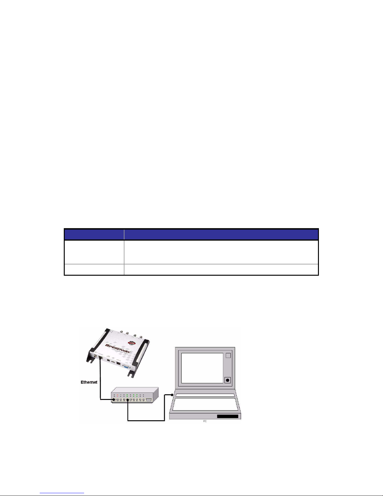
To connect Speedway Revolution to the Ethernet network:
• Using a standard Ethernet cable, connect the RJ-45 connector on the reader to a LAN
drop or network switch. A typical network configuration is illustrated below:
Figure 2.4 Connecting Speedway R e vo lution to the Ethernet Network
Copyright © 2011, Impinj, Inc. 11
Page 17
Speedway Revolution Installation and Operations Guide Octane 4 .8
Chapter 2: Installing and Connecting
Note: If you need to connect a PC directly to the Ethernet port, you can use a standard
Ethernet cable. A crossover cable is not necessary.
Debugging Ethernet network connection:
Steps to try if you encounter difficulty in connecting to the reader over TCP/IP:
1. “ping” the reader, i.e. ping speedwayr-10-28-42.local (for Revolution). If you are on
an enterprise network it is usually not required to use ‘.local’
2. If the ping is NOT successful, it will likely return one of these three error messages:
• “Ping request could not find host”
• “Request timed out”
• “Destination host unreachab le”
The likely cause is that your PC doesn’t have Bonjour Print Services installed. Refer
to http://support.apple.com/kb/dl999
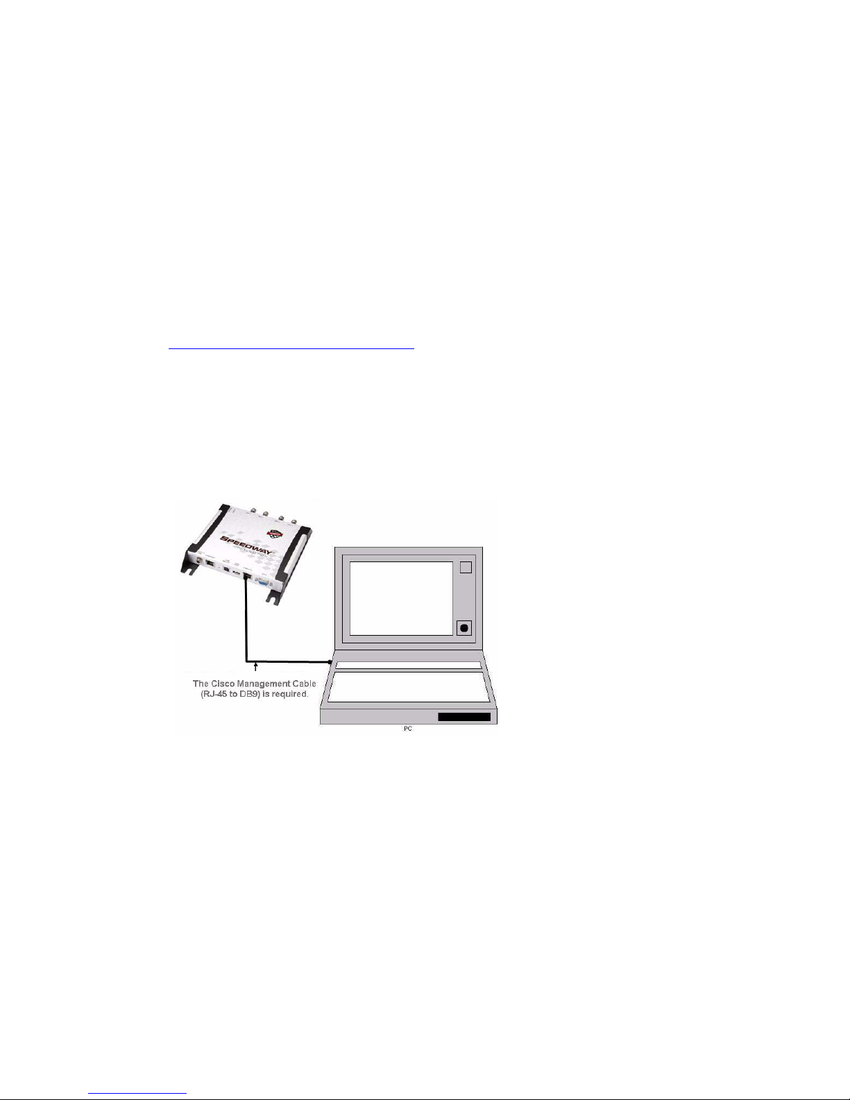
To connect Speedway Revolution to your PC over a serial connection:
1. Confirm you have the latest version of Putty, a free and reliable SSH, Telnet, and
serial client. Version 0.60 or higher contains support for serial connections.
2. Using a Cisco style Console cable RJ-45 to DB9, Impinj part number IPJ-A4000-000,
connect your PC’s valid/active COM port to the serial port on the reader as illustrated
below:
for installation instructions.
Figure 2.5 Speedway Revolution Serial Connection
3. Power up the reader and wait for the boot sequence to complete. (See Step 3: Power
the Reader on page 10.)
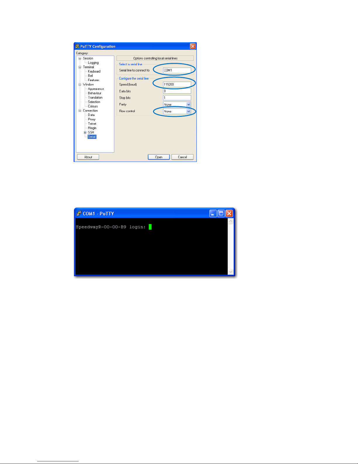
4. On the PC, run the Putty application and select the Serial connection option. Verify
that Serial line to connect to is set to COM1 (may be another COM port if you are
using a serial to USB adapter)
5. Set Speed to 115200.
6. Set Flow control to None.
12 Copyright © 2011, Impinj, Inc.
Page 18
Speedway Revolution Installation and Operations Guide Octane 4 .8
Chapter 2: Installing and Connecting
Figure 2.6 Putty Configuratio n Se ttings
7. Select Open. The RShell console window opens.
8. Press Enter. The RShell login prompt displays.
Figure 2.7 COM1 Putty Login Prompt
9. Log i n with the following default credentials unless you customized them:
user name: root
password: impinj
10. When the RShell command line prompt displays, begin configuring the network
settings for the reader. See Using RShell to Configure Network Settings for
Speedway Revolutionon page 16 for details.
11. When you have completed configuration of the appropriate network settings, connect
the reader to your Ethernet network as described on page 11.
Note: If you decide to connect to DHCP after connecting serially, remember to use
RShell to change the IP address on the reader from static to dynamic. See
to Configure Network Settings for Speedway Revolution on page 16 for details.
Copyright © 2011, Impinj, Inc. 13
Using RShell
Page 19

Speedway Revolution Installation and Operations Guide Octane 4 .8
Chapter 2: Installing and Connecting
Step 5: Configure the Region Setting on the Reader
GX1 or GX2 reader models that support multiple countries required that the professional
installer set the specific region of operation. Note FCC or ETSI readers cannot be altered
and only operate per the regulatory laws in USA/Canada, or European Union.
Warning: The RF settings must match the country/region of operating to comply with
local laws and regulations. You, the user, are responsible to ensure operation with the
correct RF settings and are solely responsible for any fines and other damages due to
incorrect or non-compliant country/region settings on your reader.
Out of the box, GX1 and GX2 readers have no region configured (null region) and will not
transmit RFID signals. The region can be selected and set using the reader’s http interface
(web browser) or using RShell. The procedure to set region via web interface is as follows:
1. Connect to the reader using a web browser http://<reader name or IP address>.
Examples: http://speedwayr-10-00-DD or http://10.0.10.44.
2. Log in to the reader;
user name: root
password: impinj
3. Select one of the available regions from the drop down list, see figure 2.8
Note: if you do not see your country or region listed, contact Impinj regarding
current regulatory approval status.
4. Click the REBOOT button. When changing the reader's operating region, the effect
of the change does not take effect until the next reboot. Attempting RFID operations
on the reader after changing the region but before rebooti ng will result in undefin e d
behavior.
Alternately, the following RShell commands will set or change a GX1 or GX2 region of
operation:
show system region – shows the configured region and list of selectable regions.
config system region X – set the region to region number X, example config
system region 15, sets region on GX1 to Singapore.
Figure 2.8 Change Regulatory Region Web Interface
14 Copyright © 2011, Impinj, Inc.
Page 20

Speedway Revolution Installation and Operations Guide Octane 4 .8
Chapter 2: Installing and Connecting
Step 6: Test the Installed Reader
Confirm connections and functionality is correct by reading tags. Using the MultiReader, a
Windows PC test application from Impinj, you can quickly verify reader operation by
configuring various reader parameters and running simple inventory operations. For details
about how to access and use MultiReader, see page 17
Copyright © 2011, Impinj, Inc. 15
Page 21

Speedway Revolution Installation and Operations Guide Octane 4.8
Chapter 3: Configuring and Monitori ng
Chapter 3: Configuring and Monit or i ng
Speedway Revolution
This chapter provides a high-level view of the configuration and monitoring options available
for Speedway Revolution.
Configuring Speedway Revolution
You can think of Speedway Revolution configuration in two categories: configuring the
device itself and configuring the reader’s RF behavior. This chapter provides the basics for
each type of configuration.
Device Configuration
RShell is a proprietary command line management interface for configuring and managing
network settings, firmware upgrades, and other device-oriented operations. This chapter
introduces the RShell commands for installing and connecting the reader. RShell Reference
Manual provides full details and syntax for all RShell commands.
Note: RShell is a machine interface and is almost always backward-compatible with
previous Speedway Revolution versions. Existing inputs and outputs will never change.
When adding new commands, new optional arguments will be added at the end.
! Important: The Speedway Revolution version of RShell is not 100% compatible with the
original Speedway reader.
Using RShell to Configure Network Settings for Speedway Revolution
You can often get up and running with little or no configuration using the default
configuration settings in Speedway Revolution. If you are not using DHCP to assign IP
addresses, you will need to configure a few of the reader’s network settings.
The following procedure outlines the RShell commands you may need for connecting the
reader to your network.
To configure the reader’s network settings:
1. Open the RShell console (see page 12 for details).
2. View the reader’s current configuration settings by entering the show network
summary command at the RShell command prompt:
> show network summary
Status='0,Success'
PrimaryInterface='eth0'
ActiveInterface='eth0'
Hostname='SpeedwayR-00-00-B9'
connectionStatus='Connected'
ipAddressMode='Dynamic'
ipAddress='10.0.10.41'
ipMask='255.255.0.0'
gatewayAddress='10.0.0.10'
broadcastAddress='10.0.255.255'
LLAStatus='enabled'
16 Copyright © 2011, Impinj, Inc.
Page 22

Speedway Revolution Installation and Operations Guide Octane 4 .8
Chapter 3: Configuring and Monitoring
3. Configu re the appropriate TCP / IP parameters for your environment. The applicable
commands are:
• Setting Hostname
> config network hostname <HOSTNAME>
• Setting Static IP Address
> config network ip static <IP ADDRESS> <NETMASK> <GATEWAY>
Note: The IP address is required; the other parameters are optional. The default value
is used if an optional parameter is omitted from the ip command.
• Enabling DHCP
> config network ip dynamic
• Configuring NTP Servers
> config network ntp add <NTP SERVER ADDRESS>
4. After successfully configuring all required network settings, connect the reader to the
network via the Speedway Revolution Ethernet port.
RF Configuration
Configuring your reader’s RF behavior depends entirely on your implementation approach.
You may be using a custom software application, middleware running on a server, or some
other approach. MultiReader (see below) is an example of a PC client application.
Regardless of the application you’re using, the underlying protocol is the same—Low-Level
Reader Protocol (LLRP).
LLRP is a standard, asymmetric, binary protocol used for communication between a client
application and the reader. LLRP controls the configuration of the antenna transmit power,
the receive sensitivity, the operating reader, and more. For details about LLRP, see one or
more of the following documents:
• LLRP Standard: This document provides the specifics of the EPCglobal-ratified LLRP
standard. http://www.epcglobalinc.org/standards/llrp/llrp_1_0_1-standard-
20070813.pdf
• Octane LLRP: Provides details of the LLRP capabilities supported by Speedway
Revolution. It also describes custom LLRP extensions added by Impinj.
• Impinj LTK Programmer’s Guide: Is intended for software engineers and provides
guidelines and best practices for working with the LLRP Toolkit. In addition, software
engineers can access language-specific reference guides and sample applications
illustrating the scenarios discussed in the Programmer’s Guide.
Using MultiReader to Configure and Test Speedway Revolution
Impinj provides a simple, easy-to-use LLRP application for configuring and testing the basic
RF behavior of Speedway Revolution. The MultiReader application is available from the
Impinj support Web site at support.impinj.com. MultiReader version 6.6.X supports features
available with Octane 4.8.X firmware. To use MultiReader, your computer must be running
Microsoft Windows XP.
Note: MultiReader will in stall and operate on Windows7, but is not fully tested a nd
supported. We recommend MultiReader for test purposes only. MultiReader is now available
from “downloads” at
support.impinj.com.
Copyright © 2011, Impinj, Inc. 17
Page 23

Speedway Revolution Installation and Operations Guide Octane 4.8
Chapter 3: Configuring and Monitori ng
This section covers connecting to and configuring a reader’s RF parameters using
MultiReader. It also provides a high-level description of each parameter.
To configure and test a reader from within MultiReader:
1. Install and launch the MultiReader application. The following screen displays:
Figure 3.1 MultiReader initial screen
2. Select Configure Settings. The Reader Settings screen displays:
Figure 3.2 Multireader Reader Settings Connection Screen
3. Connect to the reader by typing the reader’s IP address or hostname in the Name or
IP Address field.
You can determine the name and the IP address via the RShell show network
summary command.
18 Copyright © 2011, Impinj, Inc.
Page 24

Speedway Revolution Installation and Operations Guide Octane 4 .8
Chapter 3: Configuring and Monitoring
Note: The show network summary command provides the dynamic valu e s returned by
DHCP or LLA if the current configuration is dynamic. The local hostname resolution feature
(mDNS) gives the reader a local hostname in addition to an IP address as its network
identity. On an isolate d network that lacks DNS service but has mDNS enabled, a reader
with hostname speedwayr-00-01-02, for example, may be reached using
speedwayr-00-01-02.local.
4. In Model, select t he appropriate Speedway Revolution model (either Speedway R220
or Speedway R420). If you want MultiReader to issue a warning if it detects a model
other than what is configured, confirm Warn on the model mismatch checkbox is
selected. (Model mismatch is selected by default.)
5. Configure the key RF parameters described below:
6. Under Reader 1, on the left side of the Reader Settings dialog box, select Modes, RF,
and Power. The following scree n displays:
Figure 3.3 Multireader Reader Settings Settings Scr een
7. In Reader Mode, select AutoSet Dense Reader. The Reader Mode specifies the
rules to use for communication between the reader and tag. With AutoSet Dense
enabled, the reader automatically senses the environment and adjusts its mode
accordingly.
8. In Search Mode, select Dual Target. In Session, select Session 1. Search Mode
and Session work together to control when and how often the reader reads a tag.
The high-level functional description for the reader is: Each tag contains a flag that is
flipped from A to B or from B to A when it is read. The Session value controls how
long the flag retains its value before reverting back to the original tag value. Search
Mode controls which flag values the reader reads and, in some cases, what happens
to the flag value once the tag is read.
With Dual Target, the reader reads all the tags with A flags, after reading the tags
the reader flips each tag to B. When there are no more A tags to read, the reader
reads all the B tags, flipping each one to A after it has been read. It continues this
process back and forth from A to B and back to A. Session 1 ensures a persistence
period that prevents tags from reverting before they have all been read.
Copyright © 2011, Impinj, Inc. 19
Page 25

Speedway Revolution Installation and Operations Guide Octane 4.8
Chapter 3: Configuring and Monitori ng
9. On the right of the screen is a checkbox for each of the reader’s antenna ports. By
default, all antennas are enabled. Deselect the checkbox for any port without a
connected antenna. Leaving all ports enabled does no harm, but does waste
processing time because the reader reads all enabled ports. The reader verifies the
presence of an antenna before attempting to activate it.
10. Set the appropriate transmit power, Tx Power, and receive sensitivity, Rx
Sensitivity, for each enabled antenna.
Transmit power controls the power of the signal leaving the antenna and the signal
range. The optimal setting depends on many things:
• how you are powering the reader
• cable length connecting the antenna to the reader
• number of antennas in the area
• anticipated distance between the antenna and the tags
Use the default value of 30 dBm for testing purposes.
Receive sensitivity c ontrols the tag signal th r e shold below which the tag is ignored by
the reader. This parameter is useful in mitigating stray reads. Stray tags often have
a weaker signal than the tags to be read. The Max checkbox is selected by default,
and tells the reader to read all tags, regardless of the tag’s signal strength. This is
known as its Received Signal Strength Indicator—or RSSI.
When configuring a specific receive sensitivity, deselect the Max checkbox, and then
type the value you want for each connected antenna. The maximum sensitivity is -
80.
Remember, you are simply configuring the reader to test your installation. Adjust
these settings later when you begin using the reader in a live RFID operation if
desired.
11. Select Apply. MultiReader displays a progress bar as it connects to the reader. When
the connection completes, the following status displays at the bottom of the
application:
Figure 3.4 Multireader Status Display
12. Test your reader installation. Place one or more tags in the read-zone of one or more
of the attached antennas. Select START Inventory. Tag reads appear in the large
gray area on the left:
Figure 3.5 Multireader Tag Inventory Display
20 Copyright © 2011, Impinj, Inc.
Page 26

Speedway Revolution Installation and Operations Guide Octane 4 .8
dhcp
Summary of DHCP client configurati on
dhcp
Summary of DNS settings
icmp
ICMP statistics
ip
IP statistics
ntp
Summary of NTP settings
summary
Summary of network settings
Chapter 3: Configuring and Monitoring
In this case, the reader detected five tags. Because the search mode is Dual Target,
the reader continuously reads the tags, first reading the A flags, and then reading
the B flags. Notice in the above image that one of the tag entries is a pinkish color.
The tag entry changes to red when a tag is not actively read. For example, if you
change the Search Mode to Single Target with Suppression, the reader reads
each tag only once. All five entries would quickly turn red and stay red as shown
below.
Figure 3.6 Multireader Tag Inventory Aging Display
If you see tag data appearing in MultiReader, your reader is most likely installed
correctly and the antennas are functioning properly. If you don’t see all the tags you
placed in the read-zone, try moving the tags to a slightly different location or
orientation.
13. Select STOP Inventory Run to stop the tag inventory process.
Monitoring Speedway Revolution
Use RShell to monitor the reader health and performance when Speedway Revolution is up
and running. This section presents the primary RShell commands for viewing the network
and RFID statistics, plus the reader logs. For details about these commands, see the RShell
Reference Manual.
Speedway Revolution also supports industry standard SNMP, with MIB2 and EPCglobal
Reader Management MIB. For more information, see the Octane SNMP Guide.
Viewing Network Parameters and Statistics
Use the RShell show network command to display networking parameters and
statistics. Using this command with the indicated parameters, you can view the
following information:
Table 3.1: Show network Command Parameters
Parameter
Displayed Information
Copyright © 2011, Impinj, Inc. 21
Page 27

Speedway Revolution Installation and Operations Guide Octane 4.8
tcp
TCP statistics
udp
UDP statistics
Parameter
Displayed Information
ReaderOperationalStatus
running on the reader
Antenna<n>OperationalStatus
4).
Antenna<n>EnergizedTime
powered, in milliseconds.
Antenna<n>UniqueInventory-Count
antenna<n>
Antenna<n>TotalInventory-Count
antenna<n>
Antenna<n>ReadCount
antenna<n> that matched the configured filters.
Antenna<n>FailedReadCount
failed.
Chapter 3: Configuring and Monitori ng
Parameter
Displayed Information
For details about the specific settings and statistics available for each of these parameters,
see the RShell Reference Manual.
Viewing RFID Parameters and Statistics
Use the RShell show rfid stat command to display a reader’s RFID parameters and
statistics. Using this command with the appropriate parameter, you can view information
shown in the Parameter and display table below.
Table 3.2: Partial listing of show rfid stat parameters
Indicates whether RFID applic ations are
Indicates if an antenna is physically connected
to the reader and operating properly. Note that
<n> indicates the antenna port on the reader (1-
Indicates the time that antenna<n> has been
Indicates the number of unique tags seen at
Indicates the total inventory count for
Indicates the number of tags read at
Indicates the number of tags where a r ead was
attempted at antenna<n> because the tag
matched the configured filter, but the read
Table 3.2 shows a sample of t he available RFID statistics. For the full list as well as syntax
details, see the RShell Referenc e Manual.
Note: View Statistics on the LLRP interfac e between the reader and a client by entering
the show rfid llrp stat command. The RShell Reference Manual provides details.
Configuring and Viewing Speedway Revolution Logs
Speedway Revolution uses the standard Syslog protocol to forward its logged events to a
remote Syslog server. The reader stores the logged event s in its file system, accumulatin g
and retaining this information across reboots. Logs are classified into three cat egories:
Management, RFID, and System.
All logged events have an associated severity level. There are eight possib le levels listed in
decreasing order from most severe to least severe:
1. Emergency
2. Alert
22 Copyright © 2011, Impinj, Inc.
Page 28

Speedway Revolution Installation and Operations Guide Octane 4 .8
Chapter 3: Configuring and Monitoring
3. Critical
4. Error
5. Warning
6. Notice
7. Info
8. Debug
Configure the log levels you want to display. The reader then retains only the events with a
severity greater than or equal to the configured level. For example, if you choose a logging
level of Warning, then the logs will contain the follo wing levels: Warning , Error, Critical,
Alert, and Emergency.
Note: Regardless of the configured log level, the reader always retains logs of Error level
or higher in an independent log.
Use the RShell config logging command to configure options for the storage and forwarding
of logged events. Use the show logging command to display the logging configuration as
well as the actual logged information in text form. For details about these commands, see
the RShell Reference Manual.
Viewing the State of the Speedway Revolution Device
To display information about the current state of the reader itself, use the RShell show
system command. Using this command allows viewing the following statistics:
• A summary of system information—show system summary
• Platform memory usage and available application space—show system cpu
• Generic platform statistics—show system platform
For more details about the show system command, see the RShell Reference Manu a l.
Copyright © 2011, Impinj, Inc. 23
Page 29

Speedway Revolution Installation and Operations Guide Octane 4 .8
Chapter 4: Upgrading Firmware
Chapter 4: Upgrading the Speed w a y Rev ol ut i o n
Firmware
Speedway Revolution contains firmware known as Octane. The current version of Octane is
4.8. This chapter details manually upgrading a single reader.
In addition to supporting upgrade procedures, Speedway Revolution also provides methods
for reverting firmware to a previous valid image and restoring firmware to factory default
settings. The procedure for reverting to the previous valid image is explained in this
chapter, while returning to factory defaults is explained in Chapter 5 on page 29.
A Brief Overview of the Speedway Revolution Firmware
To minimize downtime and maximize the robust handling of possible upgrade failures,
Speedway Revolution contains dual images of its firmware. When requesting a firmware
image upgrade, the reader continues to operate using the primary image. In the
background, Speedway Revolution upgrades the secondary image. When the upgrade
completes, the reader reboots to the newly upgraded image. Sp eed way Revolution retains
the previous firmware version in case there are problems with the upgrade.
There are three individual partitions within each firmware image that logically organize the
system software. Although you do not need a full understanding of this architecture to
perform a simple manual upgrade, it is a good idea to be familiar with its structure at a high
level. For a more in-depth discussion of the firm wa r e and ho w firmware is organized, see
the Embedded Developer’s Guide.
The three partitions in firmware are:
1. System Operating Partition (SOP)—The SOP is the primary system partition of
the Speedway Revolution reader. It contains the Linux kernel, FPGA firmware, RFID
management software, reader management software (RShell), logging management
software, firmware upgrade control, system watchdog software, and the factory
default data.
2. System Persistent Partition (SPP)—Files in this partition are automatically
generated and maintained by the software running on the reader. It contains the
reader configuration (network settings, LLRP configuration, log settings, and so on),
reader logs, and debug information used by Impinj engineers.
3. Custom Application Partition (CAP)—CAP partition contains custom application
software, other items required by the custom application (extra libraries or tools, and
configuration files ), plus custom application logs.
Upgrading the Firmware
Speedway Revolution provides three methods for upgrading:
1. Using RShell, command line interface.
2. Copying the firmware to a USB memory drive and plugging into the reader’s host
port.
3. Via the web interface.
24 Copyright © 2011, Impinj, Inc.
Page 30

Speedway Revolution Installation and Operations Guide Octane 4 .8
Chapter 4: Upgrading Firmware
Upgrading the Firmware using RShell:
1. Obtain t he firmware upgrade file from the Impinj support Web site,
support.impinj.com. The upgrade file extension is .upg. (Example:
octane_4_8_0.upg).
2. Place the upgrade file on a serv er (http , tftp, or ftp) accessible by the reader you are
upgrading.
3. Using the Putty application, connect the reader using telnet, SSH or serial and log in.
4. From the RShell command prompt, issue the following command:
> config image upgrade <URI>
Where <URI> is the server location and name of the upgrade file.
For example:
> config image upgrade http://usacorp/rfid/reader/image/
octane_4_8_0.upg
> config image upgrade ftp://anonymous:abc@myserver/
ftpdirecotry/octane_4_8_0.upg.upg
> tftp://server/octane_4_8_0.upg
5. After starting the upgrade, view the upgrade status at any time by issuing the
following command:
> show image summary
6. This command prov ides a display of the current upg rad e status, the last operation ,
the status of the last operation, and information about the primary and secondary
images. Reissue the show image summary command if you want to track th e
upgrade status. Some status values you may see are:
WaitingForImageFileTransfer
WaitingForCommitImage
WaitingToActivateImmediate
The upgrade is complete when the UpgradeStatus parameter v alue is
Ready.
The LastOperation parameter should be WaitingToActivateImmediate and the
LastOperationStatus should be WaitingForManualReboot.
7. Reboot the reader by issuing the following command:
> reboot
Speedway Revolution reboot process displays messages in the RShell console as it goes
through each stage of the process. The reboot completes then the reader login prompt
displays on the console. The reader status light displays solid green. LED reader reboot
behavior details are provided on page 8.
Upgrading the Firmware with a USB Drive
Speedway Revolution running Octane 4.4 and later supports upgrading the firmware using a
USB drive.
First, obtain the firmware upgrade file from the Impinj support Web site,
support.impinj.com. The upgrade file extension is .upg. (Example: octane_4_8_0.upg).
Copyright © 2011, Impinj, Inc. 25
Page 31

Speedway Revolution Installation and Operations Guide Octane 4 .8
Chapter 4: Upgrading Firmware
Preparing the USB Drive for upgrade
1. Insert a USB drive into your computer.
2. Create an impinj directory in the root of the USB drive along with the subdirectories
revolution, upgrade, and images. The names of the directory are case sensitive and
must all be lower case.
3. Copy the desired firmware upgrade .upg file into the
\impinj\revolution\upgrade\images\ directory.
Note: If multiple .upg file s exist in the images directory, the reader will use the
most recently modified file.
4. Remove the USB drive from your computer.
Using the USB Drive
1. Confirm that the reader is ready for upgrade with both the Power and Status LEDs
illuminated.
2. Insert the USB drive into the “USB Host” port on the reader. W ithin 5-10 seconds,
the reader will begin upgrading the reader and the Power LED will blink amber. If the
Power LED remains solid green, the reader likely cannot locate the images directory
and .upg file on the USB drive.
3. The upgrade process completes in 20-60 seconds and then the Power LED will
change to solid green.
5. Remove the USB drive from the “USB Host” port and reboot the reader.
During the upgrade process, the reader will attempt to append information to a
“status.log” file in the “impinj/revolution/upgrade” directory. The “status.log” file is
intended to provide an audit trail for the upgrade of one or more readers.
If the firmware upgrade process fails the Power LED will blink red. Remove the USB drive
reboot the reader and check the “status.log” file for the reason of the failure.
Upgrading the Firmware through the Impinj Management Web UI
Speedway Revolution running Octane 4.4 and later supports upgrading the
firmware using the Impinj Management Web UI.
5. Connect to the reader using a web browser http://<reader name or IP address>.
Examples: http://speedwayr-10-00-DD or http://10.0.10.44.
6. Log in to the reader;
user name: root
password: impinj
7. Click the Browse button and then select the firmware upgrade .upg file.
8. Click the Upgrade button.
9. After the upgrade is complete, click the reset button.
26 Copyright © 2011, Impinj, Inc.
Page 32

Speedway Revolution Installation and Operations Guide Octane 4 .8
Chapter 4: Upgrading Firmware
Figure 4.1 Speedway Revolution Management Web Page
Figure 4.2 Close-up of Reader Upgrade and Reboot Section of Management Web
Page
Copyright © 2011, Impinj, Inc. 27
Page 33

Speedway Revolution Installation and Operations Guide Octane 4 .8
Chapter 4: Upgrading Firmware
To fall back to the previous image
1. To revert to the pre-upgrade image, enter the following command from the RShell
prompt:
> config image fallback
When the command completes successfully, the reader automatically reboots and
returns to the login prompt.
2. Log in to the reader. The pre-upgrade image is now running.
Note: If there is no valid previous image, the response to the config image
fallback command is Status=‘8, Permission-Denied’.
28 Copyright © 2011, Impinj, Inc.
Page 34

Speedway Revolution Installation and Operations Guide Octane 4 .8
Default Restore
Chapter 5: Troubleshooting
Chapter 5: Troubleshooting
If you experience a problem with Speedway Revolution, this brief c hapter presents a few
suggestions to correct the issue.
Returning to the Default Configuration
If you are experiencing a problem with the reader and are having difficulty pinpointing the
cause, it is useful to return the reader to a known state. We recommend resetting to the
default configuration. Then try your reader again.
! Important: Configuration Default Restore returns the reader configuration to its default
state. It leaves any custom applications installed in the CAP intact. To restore the reader to
its default state and remove any CAP contents, use Factory Default Restore. See the
Warning on page 30.
There are two ways to return Speedway Revolution to its defaults:
1. Issue an RShell command.
2. Push the Default Restore button on the device.
To use RShell to return the reader to its default configuration and leaving CAP
intact
1. At the RShell prompt, enter the following command:
> config image default
When the command completes successfully, the reader automatical ly reb o ots and
returns to the login prompt.
2. Log in to the reader. The reader is now running with the default configurat ion . CAP
applications are intact.
To use the Default Restore button on the reader to restore to its default
configuration
1. Use an object with a sharp tip, such as a probe or paper clip to press and hold the
Default Restore button on the back of the reader while applying power to the
reader.
2. Continue holding the Default Restore button for 3 seconds after the Power LED light
turns off, but not longer than 10 seconds.
3. Release the Default Restore button when the LED blinks red once. The reader will
boot up normally with the default configura tion.
Figure 5.1 Default Restore button
button
Insert and hold sharp point here for
3 seconds. Release before 10
seconds.
Copyright © 2011, Impinj, Inc. 29
Page 35

Speedway Revolution Installation and Operations Guide Octane 4 .8
root
Password
impinj
Upgrade Retrieve Mode
Manual
Management Logging Level
Error
RFID Logging Level
Error
Error
Dynamic (DHCP)
DHCP Send Hostname
On
address)
Static DNS Servers
None
LLRP Inbound Port
5084
LLRP Inbound Service
Enabled
LLRP Outbound Retry Secs
5
2
Chapter 5: Troubleshooting
Warning: Pressing the Default Restore button for 10 seconds or more will cause a
factory default restore to occur. The factory default restore removes the reader’s custom
application partition (CAP) if one exists. The reader returns to the original, factory shipped
state. It is important to avoid accidentally removing the CAP. There may be situations where
CAP removal is necessary.
The following table lists the default configuration values:
Table 5.1: Default Configuration Values
Parameter Default Value
User
Logging No syslog servers
System Logging Level
Network Mode
speedwayr-xx-xx-xx
Hostname
Static NTP Servers None
LLRP Outbound Service Enabled
LLRP Outbound Servers None
LLRP Outbound Timeout Secs
(where xx-xx-xx are the last three digits of the M AC
30 Copyright © 2011, Impinj, Inc.
Page 36

Speedway Revolution Installation and Operations Guide Octane 4 .8
Chapter 5: Troubleshooting
Submitting Diagnostic Data for Analysis by Impinj Technical
Support
If Speedway Revolution is exhibiting RF behavior differing from what you expect and you
are unable to determine the cause, you may want to submit relevant data for analysis by
Impinj Technical Support. Using the Impinj MultiReader application, you can easily capture
data relating to the problem scenario. By creating and providing a Reader Diagnostic Data
file, Impinj’s Techn ical Support team can troubleshoot your issue.
To capture data to a Reader Diagnostic Data file:
1. Open MultiReader and connect to the appropriate Speedway Revolution reader. See
page 16 for details.
2. Select Configure Settings to open the Reader Settings screen.
3. Verify that you are viewing the connection settings for Reader 1. If you are not,
select Reader 1 in the menu on the left.
4. In Control Reader, select No.
This setting value tells MultiReader that you do not want the MultiReader
configuration controlling the reader. Changing this value is important because you
most likely want to capture data for a reader operation that is being controlled by
your application.
If, however, you want to capture an RF scenario that is controlled by MultiReader,
set Control Reader to Yes.
5. In the menu on the left, select Data Capture. The following screen displays:
Figure 5.2 Reader Settings, Tag History & Debug Data Capture
Reader 1 is already populated with the IP address. Login parameters are also populated. If
these values are incorrect, change them here. You can capture data for up to four readers
simultaneously. In this example, we are capturing data one reader.
6. Confirm that Capture is set to On.
7. Select Apply.
MultiReader connects to the reader and begins “listening” for any RF activity. The reader
captures data surrounding any RF activity it detects.
Copyright © 2011, Impinj, Inc. 31
Page 37

Speedway Revolution Installation and Operations Guide Octane 4 .8
Chapter 5: Troubleshooting
8. Perform the RF activity to submit for analysis.
9. Select File in the upper left corn er of the applicat ion .
This completes the capture activity.
10. Select Save Debug Data.... A browse window opens.
11. Enter a file name and save the file in the desired location.
12. Send the .rdd file containing binary data to Impinj Technical Support.
Visit the Impinj support Web site, support.impinj.com., for submission details or talk
with your Impinj representative.
Note: Another option is to create a network trace using Wireshark, a free protocol
analyzer download from the Internet.
32 Copyright © 2011, Impinj, Inc.
Page 38

Speedway Revolution Installation and Operations Guide Octane 4.8
Appendix A: Region Specific Information
Appendix A: Information Speci f i c to Regions of
Operation
Speedway Revolution is designed to work in various regulatory regions. This appendix
contains frequency ranges and antenna requirements specific to each supported region.
Operation in North America
Frequency Plan
The FCC specifies frequency hopping across the North American spectrum allocated to UHF
RFID (902-928 MHz, with hopping occurring between 902.75-927.25 MHz in 500 KHz
steps). The frequency plan is further explained in the table below:
Table A.1: Frequency Plan for North America
Transmit Channel Number Center Frequency (MHz)
1 902.75
2 903.25
3 903.75
4 904.25
… …
49 926.75
50 927.25
Antenna Requirements
Positioning
Position the antenna’s surface at least 25 centimeters away from personnel working in the
area. This is an FCC positioning requirement. For more details, see the following FCC
bulletins:
• FCC OET Bulletin 65: Evaluating Compliance with FCC Guidelines for Human
Exposure to Radiofrequency Electromagnetic Fields
• FCC OET Bulletin 56: Questions and Answers about Biological Effects and Potential
Hazards of Radiofrequency Electromagnetic Fields
Installation
Speedway Revolution is capable of up to +32.5 dBm conducted power on the housing RF
connector and requires professional installation.
Power
Speedway Revolution may only be operated with Impinj-approved antennas and can radiate
no more than 36 dBm EIRP per FCC Part 15.247 regulations. The Speedway Revolution
output power may be increased to provide the maximum allowable EIRP subject to a
Copyright © 2011, Impinj, Inc. 33
Page 39

Speedway Revolution Installation and Operations Guide Octane 4 .8
Appendix A: Region Specific Information
maximum conducted power allowance of 30 dBm at the antenna connect or . The maximum
allowable output power of the reader can be set to satisfy both the conductor and radiated
maximum criteria. The expression for the maximum reader power setting is:
Maximum power setting (in dBm) = the Smaller of :
(36 – Composite Antenna Gain (in dBm)) OR (30 + Cable Loss (in dBm)
where the composite antenna gain comprises the maximum linear antenna gain in dBi
minus any cable loss between the reader and antenna in dB. Approved antenna vendors,
model numbers, and associated gain are listed in the next section.
Note: The composite antenna gain comprises the maximum linear antenna gain in dBi
minus any cable loss between the reader and antenna in dB. Approved antenna vendors,
model numbers, and associated gain are listed in the next section.
Approved Antennas
• Laird Technologies model number S9028PCL/R (left- or right-hand CP), with
integrated 8 foot pigtail to RP-TNC male connector; 6 dBi composite gain
• Impinj model number IPJ-A0301-USA (Mini-Guardrail) with SMA female connector; 15 dBi gain
• Impinj model number IPJ-A0310-USA Threshold Antennas (IPJ-A0311-USA and IPJA0311-EU1) with 12 inch integrated pigtail to BNC male connector, 6 dBi composite
gain.
• Impinj model number IPJ-A0400-USA, CSL CS-777-2 (Brickyard) with 7 foot
integrated pigtail to RP-TNC male connector; 2 dBi composite gain
• Impinj model number IPJ-A0401-USA or IPJ-A0402-USA (both Guardwall) with 6 foot
integrated pigtail to RP-TNC male connector; 6 dBi composite gain
• Impinj model number IPJ-A0404-000, Matchbox antenna with 20cm integrated
pigtall to SMA connector; -20 dBi composite gain.
• MA/COM MAAN-000246-FL1 integrated RFID floor-mounted stand (multiple
configurations available, 2 or 4 antennas left-hand and right-hand CP) with 8 foot
integrated pigtail to RP-TNC male connector; 6 dBi composite gain
• MA/COM MAAN-000246-WL1 integrated RFID wall-mounted stand (multiple
configurations available, 2 antennas left-ha nd a nd ri g ht-hand CP) with 8 foot
integrated pigtail to RP-TNC male connector; 6 dBi composite gain
• MTI MT-262006/TLH (left-hand CP) or MT-262006/TRH (right-hand CP) with RPTNC
female connector (antennas available in IP54 or IP67 ratings); 6 dBi gain
• MTI MT-262013/NLH (left-hand CP) or MT-262013/NRH (right-hand CP) with Ntype
female connector (antennas available in IP54 or IP67 ratings); 4.5 dBi gain
• MTI MT-262013/TLH (left-hand CP) or MT-262013/TRH (right-hand C P) with RPTNC
female connector (antennas available in IP54 or IP67 ratings); 4.5 dBi gain
• Sensormatic Electronics Corp. model number IDANT20TNA25 with 25 foot Belden
7806A RG-58 coaxial cable (0.1 dB per foot loss) to RP-TNC male connector; 5.5 dBi
composite gain
• Sensormatic Electronics Corp. model number IDANT10CNA25 with 25 foot Belden
7806A coaxial cable (0.1 dB per foot loss) to RP-TNC male connector; 3.5 dBi
composite gain
• Sensormatic Electronics Corp. model number IDANT10CNA25 with 6 foot Belden
7806A coaxial cable (0.1 dB per foot loss) to RP-TNC male connector; 5.4 dBi
composite gain
34 Copyright © 2011, Impinj, Inc.
Page 40

Speedway Revolution Installation and Operations Guide Octane 4.8
4
865.7
7
866.3
13
867.5
Appendix A: Region Specific Information
Warning: The use of any antenna not listed above may damage the reader or adversely
affect performance.
Operation in European Union
Frequency Plan
For European operation, the Speedway Revolution readers support the frequency plan listed
in Table A.2 and are compliant with the ratified ETSI EN 302 208 specification v.1.2.1. This
specification states that no listen-before-talk is performed, the maximum continuous
transmit time on a channel is four seconds, and the reader enforces the 1 0 0 ms off t ime
before reusing the same channel.
Table A.2: Frequency Plan for European Union
Transmit Channel Number Center Frequency (MHz)
10 866.9
Antenna Requirements
Power
European regulations allow a maximum radiated power of 33 dBm ERP (Effective Radiated
Power) for high power RFID systems. The maximum Speedway Revolution output power is
determined by the following equation:
Maximum power setting (in dBm) = 33 – Antenna Gain (in dBd) + Cable loss (in dB)
For example, for an application with an antenna gain of 6 dBd and cable loss of 2 dB, the
reader output power can be set no higher than 33-6+2 = 29 dBm. The maximum transmit
power of Speedway Revolution is 31.5dBm measured at the RF antenna port.
Note: It is important to apply the antenna gain expressed in dBd (dB with respect to a
dipole), which is equivalent to the isotropic antenna gain (in dBi) minus 2. 15 dB.
Additionally, the antenna gain used to set the output power mu s t be the maximum linear
gain of the applicable antenna. Approved antenna vendors, model numbers, and associated
gain are listed in the nex t section.
Approved Antennas
• Laird Technologies Model Number S8658PCL/R (left- or right-hand CP) with
integrated pigtail to RP-TNC male connector; 3.85 dBd gain
• Impinj Model Number IPJ-A0400-EU1, CSL CS-777-1 (Brickyard) with 7 foot
integrated pigtail to RP-TNC male connector; 0 dBd composite gain
• MTI MT-242032/NLH (left-hand CP) or MT-242032/NRH (right-hand C P) with Ntype
female connector (antennas available in IP54 or IP67 ratings); 1.85 dBd gain
Copyright © 2011, Impinj, Inc. 35
Page 41

Speedway Revolution Installation and Operations Guide Octane 4 .8
Appendix A: Region Specific Information
• Sensormatic Electronics Corp. Model number IDANT10CEU25 (left-hand CP only) with
6 foot Belden 7806A coaxial cable (0.1 dB per foot loss) to RP-TNC male connector;
3.25 dBd composite gain
Warning: The use of any antenna not listed above may damage the reader or adversely
affect performance.
Operation in Other Global Regions
For operation and use in the Rest of the World (ROW), there are two models, GX1 or GX2.
Please contact Impinj to learn which countries and regions are currently certified.
Installation
Because Speedway Revolution is capable of up to +32.5 dBm conducted power on the
housing RF connector, professional installation is required.
Operation in China, Israel, Indonesia, Malaysia, Singapore, and Vietnam
Regulations in these countries allow a maximum radiated power of 33 dBm ERP (Effective
Radiated Power) for high power RFID systems. The maximum Speed way Revolution output
power is determined by the following equation:
Maximum power setting (in dBm) = 33 – Antenna Gain (in dBd) + Cable loss (in dB)
For example, for an application with an antenna gain of 6 dBd and cable loss of 2 dB, the
reader output power can be set no higher than 33-6+2 = 29 dBm. The maximum transmit
power of Speedway Revolution is 32.5dBm measured at the RF antenna port.
Note: It is important to apply the antenna gain expressed in dBd (dB with respect to a
dipole), which is equivalent to the isotropic antenna gain (in dBi) minus 2.15 dB. The
antenna gain used to set the output power m ust be the maximum linear gain of the
applicable antenna. Approved antenna vendors, model numbers, and associated gain are
listed in the following section.
Operation in Australia, Brazil, Hong Kong, New Zealand, Taiwan, Thailand, and Uruguay
Regulations in Australia, Brazil, Hong Kong, New Zealand, Taiwan, Thailand, and Uruguay
allow maximum radiated power of 36 dBm EIRP. The Speedway Revolution output power
may be increased to provide the maximum allowable EIRP subject to a maximum con ducted
power allowance as well. The maximum conducted power at the antenna connector can be
no more than 30 dBm. The maximum allowable output power of the reader can be set t o
satisfy both the conductor and radiated maximum criteria. The expression for the maximum
reader power setting is:
Maximum power setting (in dBm) = the Smaller of:
(36 – Composite Antenna Gain (in dBm)) OR (30 + Cable Loss (in dBm)),
where the composite antenna gain comprises the maximum linear antenna gain in dBi
minus any cable loss between the reader and antenna in dB. Approved antenna vendors,
model numbers, and associated gain are listed in the next section.
36 Copyright © 2011, Impinj, Inc.
Page 42

Speedway Revolution Installation and Operations Guide Octane 4.8
Appendix A: Region Specific Information
Approved Antennas
Consult with your registered reseller or Impinj provider for guidance on antenna selection for your region
• Laird Technologies model number S9028PCL/R (left- or right-hand CP), with
integrated 8 foot pigtail to RP-TNC male connector; 6 dBi composite gain
• Impinj model number IPJ-A0301-USA (Mini-Guardrail) with SMA female connector; 15 dBi gain
• Impinj model number IPJ-A0310-USA (Threshold-T Antenna) with 12 inch integrated
pigtail to BNC male connector, 6 dBi composite gain.
• Impinj model number IPJ-A0400-USA, CSL CS-777-2 (Brickyard) with 7 foot
integrated pigtail to RP-TNC male connector; 2 dBi composite gain
• Impinj model number IPJ-A0401-USA or IPJ-A0402-USA (both Guardwall) with 6 foot
integrated pigtail to RP-TNC male connector; 6 dBi composite gain
• Impinj model number IPJ-A0404-000, Matchbox antenna with 20cm integrated
pigtall to SMA connector; -20 dBi composite gain.
• MA/COM MAAN-000246-FL1 integrated RFID floor-mounted stand (multiple co nfigurations available, 2 or 4 antennas left-hand and right-hand CP) with 8 foo t
integrated pigtail to RP-TNC male connector; 6 dBi composite gain
• MA/COM MAAN-000246-WL1 integrated RFID wall-mounted stand (multiple configurations available, 2 antennas left-hand and right-hand CP) with 8 foot integrated
pigtail to RP-TNC male connector; 6 dBi composite gain
• MTI MT-262006/TLH (left-hand CP) or MT-262006/TRH (right-hand CP) with RP- TNC
female connector (antennas available in IP54 or IP67 ratings); 6 dBi gain
• MTI MT-262013/NLH (left-hand CP) or MT-262013/NRH (right-hand CP) with N- type
female connector (antennas available in IP54 or IP67 ratings); 4.5 dBi gain
• MTI MT-262013/TLH (left-hand CP) or MT-262013/TRH (right-hand CP) with RP- TNC
female connector (antennas available in IP54 or IP67 ratings); 4.5 dBi gain
• Sensormatic Electronics Corp. model number IDANT20TNA25 with 25 foot Belden
7806A RG-58 coaxial cable (0.1 dB per foot loss) to RP-TNC male connector; 5.5 dBi
composite gain
• Sensormatic Electronics Corp. model number IDANT10CNA25 with 25 foot Belden
7806A coaxial cable (0.1 dB per foot loss) to RP-TNC male connector; 3.5 dBi
composite gain
• Sensormatic Electronics Corp. model number IDANT10CNA25 with 6 foot Belden
7806A coaxial cable (0.1 dB per foot loss) to RP-TNC male connector; 5.4 dBi
composite gain
Warning: The use of any antenna not listed above may damage the reader or
adversely affect performance.
Frequency Plans
The GX1 reader operates over a subset of the FCC North American spectrum (902–928 MHz,
with specific frequency and channel usage dictated by regulations of each country.
Frequency hopping spread spectrum (FHSS) is used, with the exception of Israeli where
only a single channel is a vailable. The specific frequency plans by country are listed in the
tables that follow.
Copyright © 2011, Impinj, Inc. 37
Page 43

Speedway Revolution Installation and Operations Guide Octane 4 .8
1
36
920.25 MHz
2
37
920.75 MHz
3
38
921.25 MHz
4
39
921.75 MHz
5
40
922.25 MHz
6
41
922.75 MHz
7
42
923.25 MHz
8
43
923.75 MHz
9
44
924.25 MHz
10
45
924.75 MHz
11
46
925.25 MHz
12
47
925.75 MHz
1
1
902.750
2
2
903.250
3
3
903.750
4
4
904.250
5
5
904.750
6
6
905.250
7
7
905.750
8
8
906.250
9
9
906.750
10
10
907.250
11
26
915.250
12
27
915.750
13
28
916.250
14
29
916.750
Appendix A: Region Specific Information
Table A.3 Australia operating frequency band is 920 to 926 MHz with 500 kHz channel
spacing.
LLRP Channel Number FCC Channel Number Center Frequency (MHz)
Table A.4 Brazil operating frequency band is 902-907.5 and 915-928 MHz with 500 kHz channel
spacing.
LLRP Channel Number FCC Channel Number Center Frequency (MHz)
38 Copyright © 2011, Impinj, Inc.
Page 44

Speedway Revolution Installation and Operations Guide Octane 4.8
15
30
917.250
16
31
917.750
17
32
918.250
18
33
918.750
19
34
919.250
20
35
919.750
21
36
920.250
22
37
920.750
23
38
921.250
24
39
921.750
25
40
922.250
26
41
922.750
27
42
923.250
28
43
923.750
29
44
924.250
30
45
924.750
31
46
925.250
32
47
925.750
33
48
926.250
34
49
926.750
35
50
927.250
1
36
920.25 MHz
2
37
920.75 MHz
3
38
921.25 MHz
4
39
921.75 MHz
5
40
922.25 MHz
6
41
922.75 MHz
7
42
923.25 MHz
Appendix A: Region Specific Information
LLRP Channel Number FCC Channel Number Center Frequency (MHz)
Table A.5 Hong Kong operating frequency band is 920 to 925 MHz with 500 kHz channel
LLRP Channel Number FCC Channel Number Center Frequency (MHz)
Copyright © 2011, Impinj, Inc. 39
spacing.
Page 45

Speedway Revolution Installation and Operations Guide Octane 4 .8
9
44
924.25 MHz
10
45
924.75 MHz
1
42
923.25 MHz
2
43
923.75 MHz
3
44
924.25 MHz
4
45
924.75 MHz
1
28
916.25 MHz
1
34
919.25 MHz
2
35
919.75 MHz
3
36
920.25 MHz
4
37
920.75 MHz
5
38
921.25 MHz
6
39
921.75 MHz
7
40
922.25 MHz
8
41
922.75 MHz
Appendix A: Region Specific Information
LLRP Channel Number FCC Channel Number Center Frequency (MHz)
8 43 923.75 MHz
Table A.6 Indonesia operating frequency band is 923 to 925 MHz with 500 kHz ch annel
spacing.
LLRP Channel Number FCC Channel Number Center Frequency (MHz)
Table A.7 Israel operating frequency band is 915 to 917 MHz with 500 kHz channel spacing
with a single channel
LLRP Channel Number FCC Channel Number Center Frequency (MHz)
Table A.8 Malaysia operating frequency band is 919 to 923 MHz with 500 kHz channel
spacing.
LLRP Channel Number FCC Channel Number Center Frequency (MHz)
40 Copyright © 2011, Impinj, Inc.
Page 46

Speedway Revolution Installation and Operations Guide Octane 4.8
1
40
922.25 MHz
2
41
922.75 MHz
3
42
923.25 MHz
4
43
923.75 MHz
5
44
924.25 MHz
6
45
924.75 MHz
7
46
925.25 MHz
8
47
925.75 MHz
9
48
926.25 MHz
10
49
926.75 MHz
11
50
927.25 MHz
1
918.25 MHz
2
918.75 MHz
3
919.25 MHz
4
919.75 MHz
1
36
920.25 MHz
2
37
920.75 MHz
3
38
921.25 MHz
4
39
921.75 MHz
5
40
922.25 MHz
6
41
922.75 MHz
7
42
923.25 MHz
Appendix A: Region Specific Information
Table A.9 New Zealand operating frequency band is 921. 5 to 928 MHz with 500 kHz channel
spacing.
LLRP Channel Number FCC Channel Number Center Frequency (MHz)
Table A.10 Philippines operating frequenc y band is 918 to 920 MHz with 500 kHz channel
spacing.
LLRP Channel Number Center Frequency (MHz)
Table A.11 Singapore operating frequency band is 920 to 925 MHz with 500 kHz channel
spacing.
LLRP Channel Number FCC Channel Number Center Frequency (MHz)
Copyright © 2011, Impinj, Inc. 41
Page 47

Speedway Revolution Installation and Operations Guide Octane 4 .8
8
43
923.75 MHz
9
44
924.25 MHz
10
45
924.75 MHz
1
40
922.25 MHz
2
41
922.75 MHz
3
42
923.25 MHz
4
43
923.75 MHz
5
44
924.25 MHz
6
45
924.75 MHz
7
46
925.25 MHz
8
47
925.75 MHz
9
48
926.25 MHz
10
49
926.75 MHz
11
50
927.25 MHz
12
-
927.75 MHz
1
36
920.25 MHz
2
37
920.75 MHz
3
38
921.25 MHz
4
39
921.75 MHz
5
40
922.25 MHz
6
41
922.75 MHz
7
42
923.25 MHz
8
43
923.75 MHz
9
44
924.25 MHz
Appendix A: Region Specific Information
LLRP Channel Number FCC Channel Number Center Frequency (MHz)
Table A.12 Taiwan operating frequency band is 922 to 928 MHz with 500 kHz channel spacing.
LLRP Channel Number FCC Channel Number Center Frequency (MHz)
Table A.13 Thailand operating frequency band is 920 to 925 MHz with 500 kHz channel
spacing.
LLRP Channel Number FCC Channel Number Center Frequency (MHz)
42 Copyright © 2011, Impinj, Inc.
Page 48

Speedway Revolution Installation and Operations Guide Octane 4.8
10
45
924.75 MHz
1
28
916.25 MHz
2
29
916.75 MHz
3
30
917.25 MHz
4
31
917.75 MHz
5
32
918.25 MHz
6
33
918.75 MHz
7
34
919.25 MHz
8
35
919.75 MHz
9
36
920.25 MHz
10
37
920.75 MHz
11
38
921.25 MHz
12
39
921.75 MHz
13
40
922.25 MHz
14
41
922.75 MHz
15
42
923.25 MHz
16
43
923.75 MHz
17
44
924.25 MHz
18
45
924.75 MHz
19
46
925.25 MHz
20
47
925.75 MHz
21
48
926.25 MHz
22
49
926.75 MHz
23
50
927.25 MHz
Appendix A: Region Specific Information
LLRP Channel Number FCC Channel Number Center Frequency (MHz)
Table A.14 Uruguay operating frequency band is 916 to 928 MHz with 500 kHz channel
spacing.
LLRP Channel Number FCC Channel Number Center Frequency (MHz)
Copyright © 2011, Impinj, Inc. 43
Page 49

Speedway Revolution Installation and Operations Guide Octane 4 .8
1
36
920.25 MHz
2
37
920.75 MHz
3
38
921.25 MHz
4
39
921.75 MHz
5
40
922.25 MHz
6
41
922.75 MHz
7
42
923.25 MHz
8
43
923.75 MHz
9
44
924.25 MHz
10
45
924.75 MHz
Appendix A: Region Specific Information
A.15 Vietnam operating frequency band is 920 to 925M Hz with 500 kHz channel spacing.
LLRP Channel Number FCC Channel Number Center Frequency (MHz)
44 Copyright © 2011, Impinj, Inc.
Page 50

Speedway Revolution Installation and Operations Guide Octane 4.8
1
920.625 MHz
2
920.875 MHz
3
921.125 MHz
4
921.375 MHz
5
921.625 MHz
6
921.875 MHz
7
922.125 MHz
8
922.375 MHz
9
922.625 MHz
10
922.875 MHz
11
923.125 MHz
12
923.375 MHz
13
923.625 MHz
14
923.875 MHz
15
924.125 MHz
16
924.375 MHz
1
917.3 MHz
2
917.9 MHz
3
918.5 MHz
4
919.1 MHz
5
919.7 MHz
6
920.3 MHz
Appendix A: Region Specific Information
The GX2 reader supports China, Korea, and Republic of South Africa region. The specifi c
frequency plans by country are listed in the tables that follow.
Table A.16 China operating frequency band is 920.5 to 924.5MHz with 250kHz channel
spacing.
Frequency plan is compliant to the State Radio Regulatory Commission (SRRC) of China.
LLRP Channel Number Center Frequency (MHz)
Table A.17 Korea operating frequency band is 917 to 920.8MHz with 200kHz channel
LLRP Channel Number Center Frequency (MHz)
Copyright © 2011, Impinj, Inc. 45
bandwidth.
Page 51

Speedway Revolution Installation and Operations Guide Octane 4 .8
1
915.6 MHz
2
915.8 MHz
3
916.0 MHz
4
916.2 MHz
5
916.4 MHz
6
916.6 MHz
7
916.8 MHz
8
917.0 MHz
9
917.2 MHz
10
917.4 MHz
11
917.6 MHz
12
917.8 MHz
13
918.0 MHz
14
918.2 MHz
15
918.4 MHz
16
918.6 MHz
17
918.8 MHz
Appendix A: Region Specific Information
Table A.18 Republic of South Africa operating frequency band is 915.4 to 919MHz with
200kHz channel bandwidth.
LLRP Channel Number Center Frequency (MHz)
46 Copyright © 2011, Impinj, Inc.
Page 52

Speedway Revolution Installation and Operations Guide Octane 4 .8
Appendix B: GPIO
Appendix B: GPIO Details
Speedway Revolution includes a multipurpose I/O port that contains an RS-232 serial port,
four opto-isolated inputs, four opto-isolated outputs, and a +5V supply. You access these
features through a DE15 connector mounted on the side of the reader.
The four opto-isolated inputs have a range of 0–30V. The reader treats an input of 0–0.8V
as a logic 0, and an input of 3–30V as a logic 1. The reader has a per-input debounce
interval that is configurable via LLRP. (See the document titled Octane LLRP for more
information). This value dictates the minimum pulse width of an input. Impinj recommends
that external devices guarantee a minimum pulse width of at least 100 milliseconds.
The reader also provides four opto-isolated outputs. For the GPIO outputs to function, an
external user supply must be connected between V+, and V-. The maximum voltage for this
supply is 30V. When the user configures a selected GPIO output via LLRP to output logic 0,
an isolated FET switch within the reader effectively shorts that output to V- with a current
sink capability of up to 200mA. When the user configures a selected GPIO output to logic 1,
the selected output is pulled to V+ through a 10K resistor. If GPIO isolation is not required,
the reader provides a +5V supply and a ground pin on the DE-15 that can be connected to
V+ and V-.
Figure B.1 shows the detailed function of each pin of the GPIO DE-15 connector.
Figure B.1 DE-15 GPIO Port Functions
Note: As described above, both the input and output pins are opto-isolated.
A GPIO box accessory (IPJ-A5000-000) is available from your authorized reseller or systems
integrator. Additional information on this product is available atwww.impinj.com.
Warning: Do not attach a lightstack or other output device that requires a Revolution
output to sink more than 200mA. Attaching non-approved devices will result in
unrecoverable damage to the Reader and is not covered by warranty as it is outside the
specified operating parameters.
Copyright © 2011, Impinj, Inc. 47
Page 53

Speedway Revolution Installation and Operations Guide Octane 4 .8
1
+5V Supply
Reader supplied (not isolated) power so urce
2
RS-232 RX
For auxiliary serial port functions
3
RS-232
TX For auxiliary serial port functions
4
Processor Reset
Reserved for future use. . Do not connect this
pin to any signal
5
V+
Power source for isolated outputs
6
V-
Return for isolated inputs and outputs
7
Ground
Reader (not isolated) return
8
User OUT 1
Isolated output 1 (active pull down to V-)
9
User OUT 2
Isolated output 1 (active pull down to V-)
10
User OUT 3
Isolated output 3 (active pull down to V-)
11
User OUT 4
Isolated output 4 (active pull down to V-)
12
User IN 1
Isolated input 1
14
User IN 3
Isolated input 3
15
User IN 4
Isolated input 4
Pin
Parameter
Description
Min
Max
Unit
Conditions
+5V Supply
IO
200
mA
HIGH level input
voltage
voltage
User IN 1-4
VLI
5
mA
24V input
range
Output high
voltage
+0.5
Supply voltage
range (V+ - V-)
Appendix B: GPIO
Tables B.1 and B.2 explain the function of each pin.
Table B1: DB-15 Connector Pin-Out
Pin I/O Name I/O Function
Table B.2: GPIO Interface Electrical Specification
Output current
User IN 1-4 VIH
User IN 1-4 VIL
User IN 1-4 VI
User Out 1-4 VOH
User Out 1-4 VOL
User Out 1-4 VI
*User-supplied voltage
LOW level input
Input current
Input voltage
Output low
voltage
3 30 V
0 0.8 V
0 30 V No damage
V+* V 10K pullup
(V-)
30 V
V 100mA load
48 Copyright © 2011, Impinj, Inc.
Page 54

Speedway Revolution Installation and Operations Guide Octane 4 .8
Appendix C: Speedway xPortal Installation
Appendix C: Speedway xPortal Installation
This section covers three unique aspects of using the xPortal product
1. RF Beam Patter n
2. Mounting the xPortal assembly
3. Attaching cables via Conduit
RF Beam Pattern
The Speedway xPortal has antenna beams that point upwards and downwards. This
increases the total area covered by the portal. The unit is intended to be mounted at waist
height on the wall. The lower beam covers the tag populations near the floor, while the
upper beam reads tags at the top of tall pallets. Tags located at waist height are likely to be
read by both beams.
Figure C.1 xPortal Simulated RF Beam Patterns
Mounting the xPortal
Referring to Figure C.3, the xPortal has many different mounting options:
1. Vesa mounts (http://www.vesa.org/) is a standard LCD screen / computer monitor
mounting pattern. There are many off-the-shelf brackets, arms, and stands that use
the hole pattern shown in the red square on the figure C.2.
Copyright © 2011, Impinj, Inc. 49
Page 55

Speedway Revolution Installation and Operations Guide Octane 4 .8
Appendix C: Speedway xPortal Installation
• 8 total holes with M4 threads
• Outer square pattern is 100mm on each side
• Inner square pattern is 75 mm on each side
• ¼ inch diameter bolt with 20 threads per inch (¼-20) internally threaded studs
2. Common hardware using ¼-20 hardware. This hardware is typically employed in
most T-slot extrusion designs (see http://www.8020.net/). Show in the Green
circles on the figure.
3. Keyhole slots and th rough-holes. Holes are sized to allow clearance for ¼-20 screws.
These holes allow you to mount the unit flush to a wall. Shown in the Blue ovals on
the figure.
It is your responsibility to determine if the chosen screws can support the weight of the
xPortal. Since the xPortal weighs approximately 6.5 pounds (3kg), it can be installed on
drywall without needing to locate studs.
The yellow circles on the figure highlight two knock-outs that can be removed if you wish to
run cables into the unit directly from the wall. This prov ides a very clean installation, with
no cables visible from the front.
Figure C.2 xPortal Mounting Hole Types and Locations
50 Copyright © 2011, Impinj, Inc.
Page 56

Speedway Revolution Installation and Operations Guide Octane 4 .8
Appendix C: Speedway xPortal Installation
Conduit Attachment
The round openings in the top and bottom of xPortal are designed so you can run metallic
conduit directly to the unit. This allows Ethernet or power cables to be protected by
standard EMT (electrical metallic tubing). The holes are sized for ½ inch trade size conduit
connectors, or where metric conduit is used, 16mm trade size. Larger sizes of conduit (such
as ¾ inch) can be used with the proper adapters. See example Figure 3 below.
The following photos highlight the usage options.
Figure C.3 ½ inch conduit with a threaded nut flange connector
Copyright © 2011, Impinj, Inc. 51
Page 57

Speedway Revolution Installation and Operations Guide Octane 4 .8
Appendix C: Speedway xPortal Installation
Figure C.4 Threaded ½ inch conduit connector
Figure C.5 ½ inch conduit with a snap in flange connector
52 Copyright © 2011, Impinj, Inc.
Page 58

Speedway Revolution Installation and Operations Guide Octane 4 .8
Appendix C: Speedway xPortal Installation
Figure C.6 Snap in ½ inch conduit connector
Figure C.7 A squeeze connector for the larger ¾ inch conduit
tubing size. The connector has a nut and threads sized for the
½ inch conduit hole.
Copyright © 2011, Impinj, Inc. 53
Page 59

Speedway Revolution Installation and Operations Guide Octane 4 .8
Appendix C: Speedway xPortal Installation
Figure C.8 ¾ inch conduit squeeze connector, with a
threaded interface to ½ inch conduit hole.
54 Copyright © 2011, Impinj, Inc.
Page 60

Speedway Revolution Installation and Operations Guide Octane 4 .8
Notices
Notices
The information contained in this user guide is confidential and proprietary to Impinj, Inc.
This document is conditionally issued, and neither receipt nor possession hereof confers or
transfers any right in, or license to, use the subject matter of any drawings, design, or
technical information contained herein, nor any right to reproduce or disclose any part of
the contents hereof, without the prior written consent of Impinj and the authorized recipient
hereof.
Impinj reserves the right to change its products and services at any time without notice.
Impinj assumes no responsibility for customer product design or for infringement of patents
and/or the rights of third parties, which may result from assistance provided by Impinj. No
representation of warranty is given and no liability is assumed by Impinj with respect to
accuracy or use of such information.
Impinj products are not designed for use in life support appliances, devices, or systems
where malfunction can reasonably be expected to result in personal injury, death, property
damage, or environmental damage.
Impinj, Inc.
701 N. 34th Street, Suite 300
Seattle, WA 98103
www.impinj.com
Copyright © 2011, Impinj, Inc. 55
 Loading...