

Page 1

UHF Gen 2 RFID Speedway®/Revolution
Installation and Operations Guide
Firmware Release: Octane 4.0, Doc Rev 1.0 02-23 www.impinj.com
Copyright © 2009, Impinj, Inc.
Impinj, Speedway, Octane, and Powered by Impinj are either
registered trademarks or trademarks of Impinj, Inc.
Page 2

Speedway Revolution Installation and Operations Guide
!
Products Covered by this Guide
This guide pertains to readers that have the following part numbers:
Speedway R220 (FCC): IPJ-REV-R220-USA1M1
Speedway R420 (FCC): IPJ-REV-R420-USA1M1
Federal Communications Commission (FCC) Compliance
This equipment has been tested and found to comply with the limits for a Class B digital device, pursuant to
Part 15 of the FCC Rules. These limits are designed to provide reasonable protection against harmful interference in a commercial environment. This equipment generates, uses, and can radiate radio frequency energy
and, if not installed and used in accordance with the instructions, may cause harmful interference to radio communications. However, there is no guarantee that interference will not occur in a particular installation. If this
equipment does cause harmful interference to radio or television reception, which can be determined by turning the equipment off and on, the user is encouraged to try to correct the interference by one or more of the following measures:
• Reorient or relocate the receiving antenna.
• Increase the separation between the equipment and receiver.
• Consult the dealer or a qualified radio/TV technician for assistance.
Caution Changes to this product or modifications not expressly approved by the party responsible for compliance could
void the user's authority to operate per FCC Part 15.
Industry Canada (IC) Compliance
Operation is subject to the following two conditions: (1) this device may not cause interference and (2) this
device must accept any interference, including interference that may cause undesired operation of the device.
This device has been designed to operate with the antenna(s) listed on page 20 that have a maximum gain of 6
dB. Antennas not included in this list or having a gain greater than 6 dB are strictly prohibited for use with this
device. The required antenna impedance is 50 ohms. To reduce potential radio interference to other users, the
antenna type and its gain should be so chosen that the equivalent isotropically radiated power (EIRP) is not
more than that permitted for successful communication. The term “IC:” before the radio certification number
only signifies that Industry of Canada technical specifications were met.
Warning
Before You Begin
Please read this document in its entirety before operating the Speedway/Revolution reader, as serious personal
injury or equipment damage may result from improper use. Unauthorized opening of the Speedway/Revolution reader enclosure voids the warranty.
To safeguard personnel, be sure to position all antenna(s) according to the specified requirements for your regulatory region. For details, see “Appendix A: Information Specific to Regions of Operation” on page 19.
Copyright © 2009, Impinj, Inc.
Page 3

Table of Contents
Chapter 1: Introduction ....................................................................................................... 1
About This Guide ...............................................................................................................1
Intended Audience ......................................................................................................... 1
Other Documents of Interest ......................................................................................... 1
Impinj Support Information .......................................................................................... 2
Introduction to Speedway®/Revolution ............................................................................ 2
Requirements for Using Speedway/R ................................................................................ 2
Environmental Requirements ........................................................................................ 2
Hardware Requirements ................................................................................................ 3
Power Requirements ..................................................................................................... 3
Supported Operating Environments .............................................................................. 3
Supported Communication Protocol ............................................................................. 4
Antenna Requirements .................................................................................................. 4
Chapter 2: Installing and Connecting Speedway/Revolution ........................................... 5
Speedway/R I/O Ports and Status LEDs ............................................................................ 5
Antenna Ports and Status LEDs .................................................................................... 5
Overview of Installation and Connection Process ............................................................. 7
Detailed Installation Procedures ........................................................................................ 7
Step 1: Position the Speedway/R reader ....................................................................... 7
Mounting the Reader ................................................................................................ 7
Step 2: Connect the Antenna(s) to the Speedway/R Reader ......................................... 8
Step 3: Connect Speedway/R to the Network ............................................................... 8
Step 4: Power the Reader ............................................................................................ 11
Step 5: Use the MultiReader Application to Read Some Tags ................................... 11
Chapter 3: Configuring Speedway/Revolution ................................................................ 13
Configuration Overview .................................................................................................. 13
Using Rshell to Configure Network Settings for Speedway/R ........................................ 13
Configuring the RFID Behavior of Speedway/R ............................................................. 13
Chapter 4: Monitoring Speedway/Revolution ................................................................. 15
Using Rshell to Monitor Speedway/R ............................................................................. 15
Viewing Speedway/R Logs .............................................................................................. 15
Chapter 5: Troubleshooting ............................................................................................... 17
Appendix A: Information Specific to Regions of Operation ........................................... 19
Operation in North America ............................................................................................ 19
Frequency Plan ............................................................................................................ 19
Antenna Requirements ................................................................................................ 19
Positioning .............................................................................................................. 19
Installation .............................................................................................................. 20
Power ...................................................................................................................... 20
Approved Antenna Vendors ................................................................................... 20
Appendix B: GPIO Details ................................................................................................. 23
Page 4

Speedway Revolution Installation and Operations Guide
Chapter 1: Introduction
Welcome to the Speedway/Revolution Installation and Operations Guide.
About This Guide
This guide provides detailed instructions on installing, connecting, configuring, operating,
upgrading, and troubleshooting Speedway/Revolution. To minimize and streamline the
information in this guide, its contents focus on the installation and operations of a single
reader. For information about performing more complex installations and configurations
(for example, installing and configuring large numbers of readers), see the Impinj System
Design Guide.
Note:
From this point forward, Speedway/Revolution will be expressed as Speedway/R.
Intended Audience
This guide is intended for anyone who is installing a Speedway/R reader. The assumption,
however, is that the primary users of this guide are systems engineers and IT personnel
who have basic knowledge of and experience working in software development, hardware
systems integration, and network connectivity.
In addition, it is assumed that the reader has a high-level understanding of RFID and RFID
systems management as well as a basic familiarity with the EPCGlobal Gen 2 specification. To learn more about RFID and the Gen 2 specification, see the Impinj System Design
Guide.
Other Documents of Interest
This guide is part of a larger documentation set that supports Speedway/R. The other documents are outlined below:
• Speedway/Revolution Quick Start Guide
This one-page guide is included in the box with the Speedway/R hardware. It provides
basic information about the hardware as well as pointers to additional documentation
and downloads of firmware upgrades and other support software.
• Impinj System Design Guide
This guide, intended for systems and software engineers, is designed to help you make
informed decisions about the RFID system you are creating and integrating into your
environment. It provides background information on RFID, suggestions and instructions for performing large-scale installations and upgrades, suggested solutions for
specific scenarios and environments, and a myriad of suggestions and best practices to
use with your RFID system.
• Speedway/Revolution Programmer’s Guide
This guide, intended for software engineers, provides guidelines and best practices for
working with the LLRP Toolkit. In addition to this guide, software engineers have
access to language-specific reference guides and sample applications illustrating the
scenarios discussed in the Programmer’s Guide.
• Rshell Reference Guide
This guide, intended for anyone who needs to use the Speedway/R Rshell console,
includes descriptions and syntax for the Rshell command language.
1 Copyright © 2009, Impinj, Inc.
Page 5
Chapter 1: Introduction
Impinj Support Information
See the Impinj Support Web page (support.impinj.com) for information on obtaining technical assistance. See “Chapter 5: Troubleshooting” on page 17 for guidelines on how to
capture data for analysis by Impinj technical support personnel.
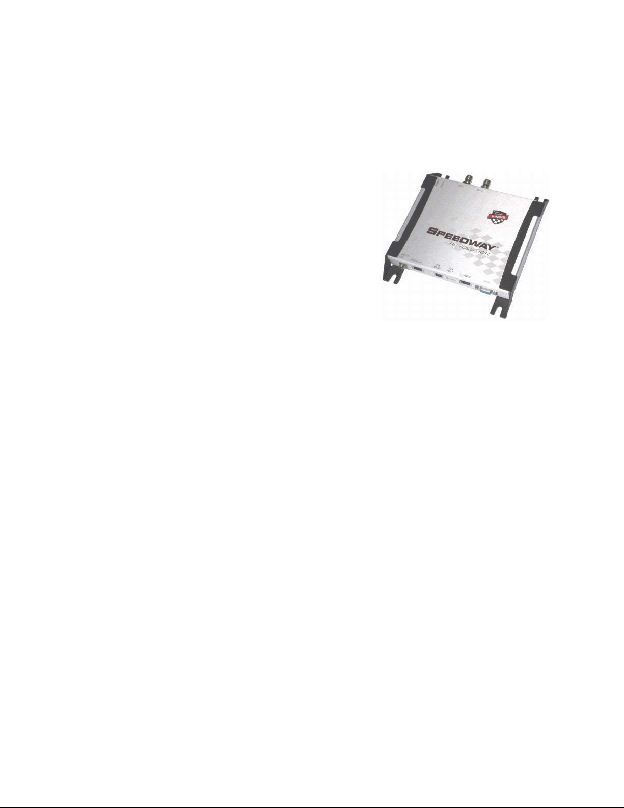
Introduction to Speedway®/Revolution
Speedway®/Revolution (or Speedway/R) is a stationary, small form factor, UHF Gen 2 RFID tag
reader that provides network connectivity between
tag data and enterprise system software. Built on
the industry-leading quality, high performance,
and excellent reliability of Impinj’s original
Speedway reader, Speedway/R includes a variety
of new features that increase its application flexibility:
• Low Power Consumption
With a low power consumption design, Speedway/R can utilize Power over Ethernet (PoE).
Using PoE simplifies deployment and dramatically reduces costs. Speedway/R does
not compromise on performance, however. Even when using PoE, the reader delivers
the full 30 dBm transmit power. Note that Speedway/R supports the IEEE standard
802.3af (for PoE).
• Compact Form Factor
The compact size of Speedway/R (7.4 x 6.9 x 1.2 in) enables ease of installation in
tight spaces and embedded applications.
• Availability of Two Models
Speedway/R offers two models, each with a different number of high performance
monostatic antenna ports. The R220 model is a two-port configuration (shown in the
above photograph), while the R420 is a four-port configuration.
• High Performance Features
Speedway/R utilizes a variety of high performance features making it possible to read
up to 1150 tags per second. These features include Autoset, Low Duty Cycle, dynamic
antenna switching, and receive sensitivity filtering for read zone confinement.
Requirements for Using Speedway/R
This section describes the key requirements for operating and interfacing with a Speedway/R reader.
Environmental Requirements
• Operating temperature: -20 degrees C to +50 degrees C (non-condensing)
• Supported Regions: US, Canada, and other regions following US FCC Part 15 regulations
Copyright © 2009, Impinj, Inc. 2
Page 6

Speedway Revolution Installation and Operations Guide
Hardware Requirements
• TCP/IP network equipment, as required to connect the reader to a PC, Mac, or other
network terminal. If you plan to use PoE, you must have either a power injector or a
network switch that supports PoE.
• Impinj-approved UHF RFID antenna(s), including associating RF cable with RP-TNC
male connector interface
• A computer running Microsoft Windows XP, Vista, or Linux PC, which has:
• an available RS-232 serial port (required only if host system does not support
DHCP)
• Standard, grounded DB9 serial cable (required only if your system does not sup-
port IP provisioning). The Cisco Management Cable (RJ-45 to DB9) is recommended.
• An Ethernet port
• Standard Ethernet cable(s)
Power Requirements
As noted earlier, there are two options for powering your Speedway/R reader: PowerOver-Ethernet (PoE) or an external power supply. PoE offers the most efficient power
consumption and allows up to +30 dBm. An external power supply allows up to +32.5
dBm.
If using a power supply module, you must use a module with +24 VDC output that has the
following part number: IPJ-A2001-000. Use an AC power cord (for North America) that
has the following part number: IPJ-A2051-USA. You can order this power supply and
power cord from Impinj.
Supported Operating Environments
This section describes the environments in which you can access the Speedway/R Rshell
console (for configuring, monitoring, and maintaining the reader). The tools you use to
access the Rshell console depend on how you connect your PC to the reader: serial connection (RS-232) or Ethernet connection (SSH/Telnet). On PCs running Microsoft Windows, you can now use the same tool—Putty—for both types of connections.
Table 1: Speedway/R Operating Environments
Recommended Tools
Interface Protocol
Microsoft Windows Linux
Ethernet SSH—Port 22
Telnet—Port 23
Serial RS-232 Putty (version 0.59
Putty SSH or
Telnet
Minicom
and higher supports
serial)
3 Copyright © 2009, Impinj, Inc.
Page 7

Chapter 1: Introduction
Supported Communication Protocol
For client control of the reader, Speedway/R supports the EPCglobal Low Level Reader
Protocol (LLRP) v1.0.1. LLRP is an EPCglobal standard interface that allows communication with the reader and with EPCglobal Generation 2 (Gen 2) RFID tags.
Antenna Requirements
Depending on the reader model you are installing, Speedway/R is equipped with two
(R220) or four (R420) monostatic antenna ports (independent, bidirectional, and full
duplex TX/RX).
Antenna requirements vary by regulatory region. For details about the requirements in a
specific region, see the relevant antenna section in “Appendix A: Information Specific to
Regions of Operation” on page 19.
Copyright © 2009, Impinj, Inc. 4
Page 8
Speedway Revolution Installation and Operations Guide
Chapter 2: Installing and Connecting Speedway/Revolution
This chapter provides details about the Speedway/R I/O ports and status LEDs and
explains the detailed procedures for installing the reader and connecting it to your network.
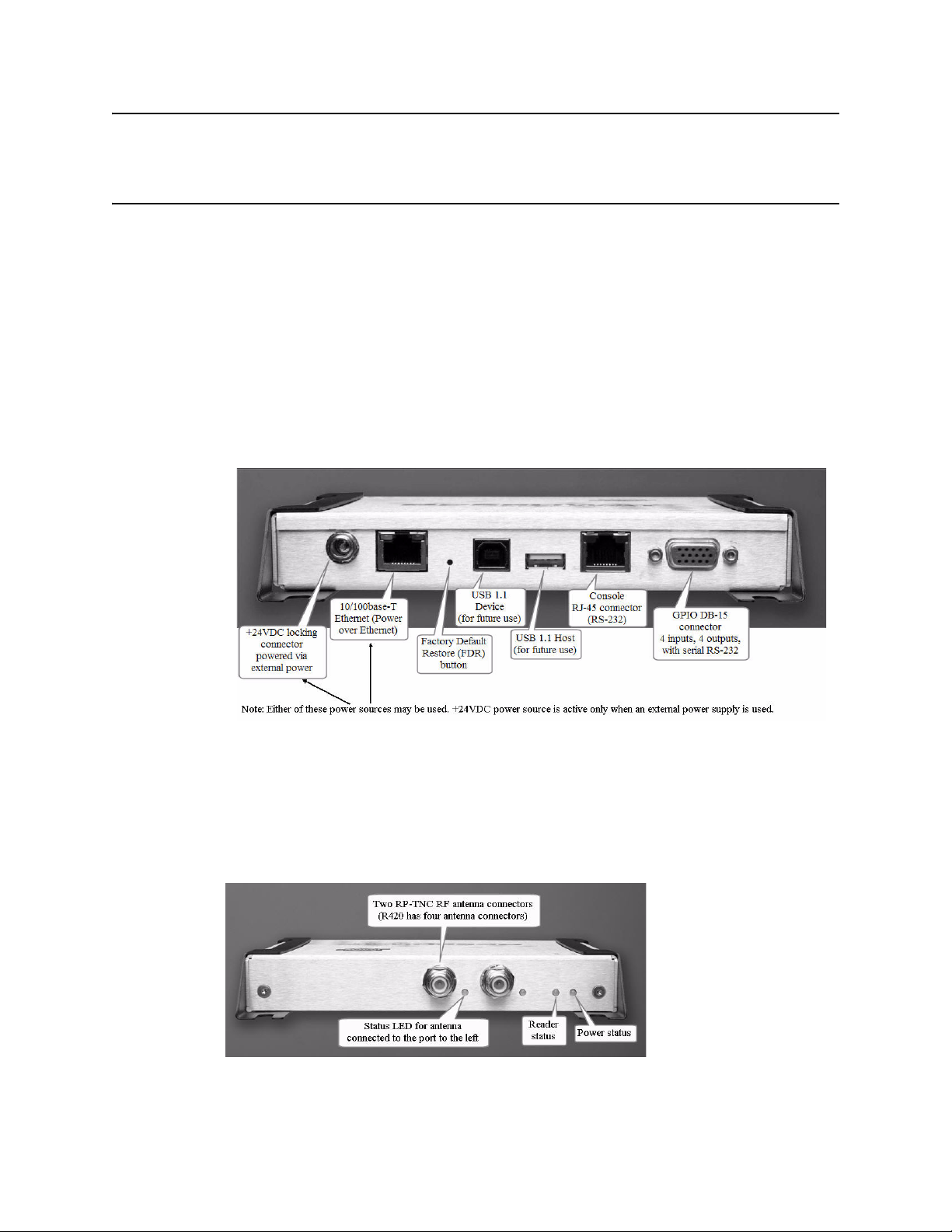
Speedway/R I/O Ports and Status LEDs
The following graphic illustrates the various I/O ports located on the Speedway/R reader.
This graphic illustrates a Speedway R420, which includes four antenna ports (not visible
in this graphic). Note that Speedway R220 includes two antenna ports. Other than that difference, however, the exterior ports are the same on both models.
Figure 1: Impinj Speedway/R Port Connections
Note:
For details on the function and electrical specifications for each pin of the GPIO DB-15
connector, see “Appendix B: GPIO Details” on page 23.
Antenna Ports and Status LEDs
On the back side of the reader are the antenna ports and LED status indicators. The following graphic (of an R220) illustrates their locations:
5 Copyright © 2009, Impinj, Inc.
Page 9

Chapter 2: Installing and Connecting Speedway/Revolution
The following table describes the LED behavior for various reader states:
Table 2: Reader Operations and Associated Status LED Behavior
Reader Operation LED Expected Behavior
Startup (power on),
normal completion
Startup (reset),
normal completion
Startup (failure) Hardware problems
Power applied, attempting
to start boot code
Bootloader running Power Blinking green (1Hz)
Bootloader calling firmware image
Bootloader completed successfully, reader is ready
Factory Default Restore
(FDR) button pressed
FDR button pressed for 3
seconds
detected, unable to boot
Power Solid red
Status Off
Status Off
Power Solid green
Status Off
Power Solid green
Status Solid green
Power Turns off
Status Off
Power Blinks twice (red), indi-
cates a configuration
default restore will occur
Status Off
Power Continuous blinking red
Status Off
Detection of
antenna activity
Copyright © 2009, Impinj, Inc. 6
Detects no activity on
antenna port
Detects antenna transmission activity on antenna
port
Antenna Off
Antenna Solid green
Page 10

Speedway Revolution Installation and Operations Guide
Overview of Installation and Connection Process
Listed below are the primary steps to follow to install and connect Speedway/R:
1. Position the reader appropriately for your environment. This may or may not involve
mounting the reader.
2. Connect the antenna(s) to the appropriate ports on the reader.
3. Connect the reader to the network.
4. Connect power to the reader.
5. Using the MultiReader application, read some tags with your newly-installed reader.
Detailed Installation Procedures
This section provides the details for each step listed above.
Step 1: Position the Speedway/R reader
Choose the appropriate location for the reader. Generally speaking, you should always
keep the unit away from direct sunlight, high humidity, extreme temperatures, vibration,
and sources of electromagnetic interference. Any combination of these conditions may
degrade performance or shorten the life of the unit. Also, if you plan to power the reader
using an external power supply, confirm that there is a standard 120 or 220 VAC outlet
nearby. To minimize power loss, it is best to position the reader within 100 meters of its
power source. To learn more about choosing the appropriate location for maximizing the
performance and efficiency of your reader, see the Impinj System Design Guide.
Caution:
Mounting the Reader
Depending on your environment, you may need to mount the reader to a wall or another object.
To mount the Speedway/R reader:
1. Locate the four mounting slots on the reader, as illustrated below:
2. Using 1/4” - 20 or M6 screws, secure the unit. You can mount the reader horizontally
or vertically.
If there is any chance of dust or water exposure, you should mount the reader so that digital I/O ports are facing down to prevent ingress.
7 Copyright © 2009, Impinj, Inc.
Page 11

Chapter 2: Installing and Connecting Speedway/Revolution
Step 2: Connect the Antenna(s) to the Speedway/R Reader
Depending on the Speedway/R model you are installing, the reader has either two antenna
ports (Speedway R220) or four antenna ports (Speedway R420). Each port is independent,
bidirectional, and full duplex TX/RX (monostatic). It is recommended that you connect
the antenna(s) before powering on the reader.
Warning:
You must use Impinj-approved antennas with Speedway/R. See “Appendix A: Information Specific to Regions of Operation” on page 19 for a detailed list of approved vendors.
Using any other antenna may damage the reader or adversely affect performance. Speedway/R requires professional installation to correctly set the TX power for the RF cable and
antenna selected.
To connect the antenna(s) to Speedway/R:
1. Position each reader antenna, keeping the following points in mind:
• Position the antenna(s) to achieve the most effective and efficient tag reads. For
details on the best layouts for various environments, see the Impinj System Design
Guide.
• Position the antenna(s) to maximize operator safety. Personnel who will be in the
area for prolonged periods of time should be able to remain at a safe distance at all
times. See “Appendix A: Information Specific to Regions of Operation” on
page 19 for the specific requirements for your regularity region.
2. Mount the antenna(s) according to the instructions provided by the antenna manufacturer.
3. Attach the antenna cable(s) to the antenna port(s) on the reader. You can choose any
port for any antenna.
4. Finger tighten the connection, making sure it is secure. A loose connection negatively
impacts the performance of the antenna.
Caution:
Impinj has designed its antenna ports to be self-terminating. Therefore, it is important that
you do not terminate unused antenna ports. Leave them unconnected.
Step 3: Connect Speedway/R to the Network
You are now ready to connect the installed Speedway/R to your network. You have two
options:
• If your network supports DHCP, you can connect the reader directly to your Ethernet
network and, once the reader is powered, immediately communicate with it via Telnet
(TCP/IP).
• If your network does not support DHCP you will need to connect a PC directly to the
reader using a serial connection (RS-232), then use the reader’s Rshell command line
interface to configure a static IP address for the reader. At that point you will be able
to connect the reader to your Ethernet network.
Copyright © 2009, Impinj, Inc. 8
Page 12

Speedway Revolution Installation and Operations Guide
The details of completing each connection option are discussed below. Before proceeding,
however, take note of the reader’s factory default network settings:
Table 3: Default Network Settings
Setting Description
hostname Speedway-XX-XX-XX where XX-XX-XX is the last three
bytes of the reader’s MAC address (which is printed on the version label attached to the reader enclosure)
DHCP Enabled. The reader also reports its hostname to the DHCP
server.
To connect Speedway/R to the Ethernet network:
• Using a standard Ethernet cable, connect the RJ-45 connector on the reader to a LAN
drop or network switch. A typical network configuration is illustrated below:
If your network switch is PoE-enabled, the reader will power on when you connect it
to the network. See “Step 4: Power the Reader” on page 11 for information on what to
expect.
Note:
9 Copyright © 2009, Impinj, Inc.
If you need to connect a PC directly to the Ethernet port, you can use a standard Ethernet cable. A crossover cable is not necessary.
Page 13

Chapter 2: Installing and Connecting Speedway/Revolution
To connect Speedway/R to your PC over a serial connection:
1. If necessary, download the latest version of Putty, which is a free and reliable SSH,
Telnet, and serial client. Version 0.59 or higher contains support for serial connections.
2. Using a standard, grounded DB9 serial cable, connect your PC’s valid/active COM
port to the serial port on the reader, as illustrated below:
3. Power the reader and wait for the boot sequence to complete. (See “Step 4: Power the
Reader” on page 11.)
4. On the PC, run the Putty application and select the Serial connection option. Verify
that Serial line to connect to is set to COM1 (if that is correct for your PC). Set
Speed to 115200. Set Flow control to None.
5. Click Open. The Rshell console window opens.
6. Log in with the following default credentials (unless they have been changed):
User Name: root
Password: impinj
7. When the Rshell command line prompt appears, you can begin configuring the network settings for the reader. See “Using Rshell to Configure Network Settings for
Speedway/R” on page 13 for details.
8. When you have completed configuration of the appropriate network settings, connect
the reader to your Ethernet network as described on page 9.
Note:
Copyright © 2009, Impinj, Inc. 10
If you decide to connect to DHCP after connecting serially, remember to use Rshell to
change the IP address on the reader from static to dynamic. See “Using Rshell to Configure Network Settings for Speedway/R” on page 13 for details.
Page 14

Speedway Revolution Installation and Operations Guide
Step 4: Power the Reader
You have two choices for powering Speedway/R:
• Power over Ethernet (PoE)
• External power supply
If you are using PoE, your reader began receiving power when you connected it to the network in the previous step. Therefore, there is nothing more you need to do. If you are
using an external power supply, connect the AC power plug into a suitable 100-240 VAC,
50-60 Hz power outlet.
In either case, when power is supplied to the reader, it begins its boot sequence. This
sequence typically completes within 30 to 45 seconds. Until the boot sequence completes,
the reader will not accept commands. The Power and Status LEDs on the reader alert you
to what is happening. See the table labeled “Reader Operations and Associated Status
LED Behavior” on page 6 for details.
Important:
If a reader is receiving its power via PoE and it detects that an external power supply has
been connected, the reader reboots and switches its power source from PoE to the external
power supply. If, however, the reader is receiving power via an external power supply and
it detects the connection to a PoE-enabled network switch, nothing changes. The reader
continues to receive its power from the external supply. Because the external power supply is capable of higher power than PoE, it always takes precedence if both sources are
connected.
Step 5: Use the MultiReader Application to Read Some Tags
To be completed later.
11 Copyright © 2009, Impinj, Inc.
Page 15

Chapter 2: Installing and Connecting Speedway/Revolution
Copyright © 2009, Impinj, Inc. 12
Page 16

Speedway Revolution Installation and Operations Guide
Chapter 3: Configuring Speedway/ Revolution
This chapter will be completed later. It will include topics such as those listed below:
Configuration Overview
Using Rshell to Configure Network Settings for Speedway/R
Configuring the RFID Behavior of Speedway/R
13 Copyright © 2009, Impinj, Inc.
Page 17

Chapter 3: Configuring Speedway/Revolution
Copyright © 2009, Impinj, Inc. 14
Page 18

Speedway Revolution Installation and Operations Guide
Chapter 4: Monitoring Speedway/ Revolution
This chapter will be completed later. It will contain such topics as follows:
Using Rshell to Monitor Speedway/R
Viewing Speedway/R Logs
15 Copyright © 2009, Impinj, Inc.
Page 19

Chapter 4: Monitoring Speedway/Revolution
Copyright © 2009, Impinj, Inc. 16
Page 20

Speedway Revolution Installation and Operations Guide
Chapter 5: Troubleshooting
This chapter will be completed later.
17 Copyright © 2009, Impinj, Inc.
Page 21

Chapter 5: Troubleshooting
Copyright © 2009, Impinj, Inc. 18
Page 22

Speedway Revolution Installation and Operations Guide
Appendix A: Information Specific to Regions of Operation
Speedway/R is designed to work in various regulatory regions. This appendix includes
frequency ranges and antenna requirements specific to each supported region. Note that
this first release of Speedway/R covers operation in North America only.
Important
For each region, the reader is locked such that it can operate only in the specific frequencies for that region. The region-specific frequencies are listed in this appendix.
Operation in North America
Frequency Plan
The FCC specifies frequency hopping across the North American spectrum allocated to
UHF RFID (902–928 MHz, with hopping occurring between 902.75–927.25 MHz in 500
KHz steps). This is further explained in the table below:
Table 4: Frequency Plan for North America
Transmit Channel Number Center Frequency (MHz)
1 902.75
2 903.25
3 903.75
4 904.25
.
.
.
.
.
.
49 926.75
50 927.25
Antenna Requirements
Positioning
Position the antenna such that personnel who will be in the area for prolonged periods of
time can remain at least 25 centimeters from the antenna’s surface. This is required by the
FCC. For more details, see the following FCC bulletins:
• FCC OET Bulletin 65: Evaluating Compliance with FCC Guidelines for Human
Exposure to Radiofrequency Electromagnetic Fields
• FCC OET Bulletin 56: Questions and Answers about Biological Effects and
Potential Hazards of Radiofrequency Electromagnetic Fields
19 Copyright © 2009, Impinj, Inc.
Page 23

Appendix A: Information Specific to Regions of Operation
Installation
Because Speedway/R is capable of up to +32.5 dBm conducted power on the housing RF
connector, professional installation is required.
Power
Speedway/R may only be operated with Impinj-approved antennas and can radiate no
more than 36 dBm EIRP (Equivalent Isotropically Radiated Power) per FCC Part 15.247
regulations. The Speedway/R output power may be increased to provide the maximum
allowable EIRP subject to a maximum conducted power allowance as well. The maximum
conducted power at the antenna connector can be no more than 30 dBm. The maximum
allowable output power of the reader can be set to satisfy both the conductor and radiated
maximum criteria. The expression for the maximum reader power setting is:
Maximum power setting (in dBm)
= The Smaller of
(36 - Composite Antenna Gain (in dBm))
OR
(30 + Cable Loss (in dBm)),
where the composite antenna gain comprises the maximum linear antenna gain in dBi
minus any cable loss between the reader and antenna in dB. Approved antenna vendors,
model numbers, and associated gain are listed in the next section.
Approved Antenna Vendors
• Cushcraft model number S9028PCL/R (left- or right-hand CP), with integrated 8 foot
pigtail to RP-TNC male connector; 6 dBi composite gain
• Impinj model number IPJ-A0301-USA (Mini-Guardrail) with SMA female connector;
-15 dBi gain
• Impinj model number IPJ-A0310-USA (Threshold-T Antenna) with 12 inch integrated pigtail to BNC male connector, 6 dBi composite gain.
• Impinj model number IPJ-A0400-USA, CSL CS-777-2 (Brickyard) with 7 foot integrated pigtail to RP-TNC male connector; 2 dBi composite gain
• Impinj model number IPJ-A0401-USA or IPJ-A0402-USA (both Guardwall) with 6
foot integrated pigtail to RP-TNC male connector; 6 dBi composite gain
• MA/COM MAAN-000246-FL1 integrated RFID floor-mounted stand (multiple configurations available, 2 or 4 antennas left-hand and right-hand CP) with 8 foot integrated pigtail to RP-TNC male connector; 6 dBi composite gain
• MA/COM MAAN-000246-WL1 integrated RFID wall-mounted stand (multiple configurations available, 2 antennas left-hand and right-hand CP) with 8 foot integrated
pigtail to RP-TNC male connector; 6 dBi composite gain
• MTI MT-262006/TLH (left-hand CP) or MT-262006/TRH (right-hand CP) with RPTNC female connector (antennas available in IP54 or IP67 ratings); 6 dBi gain
• MTI MT-262013/NLH (left-hand CP) or MT-262013/NRH (right-hand CP) with Ntype female connector (antennas available in IP54 or IP67 ratings); 4.5 dBi gain
• MTI MT-262013/TLH (left-hand CP) or MT-262013/TRH (right-hand CP) with RPTNC female connector (antennas available in IP54 or IP67 ratings); 4.5 dBi gain
Copyright © 2009, Impinj, Inc. 20
Page 24

Speedway Revolution Installation and Operations Guide
• Sensormatic Electronics Corp. model number IDANT20TNA25 with 25 foot Belden
7806A RG-58 coaxial cable (0.1 dB per foot loss) to RP-TNC male connector; 5.5 dBi
composite gain
• Sensormatic Electronics Corp. model number IDANT10CNA25 with 25 foot Belden
7806A coaxial cable (0.1 dB per foot loss) to RP-TNC male connector; 3.5 dBi composite gain
• Sensormatic Electronics Corp. model number IDANT10CNA25 with 6 foot Belden
7806A coaxial cable (0.1 dB per foot loss) to RP-TNC male connector; 5.4 dBi composite gain
Warning
The use of any antenna not listed above may damage the reader or adversely affect performance.
21 Copyright © 2009, Impinj, Inc.
Page 25

Appendix A: Information Specific to Regions of Operation
Copyright © 2009, Impinj, Inc. 22
Page 26

Speedway Revolution Installation and Operations Guide
Appendix B: GPIO Details
The following graphic shows the detailed function of each pin of the GPIO DB-15 connector.
Figure 2: DB-15 GPIO Port
Note:
Both the input and output pins are opto-isolated.
The following tables further explain the function of each pin.
Table 5: DB-15 Connector Pin-Out
Pin I/O Name I/O Function
1 +5V Supply Reader supplied (not isolated) power source
2 RS-232 RX For auxilliary serial port functions
3 RS-232 TX For auxilliary serial port functions
4 Processor Reset A hard reboot into the reader
(Pulling this line low performs the same function as
pressing the FDR button—see Table 2 on page 6 for
details.)
5 V+ Power source for isolated outputs
6 V- Return for isolated inputs and outputs
7 Ground Reader (not isolated) return
8 User OUT 1 Isolated output 1 (active pull down to V-)
9 User OUT 2 Isolated output 2 (active pull down to V-)
10 User OUT 3 Isolated output 3 (active pull down to V-)
11 User OUT 4 Isolated output 4 (active pull down to V-)
12 User IN 1 Isolated input 1
13 User IN 2 Isolated input 2
23 Copyright © 2009, Impinj, Inc.
Page 27

Appendix B: GPIO Details
Table 5: DB-15 Connector Pin-Out
Pin I/O Name I/O Function
14 User IN 3 Isolated input 3
15 User IN 4 Isolated input 4
Table 6: GPIO Interface Electrical Specification
Pin Parameter Description Min Max Unit Conditions
+5V Supply I
User IN 1-4 V
User IN 1-4 V
User IN 1-4 I
User IN 1-4 V
User OUT 1-4 V
User OUT 1-4 V
User OUT 1-4 V
*User-supplied voltage
O
LI
IH
IL
I
OH
OL
I
Output current 200 mA
HIGH level input voltage 3 30 V
LOW level input voltage 0 2 V
Input current 5 mA 24V input
Input voltage range 0 30 V No damage
Output high voltage V+* V 10k pullup
Output low voltage Vol+5 V 200mA load
Operating voltage range 40 V
Copyright © 2009, Impinj, Inc. 24
 Loading...