

Impex MD-8870 Owner's Manual
NOTE:
Please read all instructions
carefully before using this
product
Table of Contents
Safety Notice
Hardware Identifier
Assembly Instruction
Parts List
Warranty
Ordering Parts
MARCY® DIAMOND
DELUXE CAGE
MD-8870
Model
MD-8870
Retain This
Manual for
Reference
100712
OWNER'S
MANUAL
IMPEX® INC.
14777 DON JULIAN RD., CITY OF INDUSTRY, CA 91746
Tel: (800) 999-8899 Fax: (626) 961-9966
www.impex-fitness.com
info@impex-fitness.com

TABLE OF CONTENTS
BEFORE YOU BEGIN…………………………………………………………….. 1
IMPORTANT SAFETY NOTICES……………………………………………….. 2
CAGE HARDWARE PACK………………………………………………………. 4
CAGE ASSEMBLY INSTRUCTIONS…………………………………………… 6
EXPLODED DIAGRAM…………………………………………………………… 21
CAGE PARTS LIST………………………………………………………………. 22
MULTI-PURPOSE BENCH HARDWARE PACK……………………………… 23
MULTI-PURPOSE BENCH ASSEMBLY INSTRUCTIONS………………….. 26
EXPLODED DIAGRAM………………………………………………………….. 30
MULTI-PURPOSE BENCH PARTS LIST……………………………………… 31
WEIGHT RESISTANCE CHART……………………………………………….. 32
WARRANTY……………………………………………………………………… 33
ORDERING PARTS…………………………………………………………….. 33
BEFORE YOU BEGIN
Thank you for selecting the MARCY
your safety and benefit, read this manual carefully before using the machine.
As a manufacturer, we are committed to provide you complete customer
satisfaction. If you have any questions, or find there are missing or damaged
parts, we guarantee you complete satisfaction through direct assistance from
our factory. To avoid unnecessary delays, please call our TOLL-FREE
customer service number. Our Customer Service Agents will provide immediate
assistance to you.
®
DIAMOND MD-8870 by IMPEX® INC. For
Toll-Free Customer Service Number
1-800-999-8899
Mon. - Fri. 9 a.m. - 5 p.m. PST
www.impex-fitness.com
info@impex-fitness.com
1

IMPORTANT SAFETY NOTICE
PRECAUTIONS
This exercise machine is built for optimum safety. However, certain precautions apply
whenever you operate a piece of exercise equipment. Be sure to read the entire manual before
you assemble or operate your machine. In particular, note the following safety precautions:
1. Keep children and pets away from the machine at all times. DO NOT
leave children unattended in the same room with the machine.
2. Only one person at a time should use the machine.
3. If the user experiences dizziness, nausea, chest pain, or any other abnormal
symptoms, STOP the workout at once. CONSULT A PHYSICIAN IMMEDIATELY.
4. Position the machine on a clear, leveled surface. DO NOT use the machine
near water or outdoors.
5. Keep hands away from all moving parts.
6. Always wear appropriate workout clothing when exercising. DO NOT wear
robes or other clothing that could become caught in the machine. Running
or aerobic shoes are also required when using the machine.
7. Use the machine only for its intended use as described in this manual. DO
NOT use attachments not recommended by the manufacturer.
8. Do not place any sharp object around the machine.
9. Disabled person should not use the machine without a qualified person or
physician in attendance.
10. Before using the machine to exercise, always do stretching exercises to
properly warm up.
11. Never operate the machine if the machine is not functioning properly.
12. A spotter is recommended during exercise.
CARE AND MAINTENANCE
1. Lubricate moving parts with WD-40 or light oil periodically.
2. Inspect and tighten all parts before using the machine.
3. The machine can be cleaned using a damp cloth and mild non-abrasive detergent.
DO NOT use solvents.
4. Maximum user’s weight: 300 lbs.
5. Maximum weights on the Weight Bar: 300 lbs.
6. Maximum weights on Leg Developer: 100 lbs.
7. Maximum weights on Lat Pull: 100 lbs.
WARNING: BEFORE BEGINNING ANY EXERCISE PROGRAM, CONSULT YOUR
PHYSICIAN. THIS IS ESPECIALLY IMPORTANT FOR INDIVIDUALS OVER THE
AGE OF 35 OR PERSONS WITH PRE-EXISTING HEALTH PROBLEMS. READ ALL
INSTRUCTIONS BEFORE USING ANY FITNESS EQUIPMENT. IMPEX INC.
ASSUMES NO RESPONSIBILITY FOR PERSONAL INJURY OR PROPERTY
DAMAGE SUSTAINED BY OR THROUGH THE USE OF THIS PRODUCT.
SAVE THESE INSTRUCTIONS.
2
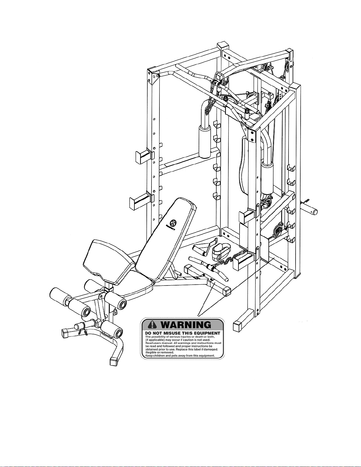
WARNING LABEL PLACEMENT
The warning labels shown here have been placed on the Rear Base, and Bench Rear Stabilizer. If the
labels are missing or illegible, please call customer service at 1-800-888-8899 for replacements. Apply
the labels in the location shown.
3
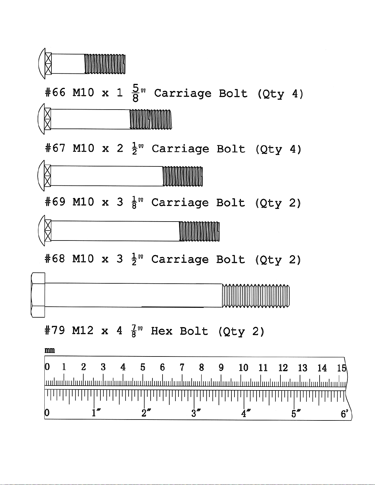
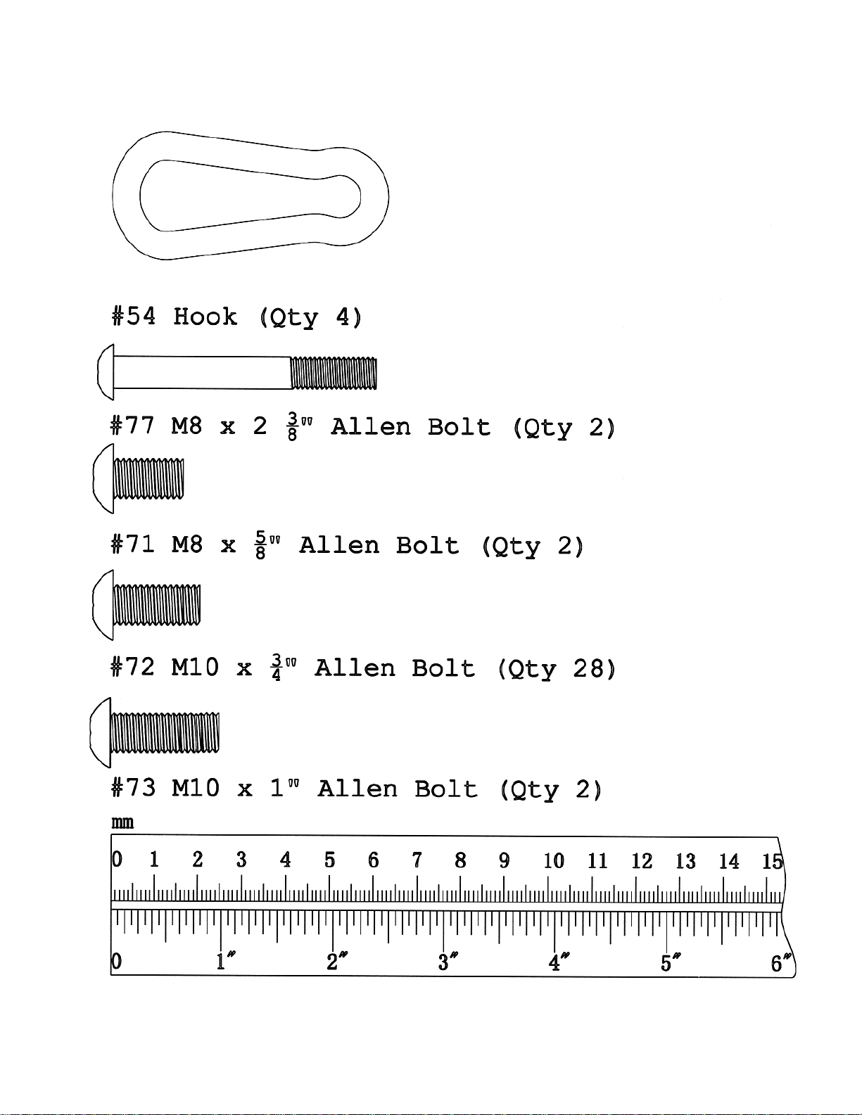
CAGE HARDWARE PACK
NOTE: The following parts are not drawn to scale. Please use your own ruler to measure the size.
4
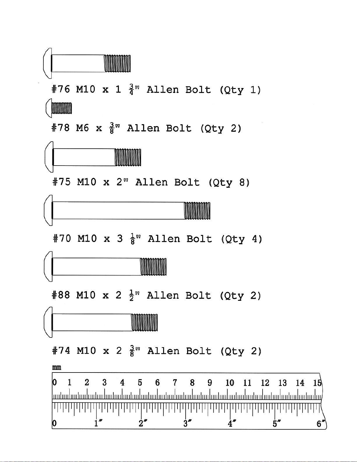
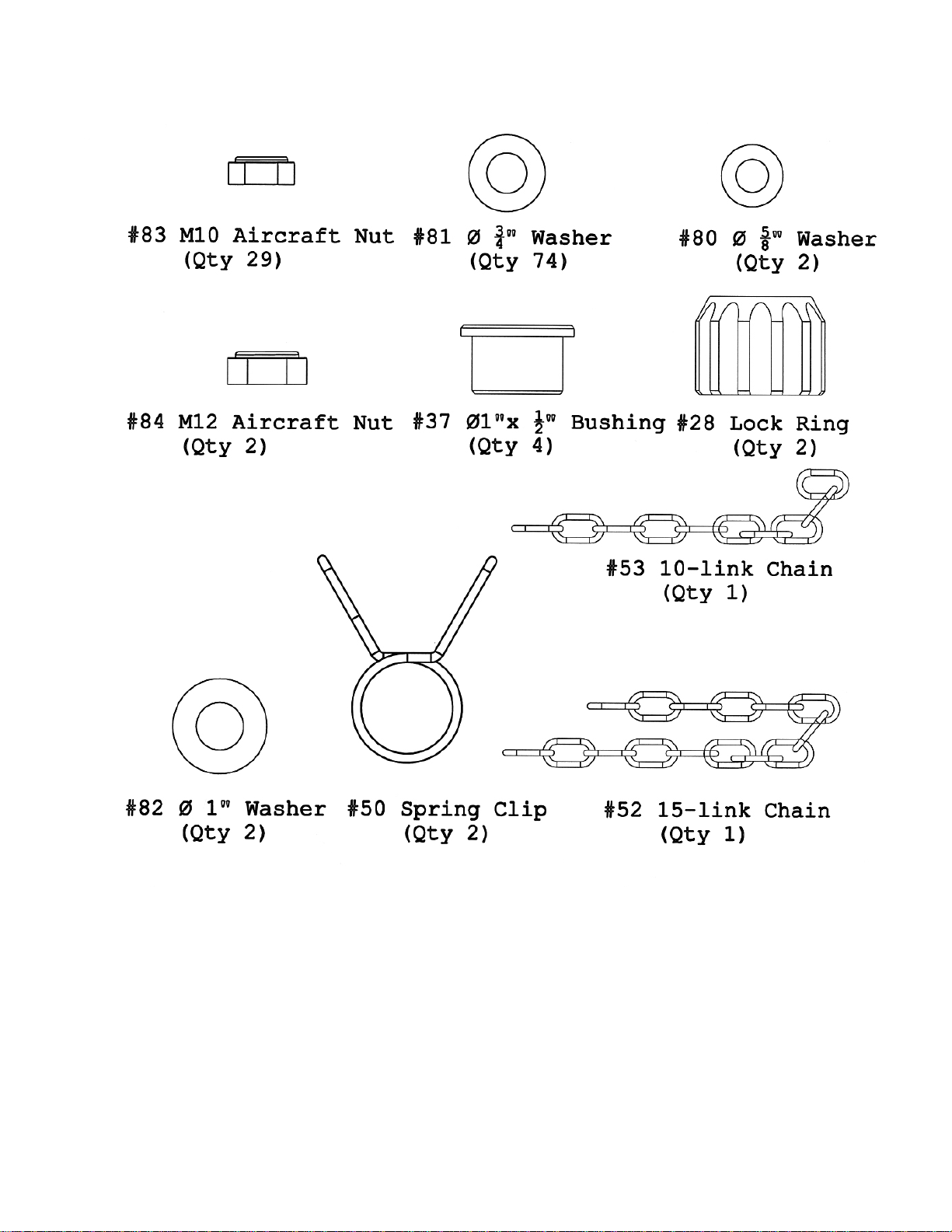
CAGE HARDWARE PACK
NOTE: The following parts are not drawn to scale. Please use your own ruler to measure the size.
5
CAGE HARDWARE PACK
NOTE: The following parts are not drawn to scale. Please use your own ruler to measure the size.
6
CAGE HARDWARE PACK
7
CAGE ASSEMBLY INSTRUCTION
Tools Required Assembling the Machine: Two Adjustable Wrenches and Allen
Wrenches.
NOTE: It is strongly recommended that two or more people assemble this machine to
avoid possible injury.
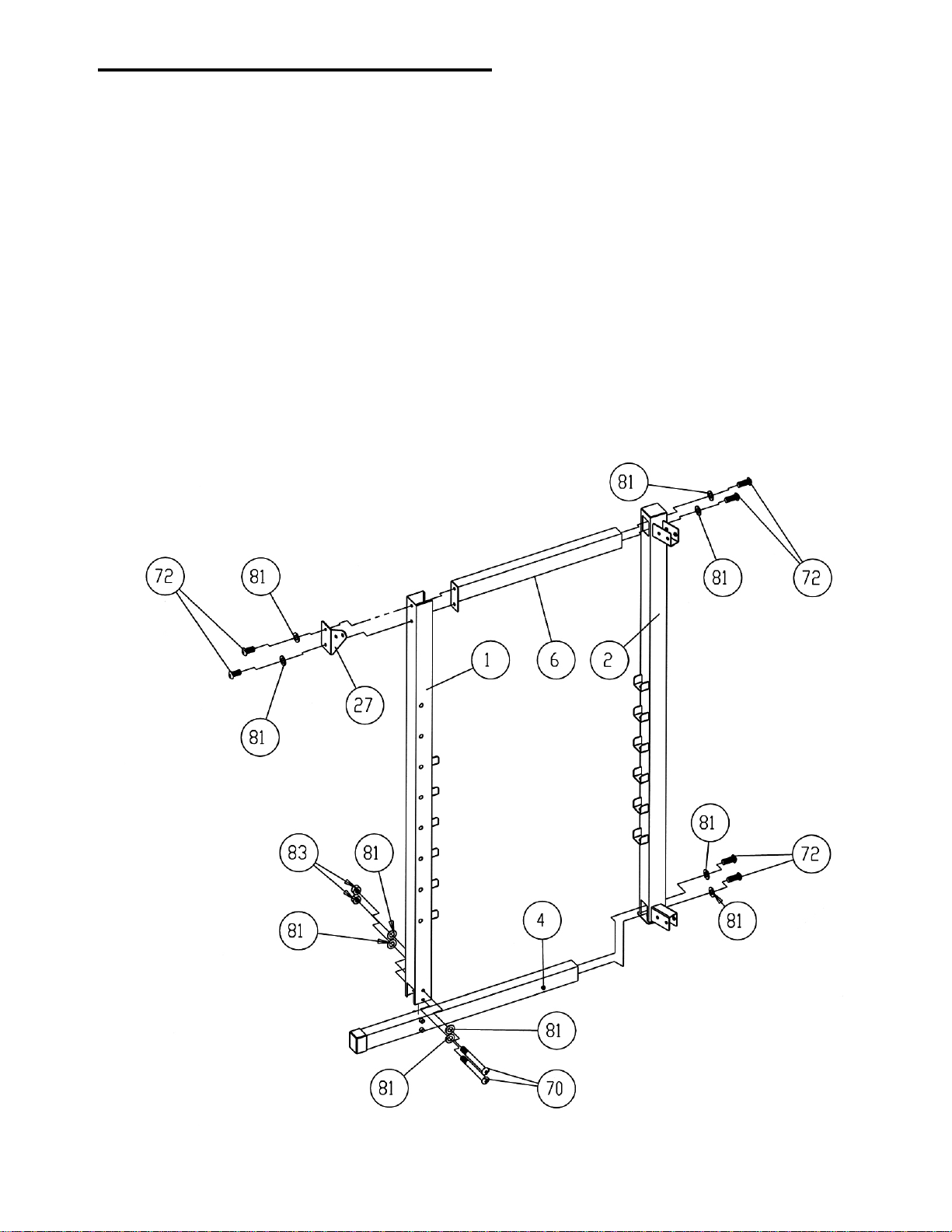
STEP 1 (See Diagram 1)
A.) Do not tighten Nuts and Bolts until instructed to do so.
B.) Insert a Side Base Frame (#4) into the Rear Right Vertical Frame (#2). Secure it with two
M10 x ¾” Allen Bolts (#72) and two Ø ¾” Washers (#81).
C.) Attach a Front Vertical Frame (#1) onto the Side Base Frame. Secure it with two M10 x 3
1/8” Allen Bolts (#70), four Ø ¾” Washers (#81), and two M10 Aircraft Nut (#83).
D.) Attach the front of Side Upper Frame (#6) to Front Vertical Frame. Secure it with two M10
x ¾” Allen Bolts (#72), one Right Chin-up Bracket (#27), and two Ø ¾” Washers (#81).
E.) Attach the rear of Side Upper Frame to the Rear Right Vertical Frame. Secure it with two
M10 x ¾” Allen Bolts (#72) and two Ø ¾” Washers (#81).
DIAGRAM 1
8
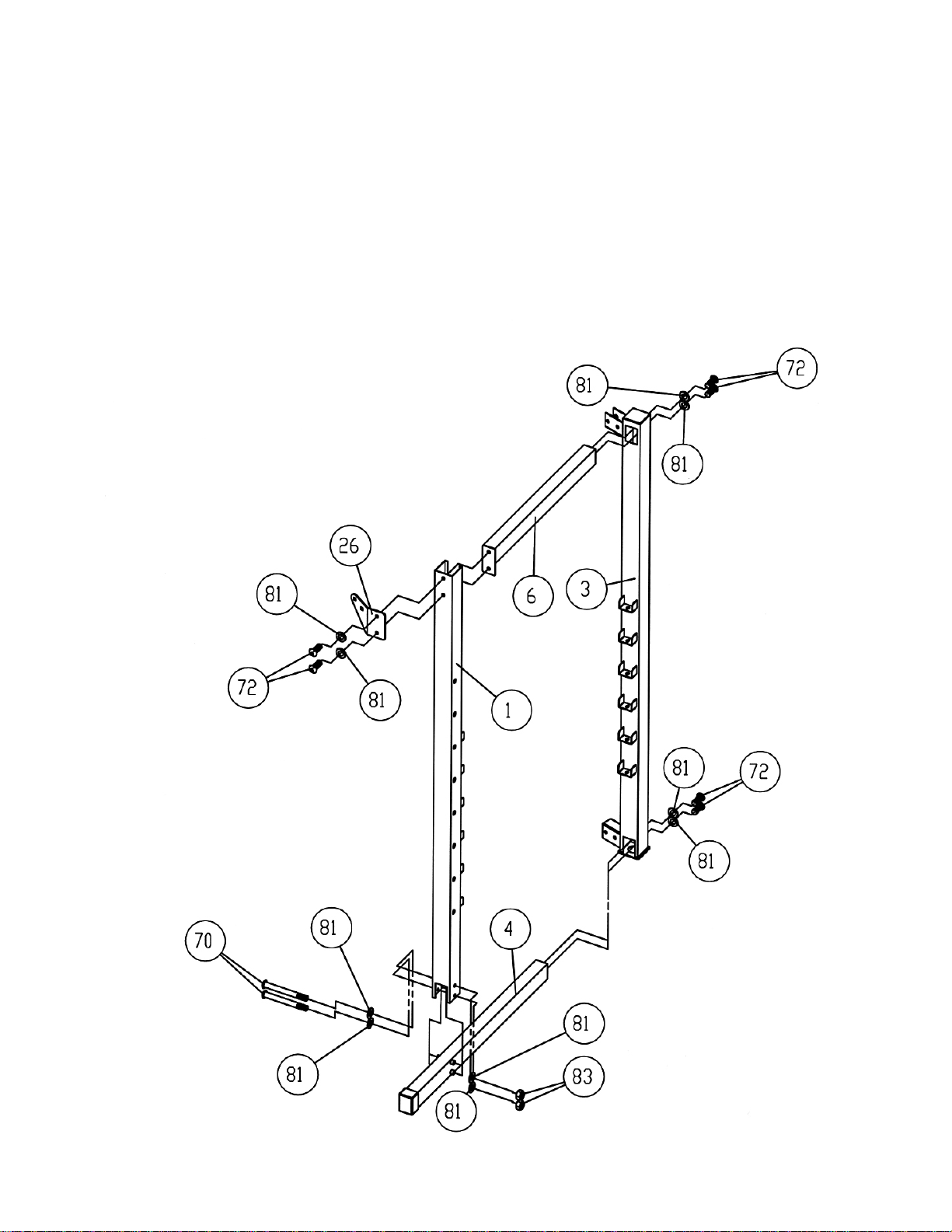
STEP 2 (See Diagram 2)
A.) Do not tighten the Nuts and Bolts until instructed to do so.
B.) Insert a Side Base Frame (#4) into the Rear Left Vertical Frame (#3). Secure it with two
M10 X ¾” Allen Bolts (#72) and two Ø ¾” Washers (#81).
C.) Attach a Front Vertical Frame (#1) onto the Side Base Frame. Secure it with two M10 x 3
1/8” Allen Bolts (#70), four Ø ¾” Washers (#81), and two M10 Aircraft Nuts (#83).
D.) Attach the front of a Side Upper Frame (#6) to the Front Vertical Frame. Secure it with two
M10 x ¾” Allen Bolts (#72), one Left Chin-up Bracket (#26), and two Ø ¾” Washers (#81).
E.) Attach the rear of the Side Upper Frame to the Rear Left Vertical Frame. Secure it with
two M10 x ¾” Allen Bolts (#72) and two Ø ¾” Washers (#81).
DIAGRAM 2
9

STEP 3 (See Diagram 3)
A.) Do not tighten all Nuts and Bolts until instructed to so.
B.) Attach the Rear Base Frame (#7) to the Rear Right & Left Vertical Frame (#2 & #3).
C.) Secure each end with four M10 x ¾” Allen Bolts (#72) and four Ø ¾” Washers (#81).
D.) Attach the Middle Vertical Frame (#8) onto the Rear Base Frame. Attach the Foot Plate
(#35) to front Middle Vertical Frame. Attach the Lower Pulley Frame (#15) to the Middle
Vertical Frame from rear. Secure them together with two M10 x 3 1/8” Carriage Bolts
(#69), two Ø ¾” Washers (#81), and two M10 Aircraft Nuts (#83).
E.) Attach the Rear Upper Frame (#5) to the Middle Vertical Frame; Rear Left Vertical Frame,
and Rear Right Vertical Frame.
F.) Repeat C to secure the Rear Upper Frame to Rear Left and Right Vertical Frame.
G.) Attach the Lat Bar Frame (#17) onto the Rear Upper Frame. Secure the Lat Bar Frame;
Rear Upper Frame, and the Middle Vertical Frame together with two M10 x 3 ½” Carriage
Bolts (#68), two Ø ¾” Washers (#81), and two M10 Aircraft Nuts (#83).
H.) Attach the Chin-up Bar (#25) to the Left & Right Chin-up Bracket (#26 & #27). Secure
each end with two M10 x 1 5/8” Carriage Bolts (#66), two Ø ¾” Washers (#81), and two
M10 Aircraft Nuts (#83).
10
 Loading...