

Page 1
NOTE:
Please read all instructions
carefully before using this
product
Table of Contents
Safety Notice
Hardware Pack
Assembly Instruction
Parts List
Warranty
Ordering Parts
Deluxe Recumbent Bike
BF-6731A
Model
BF-6731A
Retain This
Manual for
Reference
07-08-09
OWNER'S
MANUAL
IMPEX® INC.
14777 DON JULIAN RD., CITY OF INDUSTRY, CA 91746
Tel: (800) 999-8899 Fax: (626) 961-9966
www.impex-fitness.com
info@impex-fitness.com
Page 2

TABLE OF CONTENTS
BEFORE YOU BEGIN...................................................................................…. 1
IMPORTANT SAFETY NOTICES..................................................................…. 2
HARDWARE PACK……….....…....................................................................…. 4
ASSEMBLY INSTRUCTIONS........................................................................…. 5
EXPLODED DIAGRAM………………………………………………………………. 11
PARTS LIST...................................................................................................… 12
WARRANTY.................................................................................................…. 13
ORDERING PARTS.....................................................................................….. 13
BEFORE YOU BEGIN
Thank you for selecting the BODY FIT Deluxe Recumbent Bike BF-6731A by IMPEX
INC. For your safety and benefit, read this manual carefully before using the machine.
As a manufacturer, we are committed to provide you complete customer satisfaction.
If you have any questions, or find there are missing or damaged parts, we guarantee
you complete satisfaction through direct assistance from our factory. To avoid
unnecessary delays, please call our TOLL-FREE customer service number. Our
Customer Service Agents will provide immediate assistance to you.
®
Toll-Free Customer Service Number
1-800-999-8899
Mon. - Fri. 9 a.m. - 5 p.m. PST
www.impex-fitness.com
info@impex-fitness.com
1
Page 3

IMPORTANT SAFETY NOTICE
PRECAUTIONS
This exercise machine is built for optimum safety. However, certain precautions apply
whenever you operate a piece of exercise equipment. Be sure to read the entire manual
before you assemble or operate your machine. In particular, note the following safety
precautions:
1. Keep children and pets away from the machine at all times. DO NOT leave
children unattended in the same room with the machine.
2. Only one person at a time should use the machine.
3. If the user experiences dizziness, nausea, chest pain, or any other abnormal symptoms,
STOP the workout at once. CONSULT A PHYSICIAN IMMEDIATELY.
4. Position the machine on a clear, leveled surface. DO NOT use the machine near water
or outdoors.
5. Keep hands away from all moving parts.
6. Always wear appropriate workout clothing when exercising. DO NOT wear robes or
other clothing that could become caught in the machine. Running or aerobic shoes are
also required when using the machine.
7. Use the machine only for its intended use as described in this manual. DO NOT use
attachments not recommended by the manufacturer.
8. Do not place any sharp object around the machine.
9. Disabled person should not use the machine without a qualified person or physician in
attendance.
10. Before using the machine to exercise, always do stretching exercises to properly warm
up.
11. Never operate the machine if the machine is not functioning properly.
12. The Maximum Weight Capacity is 300 lbs.
13. Read all warnings posted on the exercise bike.
14. Inspect the exercise bike for worn or loose component prior to use. Tighten/replace any
loose or wore components prior to use.
15. Care should be taken in mounting or dismounting the exercise bike.
16. This exercise bike is for consumer and home use only.
Maintenance and Storage
1. Inspect and tighten all parts each tim e you use the m achine. Replace any worn parts im mediately.
2. The bike can be cleaned using a damp cloth and mild non-abrasive detergent. Do not use solvents.
3. Store the machine IN-DOOR. Excess moisture and water would cause rust on the frame.
4. The machine shall be placed at least 24 inches away from the wall or/and any other object such as
furniture to provide safe access t o and passage around the machine.
5. To avoid possible injury, the help of two or more people are needed when moving the m achine ar ound.
WARNING: BEFORE BEGINNING ANY EXERCISE PROGRAM, CONSULT YOUR
PHYSICIAN. THIS IS ESPECIALLY IMPORTANT FOR INDIVIDUALS OVER THE AGE
OF 35 OR PERSONS WITH PRE-EXISTING HEALTH PROBLEMS. READ ALL
INSTRUCTIONS BEFORE USING ANY FITNESS EQUIPMENT. IMPEX INC. ASSUMES
NO RESPONSIBILITY FOR PERSONAL INJURY OR PROPERTY DAMAGE
SUSTAINED BY OR THROUGH THE USE OF THIS PRODUCT.
SAVE THESE INSTRUCTIONS.
2
Page 4
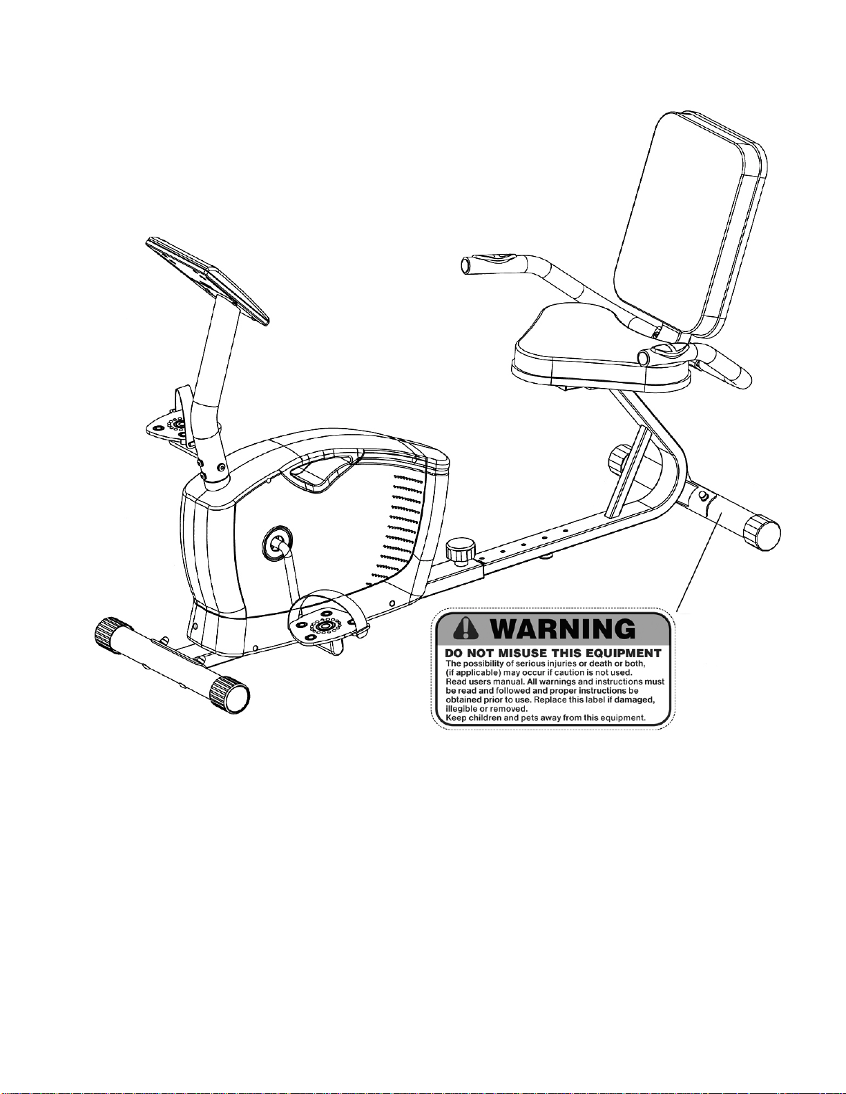
WARNING LABEL PLACEMENT
The Warning Label shown here has been placed on the Rear Stabilizer. If the label is missing or illegible,
please call customer service at 1-800-999-8899 for replacement. Apply the label in location shown.
3
Page 5
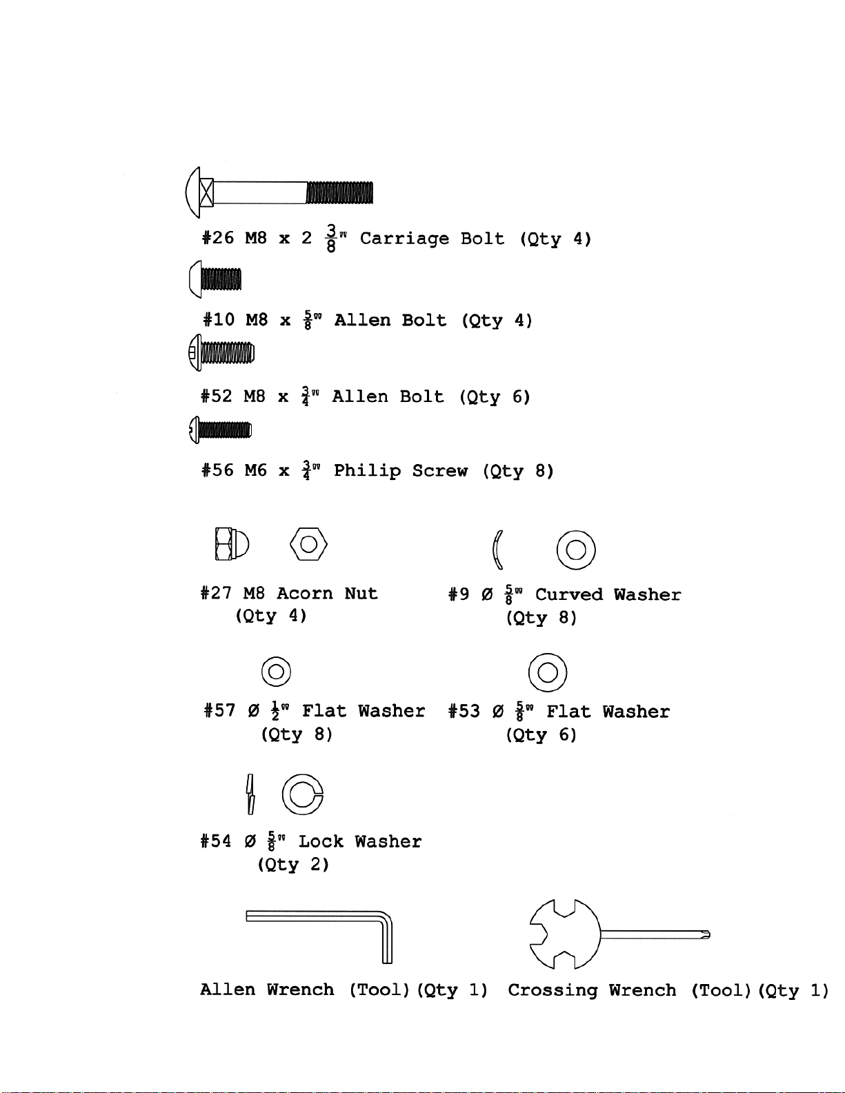
HARDWARE PACK
NOTE: The following parts are not drawn to scale. Please use your own ruler to measure the
size.
4
Page 6

ASSEMBLY INSTRUCTION
NOTE: It is strongly recommended that two or more people assemble this machine to avoid
possible injury.
STEP 1 (See Diagram1)
A.) Attach the Front Stabilizer (#25) to the Main Frame (#28). Secure it with two M8 x 2 3/8” Carriage
Bolts (#26), two ∅ 5/8” Curved Washers (#9), and two M8 Acorn Nuts (#27).
DIAGRAM 1
5
Page 7

STEP 2 (See Diagram 2)
A.) Note: Extra help may be needed when installing the computer wires in Front Post (#5).
B.) Connect the Upper Computer Wire (#6) from the bottom of Front Post to the Lower Computer Wire
(#7) from the main Fame.
C.) Connect the Upper Pulse Sensor Wire (#2) from Front Post to the Lower Pulse Sensor Wire (#8)
D.) Attach the Front Post to Main Frame. Secure them together with four M8 x 5/8” Allen Bolts (#10)
and four Ø 5/8” Curved Washers (#9).
DIAGRAM 2
6
Page 8

STEP 3 (See Diagram 3)
A.) Attach the Sliding Seat Support (#49) to Rear Stabilizer (#50).
B.) Secure them together with two M8 x 2 3/8” Carriage Bolts (#26), two Ø 5/8” Curved Washers (#9),
and two M8 Acorn Nuts (#27).
DIAGRAM 3
7
Page 9

STEP 4 (See Diagram 4)
A.) Attach the Seat (#59A) to the Seat Support Frame (#58).
B.) Secure it with three M6 x ¾” Philips Screws (#56) and four Ø ½” Flat Washers (#57).
DIAGRAM 4
8
Page 10

STEP 5 (See Diagram 5)
A.) Attach the Seat Support Frame (#58) to the Sliding Seat Support (#49).
B.) Secure it them together with four M8 x ¾” Allen Bolts (#52) and Ø 5/8” Flat Washers (#53).
DIAGRAM 5
9
Page 11

STEP 6 (see Diagram 6)
A.) Attach the Backrest Board (#59B) to the Seat Support Frame (#58). Secure it with four M6 x
¾ Philips Screws (#56) and four Ø ½” Flat Washers (#57).
B.) Attach the Handle (#61) to the Seat Support Frame. Secure it with two M8 x ¾” Allen Bolts
(#52), two Ø 5/8” Lock Washers (#54), and two Ø 5/8” Flat Washers (#53).
C.) Connect the Rear Pulse Sensor Wire (#62) on Handle to the Middle Pulse Sensor Wire
(#47) on Sliding Seat Support (#49).
DIAGRAM 6
10
Page 12

STEP 7 (See Diagram 7)
A.) Connect the Middle Pulse Sensor Wire (#47) to the Lower Pulse Sensor Wire (#8).
B.) Slide the Sliding Seat Support (#49) into the Main Frame (#28).
C.) Use the Lock Knob (#38) through the selected hole on Sliding Seat Support to lock the Seat
in the desired exercise position.
DIAGRAM 7
11
Page 13

STEP 8 (See Diagram 8)
A.) Remove four M5 x 3/8” Philips Screws (#4) from the Compute r (# 1).
B.) Connect the Upper Computer Wire (#6) to the Computer.
C.) Plug the Upper Pulse Sensor Wire (#2) into the computer.
D.) Attach the Computer to th e Front Post (#5). Secure it with the four M5 x 3/8” Philips Screws
(#4).
E.) Thread the Left Pedal (#11L) counterclockwise into the Crank (#19).
F.) Thread the Right Pedal (#11R) clockwise into the Crank.
G.) Adjust the Floor Level Adjustment (#48) to stabilize the Bike on floor.
H.) Plug the AC Adapter (#18) to110v outlet, and plug the power cord into the Main Frame
(#28). Note: Only use the original AC Adapter from manufacturer. Do not use any
Adapter which is not from manufacturer.
DIAGRAM 8
12
Page 14

Page 15

13
PARTS LIST
KEY NO. DESCRIPTION Q’ty
1 Computer 1 51 Rear Stabilizer End Cap 2
2 Upper Pulse Sensor Wir e 1 52 M8 x ¾” Allen Bolt 6
3 Ø 3/8” Cap 2 53 Ø 5/8” Flat W asher 6
4 M5 x 3/8” Philips Screw 4 54 Ø 5/8” Lock Washer 2
5 Front Post 1 55 Backrest Support End Cap 2
6 Upper Computer Wire 1 56 M6 x ¾” Philips Screw 8
7 Lower Computer Wire 1 57 Ø ½” Flat Washer 8
8 Lower Pulse Sensor Wire 1 58 Seat Support Frame 1
9 Ø 5/8” Curved W asher 8 59A Seat 1
10 M8 x 5/8” Allen Bolt 4 59B Backrest Board 1
11L Left Pedal 1 60 Ø 1” End Cap 2
11R Right Pedal 1 61 Handle 1
12 Crank Cover 2 62 Rear Pulse Sensor Wire 1
13 ST4.2 x ¾” Philips Screw 10 63 STE4.2 x ¾” Com puter Screw 2
14 ST4.2 x 1” Philips Screw 4 64 Pulse Sensor 2
15L Left Shroud 1 65 Handle Grip 2
15R Right Shroud 1 66 Ø 5/8” End Cap 1
16 Acrylic Cover 1
17 Power Cord 1
18 AC Adapter 1
19 Crank 1
20 Magnet 1
21 Belt 1
22 Ball Bearing 2
23 Ø 2 ¼” Housing Cap 2
24 Front Stabilizer Roller Cap 2
25 Front Stabilizer 1
26 M8 x 2 3/8” Carriage Bolt 4
27 M8 Acorn Nut 4
28 Main Frame 1
29 Motor 1
30 Tension Cable 1
31 M5 x ¼” Philips Screw 2
32 M5 x 5/8” Philips Screw 2
33 Ø 7/8” Bushing 1
34 Ø 7/8” Washer 1
35 Hex Nut 1
36 Magnetic Sensor 1
37 Magnetic Sensor Wire 1
38 Lock Knob 1
39 M10 Flange Nut 2
40 M6 Bolt 2
41 Magnetic Wheel 1
42 U-shaped Bracket 2
43 Ø ½” Lock Washer 2
44 M6 Hex Nut 2
45 Sleeve 1
46 Sliding Sleeve 1
47 Middle Pulse Sensor Wire 1
48 Floor Level Adjustment 1
49 Sliding Seat Support 1
50 Rear Stabilizer 1
14
Page 16

IMPEX® INC.
LIMITED WARRANTY
IMPEX Inc. ("IMPEX®") warrants this product to be free f rom defects in work manship and m aterial, under normal us e
and service conditions, for a period of two years on the Frame fr om the date of purchase. This warranty extends only
to the original purchaser. IMPEX's obligation under this Warranty is limited to replacing or repairing, at IMPEX's option.
All returns must be pre- authorized by IMPEX. Pre-authorization may be obtained by calling IMPEX Customer Ser vice
Department at 1-800-999-8899. All freights for products return to IMPEX must be prepaid by the customer. This
warranty does not extend to any product or damage to a product caused by or attributable to freight damage, abuse,
misuse, improper or abnorm al usage or repairs not provided by an IMPEX authorized service center or for products
used for commer cial or rental purposes. No other warranty beyond that specifically set forth above is authorized by
IMPEX.
IMPEX is not responsible or liable for indir ect, s pec ial or cons equential damages arising out of or in c onnec tion with the
use or performance of the product or other damages with respect to any economic loss, loss of property, loss of
revenues or profits, loss of enjoyments or use, costs of removal, installation or other consequential damages or
whatsoever natures. Some states do not allow the exclusion or limitation of incidental or consequential damages.
Accordingly, the above limitation may not apply to you.
The warranty extended hereunder is in lieu of any and all other warranties and any implied warranties of m e rc hantability
or fitness for a particular purpose is limited in its scope and duration to the terms s et forth herein. Som e states do not
allow limitations on how long an implied warranty lasts. Accordingly, the above limitation may not apply to you.
This warranty gives you specific legal right. You may also have other rights which vary from state to state.
on-l ine www.impex-fitness.com
ORDERING REPLACEMENT PARTS
Replacement parts can be ordered by calling our Customer Service Department toll- free at 1-800-999-8899 dur ing our
regular business hours: Monday through Friday, 9 am until 5 pm Pacific standard time.
IMPEX
14777 Don Julian
City of Industry, CA 91746
®
INC.
info@impex-fitness.com
When ordering replacement part, always give the following information.
1. Model
2. Description of Parts
3. Part Number
4. Date of Purchase
15
Register
 Loading...